EP2500496A2 - Agencement de porte - Google Patents
Agencement de porte Download PDFInfo
- Publication number
- EP2500496A2 EP2500496A2 EP12001741A EP12001741A EP2500496A2 EP 2500496 A2 EP2500496 A2 EP 2500496A2 EP 12001741 A EP12001741 A EP 12001741A EP 12001741 A EP12001741 A EP 12001741A EP 2500496 A2 EP2500496 A2 EP 2500496A2
- Authority
- EP
- European Patent Office
- Prior art keywords
- plate
- profile
- door
- parallelogram
- guide
- Prior art date
- Legal status (The legal status is an assumption and is not a legal conclusion. Google has not performed a legal analysis and makes no representation as to the accuracy of the status listed.)
- Granted
Links
Images

Classifications
-
- E—FIXED CONSTRUCTIONS
- E05—LOCKS; KEYS; WINDOW OR DOOR FITTINGS; SAFES
- E05D—HINGES OR SUSPENSION DEVICES FOR DOORS, WINDOWS OR WINGS
- E05D15/00—Suspension arrangements for wings
- E05D15/06—Suspension arrangements for wings for wings sliding horizontally more or less in their own plane
- E05D15/10—Suspension arrangements for wings for wings sliding horizontally more or less in their own plane movable out of one plane into a second parallel plane
- E05D15/1021—Suspension arrangements for wings for wings sliding horizontally more or less in their own plane movable out of one plane into a second parallel plane involving movement in a third direction, e.g. vertically
-
- E—FIXED CONSTRUCTIONS
- E05—LOCKS; KEYS; WINDOW OR DOOR FITTINGS; SAFES
- E05D—HINGES OR SUSPENSION DEVICES FOR DOORS, WINDOWS OR WINGS
- E05D15/00—Suspension arrangements for wings
- E05D15/06—Suspension arrangements for wings for wings sliding horizontally more or less in their own plane
- E05D15/10—Suspension arrangements for wings for wings sliding horizontally more or less in their own plane movable out of one plane into a second parallel plane
- E05D2015/1028—Suspension arrangements for wings for wings sliding horizontally more or less in their own plane movable out of one plane into a second parallel plane with only the wing moving transversely
- E05D2015/1031—Suspension arrangements for wings for wings sliding horizontally more or less in their own plane movable out of one plane into a second parallel plane with only the wing moving transversely the wing supported on arms extending from the carriage
- E05D2015/1036—Suspension arrangements for wings for wings sliding horizontally more or less in their own plane movable out of one plane into a second parallel plane with only the wing moving transversely the wing supported on arms extending from the carriage the arms being movable in vertical, e.g. transverse, planes
-
- E—FIXED CONSTRUCTIONS
- E05—LOCKS; KEYS; WINDOW OR DOOR FITTINGS; SAFES
- E05Y—INDEXING SCHEME ASSOCIATED WITH SUBCLASSES E05D AND E05F, RELATING TO CONSTRUCTION ELEMENTS, ELECTRIC CONTROL, POWER SUPPLY, POWER SIGNAL OR TRANSMISSION, USER INTERFACES, MOUNTING OR COUPLING, DETAILS, ACCESSORIES, AUXILIARY OPERATIONS NOT OTHERWISE PROVIDED FOR, APPLICATION THEREOF
- E05Y2201/00—Constructional elements; Accessories therefor
- E05Y2201/60—Suspension or transmission members; Accessories therefor
- E05Y2201/622—Suspension or transmission members elements
- E05Y2201/638—Cams; Ramps
-
- E—FIXED CONSTRUCTIONS
- E05—LOCKS; KEYS; WINDOW OR DOOR FITTINGS; SAFES
- E05Y—INDEXING SCHEME ASSOCIATED WITH SUBCLASSES E05D AND E05F, RELATING TO CONSTRUCTION ELEMENTS, ELECTRIC CONTROL, POWER SUPPLY, POWER SIGNAL OR TRANSMISSION, USER INTERFACES, MOUNTING OR COUPLING, DETAILS, ACCESSORIES, AUXILIARY OPERATIONS NOT OTHERWISE PROVIDED FOR, APPLICATION THEREOF
- E05Y2201/00—Constructional elements; Accessories therefor
- E05Y2201/60—Suspension or transmission members; Accessories therefor
- E05Y2201/622—Suspension or transmission members elements
- E05Y2201/684—Rails; Tracks
-
- E—FIXED CONSTRUCTIONS
- E05—LOCKS; KEYS; WINDOW OR DOOR FITTINGS; SAFES
- E05Y—INDEXING SCHEME ASSOCIATED WITH SUBCLASSES E05D AND E05F, RELATING TO CONSTRUCTION ELEMENTS, ELECTRIC CONTROL, POWER SUPPLY, POWER SIGNAL OR TRANSMISSION, USER INTERFACES, MOUNTING OR COUPLING, DETAILS, ACCESSORIES, AUXILIARY OPERATIONS NOT OTHERWISE PROVIDED FOR, APPLICATION THEREOF
- E05Y2800/00—Details, accessories and auxiliary operations not otherwise provided for
- E05Y2800/67—Materials; Strength alteration thereof
- E05Y2800/672—Glass
-
- E—FIXED CONSTRUCTIONS
- E05—LOCKS; KEYS; WINDOW OR DOOR FITTINGS; SAFES
- E05Y—INDEXING SCHEME ASSOCIATED WITH SUBCLASSES E05D AND E05F, RELATING TO CONSTRUCTION ELEMENTS, ELECTRIC CONTROL, POWER SUPPLY, POWER SIGNAL OR TRANSMISSION, USER INTERFACES, MOUNTING OR COUPLING, DETAILS, ACCESSORIES, AUXILIARY OPERATIONS NOT OTHERWISE PROVIDED FOR, APPLICATION THEREOF
- E05Y2900/00—Application of doors, windows, wings or fittings thereof
- E05Y2900/10—Application of doors, windows, wings or fittings thereof for buildings or parts thereof
- E05Y2900/13—Type of wing
- E05Y2900/132—Doors
Definitions
- the present invention relates to a door arrangement, in particular a glass door arrangement, according to the preamble of claim 1.
- Door arrangements are known in the art.
- sliding sliding door arrangements are known in the prior art, which find particular use when a swing door is difficult to realize due to spatial limitations.
- a movable element is often moved parallel to a stationary element.
- element or door element is to be understood in the broad sense and include both plates, glass plates, plastic plates, doors, glass doors and the like.
- plane should also be understood to mean curved and curved planes.
- the known conventional sliding door assemblies have the disadvantage that an offset between a movable element of such a sliding door assembly and the stationary element is technically conditioned, because the movable element has to be guided parallel offset to the fixed element for opening or closing. For this purpose, the movable element must be spaced from the ground. In addition to restricting the design possibilities of said known sliding door arrangements, these also have the disadvantage that they are cumbersome to clean.
- a generic sliding door arrangement that allows a second, movable plate in the closed state in a plane with a fixed first plate of the sliding door assembly is arranged, is from the DE 103 19 170 A1 known.
- a device is disclosed, which allows a parallelogram displacement of the second plate relative to the first plate, so that a surface side of the second plate in the closed state in a plane flush with a surface side of the first plate.
- the generic door assembly has the disadvantage that opening and closing high forces conditionally and that a conclusion of the second plate with the ground in the closed state is not possible because a distance from the ground is needed to move the second plate.
- Another generic door assembly is on the DE 19725355 C2 known, which describes a sliding door device, which can be both lowered at the end of the sliding operation, as well as in the direction of a cream under closing can be moved.
- the closed position is effected by the fact that the end of a support and guide rail system is bent to one side down, on the other hand, the bent part is bent in the direction of the frame.
- These rails which are bent downwards and to the side, move the rollers to which the door leaf hangs downwards and inwards, thereby causing a plane-parallel closing operation.
- a disadvantage of this arrangement is the cumbersome operability of the door system, since the entire weight of the door must be lifted to open from the closed position to transfer the partially lowered rollers from the slope to the horizontal of the railroad.
- the invention is therefore based on the object to further develop the generic door assembly such that it can be operated with little effort and smoothly.
- the curve is formed at least in regions in the form of a helix, wherein the helix forms a constant slope, and preferably the curve has an L-shape and / or a U-shape, and in particular the curve in the region of the extensions a groove is arranged.
- the door arrangement comprises an upper and / or a lower guide for the first and / or the second plate, wherein the second plate comprises at least a first parallelogram, and the first parallelogram with the first plate, in particular by means of rollers, connectable is and preferably the first parallel guide for guiding the second plate comprises a bolt and / or sliding block.
- the first plate and / or the wall element at least partially has or have at least one profile and the profile comprises at least one groove, wherein preferably the at least one groove has at least one extension.
- the first parallelogram guide comprises a spring which receives by means of a positioning device, in particular in the form of a linear guide, forces acting on the second plate from a distal leg and transmits it to a profile near leg of the first parallelogram.
- the spring is arranged within the first parallelogram so that the spring holds the second plate in an open or a closed state by the spring exerts forces on the first parallelogram to this either in its folded or unfolded state to fix.
- this is almost parallel along the first plate and / or the wall element displaceable, wherein the second plate is spaced from the first plate and / or the wall element, in particular by 3 to 4 millimeters.
- the lower guide comprises a bottom element, comprising a second parallelogram corresponding to the first parallelogram, so that the second bottom element is guided both at its upper end and at its lower end at least during opening or closing.
- the bottom element comprises a carriage, wherein preferably at least one magnet is arranged on the carriage, in particular on one of the sides of the carriage, so that the carriage in the open and in the closed state is detachably connectable to one of the side walls of the bottom element ,
- first plate and / or the second plate in the form of a door, a glass door, an acrylic glass door, a plastic door, preferably made of transparent plastic, a wooden door or the like is formed and / or at least partially comprising a glass, plastic, or acrylic glass pane, and preferably the first plate and / or the second plate comprises at least one seal on one of its surfaces and in particular the first plate and / or the second plate has a diameter of 8 mm.
- the invention is therefore based on the surprising finding that a door assembly with a first fixed plate or a wall and a movable relative to the first plate second plate allows a particularly simple cleaning of the door assembly when moving the second plate, preferably a plate with a diameter of 8 mm, in particular a glass plate, is provided in the same plane as the first plate or the wall.
- provision is made in particular for the second plate to move both parallel and vertically and downwards to the first plate during the opening and closing in order to enable a spatial separation of a desired region to be separated. If the door assembly is thus transferred from an open to a closed state, the second plate is moved by means of a parallelogram in both the plane of the first plate or the wall and relative to the first plate or the wall down.
- close closure of the second panel with a floor member results, as long as the door assembly is closed, while the second panel is easily moved in the open state by a distance from the floor.
- an upper and optionally a lower guide for the second plate is provided according to the invention.
- an upper guide comprises one or more load-bearing rollers, which are in operative connection with at least one parallelogram guide.
- the parallelogram guides are connected by means of at least one roller in operative connection with the first plate or the wall and at the same time with the second plate.
- rollers to which the other parts of the door assembly are fixed always move on a horizontal profile that does not, as in the arrangement according to. DE 19725355 C2 is proposed, is bent at the ends.
- the rollers according to the inventive arrangement need not be lifted out of a lowered end position and can therefore be operated largely without much effort along the horizontal.
- the first plate or the wall at least partially comprise a profile along which the second plate is movable by means of the at least one roller. It is particularly provided that the profile has a gate for at least one sliding block or at least one bolt, so that the second plate can be performed at least partially plane-parallel to the profile. Furthermore, the profile P preferably has one or more grooves, which restrict the movement of the sliding blocks and / or the bolts. It is advantageous if, for example, a first groove is arranged at a first distance from the upper end of the profile and a second groove and further grooves are arranged at a second or at other intervals, in order to allow different parallelogram guides at one end the respective grooves in different foothills with possibly different functional purposes.
- a guide comes through extensions of the groove in the form of a helix.
- the helix is a continuously curved curve, which is designed in particular such that a movement takes place along the curve in a first direction, in a second and in a third direction, wherein the first, second and third directions are each perpendicular are arranged to each other.
- an extension of the groove may be in the form of an L, so that the second plate moves parallel to the first plate or wall at the transition from opening to closing and simultaneously into both the plane of the first flap and the wall and moved down.
- the first plate and the wall and the second plate form a plane and by the quadrant of the curve lowering the second plate as desired is reached.
- It may of course also be provided to provide a semicircle as a curve shape of an extension of a groove. This is particularly advantageous when the plates are plates made of easily damaged materials such as glass.
- the semicircular shape of the tail causes the second plate moves parallel only in the direction of the desired end position along the first plate or the wall and is then brought plane-parallel with a safety distance in the plane of the first plate or wall and subsequently in the another lowering is again brought closer to the first plate or wall horizontally, so that they optionally complete even form-fitting with each other.
- Wegbeskyndes element can be integrated into the profile, for example, to provide a stop a direction of movement of the second plate.
- Wegbeskyndes element can be formed for example by a special shape of the profile, such as an increase.
- a parallelogram guide has a profile-proximate and a profile-distant leg, which are connected via a hinge arrangement.
- the at least one bolt or the at least one sliding block is fastened to one of the legs remote from the profile.
- the sliding block performs a circular, in particular a quarter-circle, movement, preferably with a radius of 15 mm, when the parallelogram guide is folded together by spatially fixing one or more profiled limbs from the open state.
- the radius of said movement is adapted to the course of at least one of the grooves, that the at least one bolt and / or the at least one sliding block is arranged in a closed state of the second plate in the profile that the parallelogram due to the from the tail of the Groove given movement in the folded state, the second plate flush (palparallel) with the first plate and / or the wall closes.
- the parallelogram guide comprises at least one spring which at least partially carries the weight of the second plate, in particular in which the at least one spring receives forces on one of the profile-remote legs and transmits them to the profile-near leg. It has proved to be particularly advantageous if, by means of a positioning device, such as by means of a linear guide, the at least one spring is arranged such that it holds the second plate in the open or closed state in which unfolds the parallelogram unfolded or folded is.
- the lower guide of the second plate has a parallelogram guide, which guides the second plate when closing in the plane of the first plate or the wall and at the same time parallel and downward, so that in the same movement as that, which is due to the upper guide results.
- the lower guide at least one carriage, which is designed such that the second plate can be received in a U-profile.
- the U-profile is movably mounted and can by means of a parallelogram a movement corresponding to the movement of the second plate, as it is caused by the upper guide run.
- This is achieved in that the carriage is connected to the lower guide by means of a further hinge arrangement, which is similar to the above-described hinge arrangement.
- the U-profile has at least one recess for a magnet or the like, preferably two recesses on each side of the U-profile, so that the carriage is securely fixed in its open position in the open and closed state is and can not tilt. This ensures that the second plate can be inserted into the carriage or in the U-profile.
- One or more carriages preferably in each case in the region of the door end, can be provided in order to keep the door in the plane-parallel state. Possibly.
- the carriage can also extend over the entire width of the door.
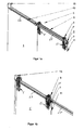
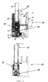
- FIG. 1 a is a door assembly 1 according to the invention shown in the closed state.
- the door assembly comprises a profile 2 and rollers 3, 3 ', on which a parallelogram 5 is arranged.
- a second plate in the form of a door element 11 is arranged, which is located in a plane with a first plate or wall in the form of a door element 13.
- the door element 11 can be moved by means of the rollers 3 and the parallelogram 5 along the profile 2, wherein this movement is limited by a limiting element 15.
- FIG. 1b a door assembly 1 is shown in the open state.
- the door element 11 is compared to FIG. 1 a is shifted to the left and is parallel to the door element 13.
- FIG. 1b The door element 11 thus covers the door element 13 FIG. 1 a.
- one or more parallelogram guides 5, 5 'are mounted on the profile 2, in each case via one or more load-bearing rollers 3. If two or more parallelogram guides 5, 5 'are used, they can be connected to a connecting element 9.
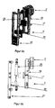
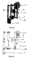
- Such a parallelogram guide 5,5 'according to the invention is in the Figures 2a to 3b shown in open and closed state.
- FIG. 2a shows a perspective exploded view of a parallelogram 5 'comprising a sliding block 17 and two legs 19, 21 and a linear guide 23 and a spring 25 in the closed state.
- FIG. 2b shows the parallelogram 5 'as a side exploded view, the FIGS. 3a and 3b the parallelogram guide 5 'in the open state.
- profile 2 represents a backdrop for one or more bolts and / or sliding blocks 17, which on a parallelogram 5, 5 'according to, for example, the Figures 2a to 3b or not shown fasteners are attached.
- the freedom of movement of the sliding blocks 17 is limited by one or more grooves 27,27 'in the profile 2.
- door element 11 can be attached to the profile remote leg 21.
- stiffness-enhancing cross links may reinforce the parallelogram guide 5 '.
- the sliding blocks 17 can be arranged at different heights in order to allow the use of different grooves 27, 27' in the profile 2. This is particularly advantageous if, for example, two parallelogram 5, 5 'at each one end of a door member 11 is to be arranged, so that the door is mounted right and left, and the sliding blocks 17 are guided in two different grooves 27,27 ', which are arranged one above the other.
- the optional different height of the attachment of the sliding block 17 also has the advantage that different extensions of the grooves can be designed.
- the sliding block 17 is attached to the profile remote legs 21, so that the sliding block 17 performs in a collapsing the parallelogram 5, 5' under spatial fixation of the profile near leg 19 a preferably quarter-circular motion.
- the radius of this movement is in particular so on the course of the groove 27 of the profile 2 from the FIGS. 1a and 1b adapted that the sliding block 17 in a parking position in the closed state of the door assembly 1 from FIG. 1a is so deep in the profile 2 that the parallelogram 5, 5 'is folded together by the forced during the folding movement such that the second plate or the door member 11 is flush with the door member 13.
- the spring 25 receives forces on the leg 21 remote from the profile and transmits it to the profile-near leg 19.
- the spring 25 by means of a positioning device, such as a linear guide 23, via which the spring 25 is fixed to the profiled leg 21, are arranged so that the spring 11, the door element is fixed open and closed in the two end position.
- FIGS. 4a and 4b An example of a groove 27 according to the invention is in the FIGS. 4a and 4b shown, wherein a groove 27 is shown with an extension 29 and 31 on a section of a profile 2.
- the groove 27 behaves similar to a backdrop, but in reverse function.
- the groove 27,29 and 31 leads the sliding block 17 from the Figures 2a to 3b in the profile 2 and thus coordinates, on the one hand, the position of the parallelogram guide 5, 5 'in the direction of the profile 2 as well as the folding state of the parallelogram guide 5, 5'.
- a groove 27 is shown with a first Nutverlauf 29, which preferably has a radius of 15mm. These are the first one Nutverlauf 29 around a continuously curved curve which is formed such that a movement of the sliding block 17 along the curve in a first direction substantially parallel to the profile 2 and in a second and in a third direction, wherein the first, second and third third direction are each arranged at right angles to each other.
- FIG. 4b An alternative embodiment is in FIG. 4b shown.
- a second Nutverlauf 31 is shown, which describes an L.
- many different groove shapes 29, 31 are provided, which are all suitable for enabling a translation of the sliding block 11 according to the invention.
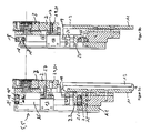
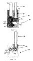
- FIGS. 3a to 4b While in the FIGS. 3a to 4b each exploded views of the parallelogram 5.5 'are shown in the open or closed state, shows FIGS. 5a and 5b now the assembled parallelogram 5.5 'partially cut from the side.
- the profile near leg 19 and the distal leg 21 are each hinged together via an upper connecting plate 18 as the first hinge assembly and a lower connecting plate 20 as a second hinge assembly, wherein on the side of the profile near leg 19, the connecting plates 18 and 20 at the pivot points 18 'and 20 'and are rotatably articulated on the side of the profile remote leg 21 at the pivot points and pivot points 18 "and 20".
- the respective pivot points 18 "and 18" and 20 'and 20 “have a distance A from one another by which the two legs 19 and 21 can be displaced linearly in the manner of a parallelogram Figures 2 .
- off-center pivot 18 "and 20" can be rotated by folding the connecting plates 18 and 20 by an angle of 90 degrees so that the two legs 19 and 21 move against each other and lie in the final phase together, as in particular FIG. 5b is apparent.
- FIG. 5a the second plate 11 in its mounted state on the leg 21 spaced from the first plate 13, ie in the open state.
- the two plates 11 and 13 are plane-parallel ( 5 b ) to each other.
- FIG. 5a It is also out FIG. 5a It can be seen that the pivoting distance of the two plates 11 and 13 to each other the distance A, as in FIG. 5b shown above, ie, the plate 11 is pivoted not only by the distance A down, but also in the direction of the first plate 13, that is, a quarter circle arc each with the pivot point 18 'and 20'.
- the sliding block 17 is within the profile 2 in the groove 27 ( FIG. 5a ) and the groove 29, 31 (FIG. FIG. 5b ) guided.
- the spacing in the final phase of the groove 29, 31 with respect to the linear groove 27 again corresponds to the distance A, by which the two legs 19 and 21 are pivoted against each other.
- the sliding block 17 itself is attached via a mounting unit 16 on the profile remote leg 21 and passes through the parallelogram 5.5 '.
- the spring 25 is hinged on the one hand to the upper connecting plate 18 in the point 18 ", while it is mounted at the opposite lower end in a spring mounting unit 24.
- This spring mounting unit 24 is on attached near the profile leg 21, wherein the spring 25 is adjusted in its spring action, that the two legs 19 and 21 in the open starting position according to FIG. 5a being held.
- the spring force is designed so that it compensates the weight of the plate 11 so that the sliding block 17 remains largely frictionless in its movement in the groove 27, 29 and 31 and thereby can be easily moved.
- the plate 11 itself is moved by sliding under the action of the sliding block 17 as it enters the curved Nutverlauf 29, 31 by folding the parallelogram 5.5 'from the open position ( 5a ) in the closed position ( 5 b ) shifted and thereby lowered on the one hand vertically by the distance A and on the other by the same amount A horizontally displaced against the other plate 13.
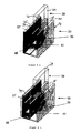
- a first floor member 33 is shown that includes a second parallelogram guide 35 and a carriage 37.
- a door element 39 can be arranged inside the carriage 37.
- the carriage 37 is located, as in the Figures 6a and 6b and 8b, when closed.
- the FIGS. 7a and 7b and 8a show the carriage 37 in the open state.
- the operation of the bottom element 33 is in particular the perspective views of FIGS. 8a and 8b clear.
- FIG. 8a the bottom element 33 in the open state and the FIG. 8b in the closed state.
- the first door member 39 is disposed within the carriage 37 when it is inserted into it.
- the carriage 37 subsequently performs the same movement as the upper guide with the parallelogram guide 5, 5 '.
- the carriage 37 is rotatably mounted about an axis 43 in order to allow the translational movement from the open to the closed state.
- a magnet 41 is advantageously provided, which is arranged both on the right and on the left of the carriage 37 to fix the carriage 37 on the walls of the bottom member 33 to releasably.
- the bottom element 33 consists of a double rail 34 which has two side walls 36 and 36 'and receives between them a central web 38.
- a first guide channel 40 is formed, while between the second side wall 36 'and the middle path 38, a second guide channel 42 is arranged.
- the first door element 39 which corresponds to the door element 11 Figure 1-5 corresponds, slidably disposed, while in the second guide channel 42, the second door member 44 is fixedly disposed and thus corresponds to the door member 13.
- the carriage 27 is U-shaped and thus also has a guide channel 45 which is aligned with the first guide channel 40 in the open position, so that that the first door member 39 can be moved without hindrance in both channels 40 and 45 before the deflection process ,
- FIG. 8a This situation is in FIG. 8a illustrated, in which the carriage 37 is in the raised position, wherein the two door members 39 and 44 are arranged parallel to each other.
- FIG. 8b in the closed position according to FIG. 8b the two door elements 39 and 44 arranged plane-parallel one behind the other, wherein the carriage 37 in the lowered, in FIG. 8b is moved to the lower left position.
- the carriage 37 itself is arranged in the embodiment shown at the end of the bottom member 33 and, as shown FIG. 6 and 7 can be seen, with a movable connecting plate 46, which largely corresponds to the connecting plate 18 and 20 as a hinge, via a mounting unit 47 with the side wall 36 'rotatable about the axis 43, which is in the fixedly connected to the side wall 36' mounting unit 47, and hinged directly about the axis 48, so that the carriage 37 can be pivoted about both axes 43 and 48 (center distance corresponds to the above-defined distance A) each about a quarter circle around down.
- the fixing of the carriage 37 takes place in the closed state via a magnet arrangement 41, the parts of which are arranged in the side wall 36 'and in the carriage 37 and act together in the closed state.
- a similar magnet arrangement 41 'in the closed state on the opposite arranged on the other side of the carriage 37 and in the first side wall 36 for fixing in the open state.
- a retaining spring 49 is shown, whose eye about the axis 43 and whose legs are respectively disposed on the inside of the side wall 36 'and the carriage 37.
- This retaining spring 49 holds the carriage 37 in the unloaded state in the open position, so that it is continuously aligned with the first guide channel 40. Only by the action of the weight of the door member 39 in the downward movement of the carriage 37 is then moved against the spring force down and then horizontally in the closed position, in which case the magnet assembly 41 laterally fixed the carriage in the closed state.
Landscapes
- Engineering & Computer Science (AREA)
- Mechanical Engineering (AREA)
- Support Devices For Sliding Doors (AREA)
- Securing Of Glass Panes Or The Like (AREA)
- Wing Frames And Configurations (AREA)
- Specific Sealing Or Ventilating Devices For Doors And Windows (AREA)
Applications Claiming Priority (1)
| Application Number | Priority Date | Filing Date | Title |
|---|---|---|---|
| DE201110013935 DE102011013935B4 (de) | 2011-03-14 | 2011-03-14 | Türanordnung |
Publications (3)
| Publication Number | Publication Date |
|---|---|
| EP2500496A2 true EP2500496A2 (fr) | 2012-09-19 |
| EP2500496A3 EP2500496A3 (fr) | 2015-03-18 |
| EP2500496B1 EP2500496B1 (fr) | 2016-07-27 |
Family
ID=45887888
Family Applications (1)
| Application Number | Title | Priority Date | Filing Date |
|---|---|---|---|
| EP12001741.3A Active EP2500496B1 (fr) | 2011-03-14 | 2012-03-14 | Agencement de porte |
Country Status (2)
| Country | Link |
|---|---|
| EP (1) | EP2500496B1 (fr) |
| DE (1) | DE102011013935B4 (fr) |
Families Citing this family (1)
| Publication number | Priority date | Publication date | Assignee | Title |
|---|---|---|---|---|
| DE102024004297A1 (de) | 2024-12-17 | 2026-06-18 | Breuer-Löwenstein Know-How GbR (vertretungsberechtigter Gesellschafter: Thomas Breuer-Löwenstein, 56567 Neuwied) | Türanordnung, insbesondere Glastüranordnung |
Citations (2)
| Publication number | Priority date | Publication date | Assignee | Title |
|---|---|---|---|---|
| DE19725355C2 (de) | 1997-06-16 | 1999-04-15 | Ems Isoliertueren Mickeleit Gm | Schiebetürschließeinrichtung |
| DE10319170A1 (de) | 2003-04-29 | 2004-11-25 | Zoltan Anton Kiefer | Raumteiler |
Family Cites Families (2)
| Publication number | Priority date | Publication date | Assignee | Title |
|---|---|---|---|---|
| JPH07224570A (ja) * | 1994-02-15 | 1995-08-22 | Masaaki Kamezaki | 大形冷凍庫等用スライディング式ドア装置 |
| DE202004003010U1 (de) * | 2004-02-27 | 2005-07-14 | Coolit Isoliersysteme Gmbh | Schiebetür für Gefrier-, Kühl- oder Betriebsräume |
-
2011
- 2011-03-14 DE DE201110013935 patent/DE102011013935B4/de not_active Expired - Fee Related
-
2012
- 2012-03-14 EP EP12001741.3A patent/EP2500496B1/fr active Active
Patent Citations (2)
| Publication number | Priority date | Publication date | Assignee | Title |
|---|---|---|---|---|
| DE19725355C2 (de) | 1997-06-16 | 1999-04-15 | Ems Isoliertueren Mickeleit Gm | Schiebetürschließeinrichtung |
| DE10319170A1 (de) | 2003-04-29 | 2004-11-25 | Zoltan Anton Kiefer | Raumteiler |
Also Published As
| Publication number | Publication date |
|---|---|
| EP2500496A3 (fr) | 2015-03-18 |
| DE102011013935A1 (de) | 2012-09-20 |
| DE102011013935B4 (de) | 2013-03-21 |
| EP2500496B1 (fr) | 2016-07-27 |
Similar Documents
| Publication | Publication Date | Title |
|---|---|---|
| EP1959080B1 (fr) | Butée de battant mobile de fenêtre ou de porte | |
| DE19846308C2 (de) | Abdicht- und Verriegelungsvorrichtung für Fenster oder Türen | |
| EP1314626A1 (fr) | Porte coulissante et pivotante pour véhicules, notamment porte des passagers pour véhicules de transport urbain de personnes | |
| AT519903B1 (de) | Schiene zur Führung eines Schlittens einer Möbeltüre | |
| DE2706013A1 (de) | Treibstangenbeschlag fuer aus metall- oder kunststoffprofilen zusammengesetzte fenster, tueren o.dgl. | |
| EP3798390A1 (fr) | Installation de pliage | |
| DE68907768T2 (de) | Faltwand, bestehend aus miteinander gelenkig verbundenen doppelwandigen Flügeln. | |
| DE10319170A1 (de) | Raumteiler | |
| EP2799651A1 (fr) | Ferrure de porte coulissante pour meuble | |
| DE2261946A1 (de) | Beschlag fuer aus metall- oder kunststoffprofilen gefertigte fenster und tueren od.dgl | |
| DE2352869C3 (de) | Hebe-Schwenk-Tür | |
| DE2517367A1 (de) | Beschlag fuer kipp-schwenkfluegel von fenstern, tueren o. dgl. | |
| EP2500496B1 (fr) | Agencement de porte | |
| DE102020111221A1 (de) | Laufwagenanordnung für eine Schiebetür | |
| AT15365U1 (de) | Verglasungssystem | |
| EP1298271A2 (fr) | Chariot pour une ferrure pour portes ou fenêtres à soulèvement et coulissement et ferrure avec un tel chariot | |
| EP1488977A1 (fr) | Porte louvoyante coulissante pour véhicule. | |
| EP2527575B1 (fr) | Ferrure de porte coulissante | |
| DE8201403U1 (de) | Eckumlenkung für Treibstangenbeschläge von Fenstern, Türen od. dgl. | |
| DE8123266U1 (de) | Eckumlenkung fuer treibstangenbeschlaege von fenstern, tueren o.dgl. | |
| CH622854A5 (en) | Setting-out device on wings or the like of windows or doors | |
| DE19825071A1 (de) | Parallelausstellfenster mit Drehfunktion | |
| DE202006015290U1 (de) | Beschlag für ein Fenster oder eine Tür | |
| EP2267257A1 (fr) | Dispositif de blocage | |
| DE7246258U (de) | Beschlag fuer aus metall- oder kunststoffprofilen gefertigte fenster und tueren od.dgl. |
Legal Events
| Date | Code | Title | Description |
|---|---|---|---|
| PUAI | Public reference made under article 153(3) epc to a published international application that has entered the european phase |
Free format text: ORIGINAL CODE: 0009012 |
|
| AK | Designated contracting states |
Kind code of ref document: A2 Designated state(s): AL AT BE BG CH CY CZ DE DK EE ES FI FR GB GR HR HU IE IS IT LI LT LU LV MC MK MT NL NO PL PT RO RS SE SI SK SM TR |
|
| AX | Request for extension of the european patent |
Extension state: BA ME |
|
| PUAL | Search report despatched |
Free format text: ORIGINAL CODE: 0009013 |
|
| AK | Designated contracting states |
Kind code of ref document: A3 Designated state(s): AL AT BE BG CH CY CZ DE DK EE ES FI FR GB GR HR HU IE IS IT LI LT LU LV MC MK MT NL NO PL PT RO RS SE SI SK SM TR |
|
| AX | Request for extension of the european patent |
Extension state: BA ME |
|
| RIC1 | Information provided on ipc code assigned before grant |
Ipc: E05D 15/10 20060101AFI20150210BHEP |
|
| 17P | Request for examination filed |
Effective date: 20150918 |
|
| RBV | Designated contracting states (corrected) |
Designated state(s): AL AT BE BG CH CY CZ DE DK EE ES FI FR GB GR HR HU IE IS IT LI LT LU LV MC MK MT NL NO PL PT RO RS SE SI SK SM TR |
|
| GRAP | Despatch of communication of intention to grant a patent |
Free format text: ORIGINAL CODE: EPIDOSNIGR1 |
|
| INTG | Intention to grant announced |
Effective date: 20160215 |
|
| RAP1 | Party data changed (applicant data changed or rights of an application transferred) |
Owner name: TARDIS GMBH & CO. KG |
|
| GRAS | Grant fee paid |
Free format text: ORIGINAL CODE: EPIDOSNIGR3 |
|
| GRAA | (expected) grant |
Free format text: ORIGINAL CODE: 0009210 |
|
| AK | Designated contracting states |
Kind code of ref document: B1 Designated state(s): AL AT BE BG CH CY CZ DE DK EE ES FI FR GB GR HR HU IE IS IT LI LT LU LV MC MK MT NL NO PL PT RO RS SE SI SK SM TR |
|
| REG | Reference to a national code |
Ref country code: GB Ref legal event code: FG4D Free format text: NOT ENGLISH |
|
| REG | Reference to a national code |
Ref country code: CH Ref legal event code: EP |
|
| REG | Reference to a national code |
Ref country code: AT Ref legal event code: REF Ref document number: 815944 Country of ref document: AT Kind code of ref document: T Effective date: 20160815 |
|
| REG | Reference to a national code |
Ref country code: IE Ref legal event code: FG4D Free format text: LANGUAGE OF EP DOCUMENT: GERMAN |
|
| REG | Reference to a national code |
Ref country code: DE Ref legal event code: R096 Ref document number: 502012007743 Country of ref document: DE |
|
| REG | Reference to a national code |
Ref country code: LT Ref legal event code: MG4D |
|
| REG | Reference to a national code |
Ref country code: NL Ref legal event code: MP Effective date: 20160727 |
|
| PG25 | Lapsed in a contracting state [announced via postgrant information from national office to epo] |
Ref country code: IT Free format text: LAPSE BECAUSE OF FAILURE TO SUBMIT A TRANSLATION OF THE DESCRIPTION OR TO PAY THE FEE WITHIN THE PRESCRIBED TIME-LIMIT Effective date: 20160727 Ref country code: FI Free format text: LAPSE BECAUSE OF FAILURE TO SUBMIT A TRANSLATION OF THE DESCRIPTION OR TO PAY THE FEE WITHIN THE PRESCRIBED TIME-LIMIT Effective date: 20160727 Ref country code: RS Free format text: LAPSE BECAUSE OF FAILURE TO SUBMIT A TRANSLATION OF THE DESCRIPTION OR TO PAY THE FEE WITHIN THE PRESCRIBED TIME-LIMIT Effective date: 20160727 Ref country code: IS Free format text: LAPSE BECAUSE OF FAILURE TO SUBMIT A TRANSLATION OF THE DESCRIPTION OR TO PAY THE FEE WITHIN THE PRESCRIBED TIME-LIMIT Effective date: 20161127 Ref country code: LT Free format text: LAPSE BECAUSE OF FAILURE TO SUBMIT A TRANSLATION OF THE DESCRIPTION OR TO PAY THE FEE WITHIN THE PRESCRIBED TIME-LIMIT Effective date: 20160727 Ref country code: HR Free format text: LAPSE BECAUSE OF FAILURE TO SUBMIT A TRANSLATION OF THE DESCRIPTION OR TO PAY THE FEE WITHIN THE PRESCRIBED TIME-LIMIT Effective date: 20160727 Ref country code: NL Free format text: LAPSE BECAUSE OF FAILURE TO SUBMIT A TRANSLATION OF THE DESCRIPTION OR TO PAY THE FEE WITHIN THE PRESCRIBED TIME-LIMIT Effective date: 20160727 Ref country code: NO Free format text: LAPSE BECAUSE OF FAILURE TO SUBMIT A TRANSLATION OF THE DESCRIPTION OR TO PAY THE FEE WITHIN THE PRESCRIBED TIME-LIMIT Effective date: 20161027 |
|
| PG25 | Lapsed in a contracting state [announced via postgrant information from national office to epo] |
Ref country code: ES Free format text: LAPSE BECAUSE OF FAILURE TO SUBMIT A TRANSLATION OF THE DESCRIPTION OR TO PAY THE FEE WITHIN THE PRESCRIBED TIME-LIMIT Effective date: 20160727 Ref country code: GR Free format text: LAPSE BECAUSE OF FAILURE TO SUBMIT A TRANSLATION OF THE DESCRIPTION OR TO PAY THE FEE WITHIN THE PRESCRIBED TIME-LIMIT Effective date: 20161028 Ref country code: SE Free format text: LAPSE BECAUSE OF FAILURE TO SUBMIT A TRANSLATION OF THE DESCRIPTION OR TO PAY THE FEE WITHIN THE PRESCRIBED TIME-LIMIT Effective date: 20160727 Ref country code: PL Free format text: LAPSE BECAUSE OF FAILURE TO SUBMIT A TRANSLATION OF THE DESCRIPTION OR TO PAY THE FEE WITHIN THE PRESCRIBED TIME-LIMIT Effective date: 20160727 Ref country code: PT Free format text: LAPSE BECAUSE OF FAILURE TO SUBMIT A TRANSLATION OF THE DESCRIPTION OR TO PAY THE FEE WITHIN THE PRESCRIBED TIME-LIMIT Effective date: 20161128 Ref country code: LV Free format text: LAPSE BECAUSE OF FAILURE TO SUBMIT A TRANSLATION OF THE DESCRIPTION OR TO PAY THE FEE WITHIN THE PRESCRIBED TIME-LIMIT Effective date: 20160727 |
|
| PG25 | Lapsed in a contracting state [announced via postgrant information from national office to epo] |
Ref country code: EE Free format text: LAPSE BECAUSE OF FAILURE TO SUBMIT A TRANSLATION OF THE DESCRIPTION OR TO PAY THE FEE WITHIN THE PRESCRIBED TIME-LIMIT Effective date: 20160727 Ref country code: RO Free format text: LAPSE BECAUSE OF FAILURE TO SUBMIT A TRANSLATION OF THE DESCRIPTION OR TO PAY THE FEE WITHIN THE PRESCRIBED TIME-LIMIT Effective date: 20160727 |
|
| REG | Reference to a national code |
Ref country code: DE Ref legal event code: R097 Ref document number: 502012007743 Country of ref document: DE |
|
| PG25 | Lapsed in a contracting state [announced via postgrant information from national office to epo] |
Ref country code: DK Free format text: LAPSE BECAUSE OF FAILURE TO SUBMIT A TRANSLATION OF THE DESCRIPTION OR TO PAY THE FEE WITHIN THE PRESCRIBED TIME-LIMIT Effective date: 20160727 Ref country code: CZ Free format text: LAPSE BECAUSE OF FAILURE TO SUBMIT A TRANSLATION OF THE DESCRIPTION OR TO PAY THE FEE WITHIN THE PRESCRIBED TIME-LIMIT Effective date: 20160727 Ref country code: BG Free format text: LAPSE BECAUSE OF FAILURE TO SUBMIT A TRANSLATION OF THE DESCRIPTION OR TO PAY THE FEE WITHIN THE PRESCRIBED TIME-LIMIT Effective date: 20161027 Ref country code: SK Free format text: LAPSE BECAUSE OF FAILURE TO SUBMIT A TRANSLATION OF THE DESCRIPTION OR TO PAY THE FEE WITHIN THE PRESCRIBED TIME-LIMIT Effective date: 20160727 Ref country code: SM Free format text: LAPSE BECAUSE OF FAILURE TO SUBMIT A TRANSLATION OF THE DESCRIPTION OR TO PAY THE FEE WITHIN THE PRESCRIBED TIME-LIMIT Effective date: 20160727 |
|
| PLBE | No opposition filed within time limit |
Free format text: ORIGINAL CODE: 0009261 |
|
| STAA | Information on the status of an ep patent application or granted ep patent |
Free format text: STATUS: NO OPPOSITION FILED WITHIN TIME LIMIT |
|
| 26N | No opposition filed |
Effective date: 20170502 |
|
| PG25 | Lapsed in a contracting state [announced via postgrant information from national office to epo] |
Ref country code: SI Free format text: LAPSE BECAUSE OF FAILURE TO SUBMIT A TRANSLATION OF THE DESCRIPTION OR TO PAY THE FEE WITHIN THE PRESCRIBED TIME-LIMIT Effective date: 20160727 |
|
| REG | Reference to a national code |
Ref country code: CH Ref legal event code: PL |
|
| GBPC | Gb: european patent ceased through non-payment of renewal fee |
Effective date: 20170314 |
|
| PG25 | Lapsed in a contracting state [announced via postgrant information from national office to epo] |
Ref country code: MC Free format text: LAPSE BECAUSE OF FAILURE TO SUBMIT A TRANSLATION OF THE DESCRIPTION OR TO PAY THE FEE WITHIN THE PRESCRIBED TIME-LIMIT Effective date: 20160727 |
|
| REG | Reference to a national code |
Ref country code: IE Ref legal event code: MM4A |
|
| REG | Reference to a national code |
Ref country code: FR Ref legal event code: ST Effective date: 20171130 |
|
| PG25 | Lapsed in a contracting state [announced via postgrant information from national office to epo] |
Ref country code: FR Free format text: LAPSE BECAUSE OF NON-PAYMENT OF DUE FEES Effective date: 20170331 Ref country code: LU Free format text: LAPSE BECAUSE OF NON-PAYMENT OF DUE FEES Effective date: 20170314 |
|
| PG25 | Lapsed in a contracting state [announced via postgrant information from national office to epo] |
Ref country code: CH Free format text: LAPSE BECAUSE OF NON-PAYMENT OF DUE FEES Effective date: 20170331 Ref country code: LI Free format text: LAPSE BECAUSE OF NON-PAYMENT OF DUE FEES Effective date: 20170331 Ref country code: GB Free format text: LAPSE BECAUSE OF NON-PAYMENT OF DUE FEES Effective date: 20170314 Ref country code: IE Free format text: LAPSE BECAUSE OF NON-PAYMENT OF DUE FEES Effective date: 20170314 |
|
| REG | Reference to a national code |
Ref country code: BE Ref legal event code: MM Effective date: 20170331 |
|
| REG | Reference to a national code |
Ref country code: AT Ref legal event code: MM01 Ref document number: 815944 Country of ref document: AT Kind code of ref document: T Effective date: 20170314 |
|
| PG25 | Lapsed in a contracting state [announced via postgrant information from national office to epo] |
Ref country code: BE Free format text: LAPSE BECAUSE OF NON-PAYMENT OF DUE FEES Effective date: 20170331 |
|
| PG25 | Lapsed in a contracting state [announced via postgrant information from national office to epo] |
Ref country code: AT Free format text: LAPSE BECAUSE OF NON-PAYMENT OF DUE FEES Effective date: 20170314 |
|
| PG25 | Lapsed in a contracting state [announced via postgrant information from national office to epo] |
Ref country code: MT Free format text: LAPSE BECAUSE OF FAILURE TO SUBMIT A TRANSLATION OF THE DESCRIPTION OR TO PAY THE FEE WITHIN THE PRESCRIBED TIME-LIMIT Effective date: 20160727 |
|
| PG25 | Lapsed in a contracting state [announced via postgrant information from national office to epo] |
Ref country code: AL Free format text: LAPSE BECAUSE OF FAILURE TO SUBMIT A TRANSLATION OF THE DESCRIPTION OR TO PAY THE FEE WITHIN THE PRESCRIBED TIME-LIMIT Effective date: 20160727 |
|
| PG25 | Lapsed in a contracting state [announced via postgrant information from national office to epo] |
Ref country code: HU Free format text: LAPSE BECAUSE OF FAILURE TO SUBMIT A TRANSLATION OF THE DESCRIPTION OR TO PAY THE FEE WITHIN THE PRESCRIBED TIME-LIMIT; INVALID AB INITIO Effective date: 20120314 |
|
| PG25 | Lapsed in a contracting state [announced via postgrant information from national office to epo] |
Ref country code: CY Free format text: LAPSE BECAUSE OF NON-PAYMENT OF DUE FEES Effective date: 20160727 |
|
| PG25 | Lapsed in a contracting state [announced via postgrant information from national office to epo] |
Ref country code: MK Free format text: LAPSE BECAUSE OF FAILURE TO SUBMIT A TRANSLATION OF THE DESCRIPTION OR TO PAY THE FEE WITHIN THE PRESCRIBED TIME-LIMIT Effective date: 20160727 |
|
| PG25 | Lapsed in a contracting state [announced via postgrant information from national office to epo] |
Ref country code: TR Free format text: LAPSE BECAUSE OF FAILURE TO SUBMIT A TRANSLATION OF THE DESCRIPTION OR TO PAY THE FEE WITHIN THE PRESCRIBED TIME-LIMIT Effective date: 20160727 |
|
| REG | Reference to a national code |
Ref country code: DE Ref legal event code: R082 Ref document number: 502012007743 Country of ref document: DE Representative=s name: LOTZE, RUEDIGER, DIPL.-PHYS. DR.-ING., DE |
|
| REG | Reference to a national code |
Ref country code: DE Ref legal event code: R081 Ref document number: 502012007743 Country of ref document: DE Owner name: BREUER-LOEWENSTEIN KNOW-HOW GBR (VERTRETUNGSBE, DE Free format text: FORMER OWNER: TARDIS GMBH & CO. KG, 56566 NEUWIED, DE |
|
| PGFP | Annual fee paid to national office [announced via postgrant information from national office to epo] |
Ref country code: DE Payment date: 20260421 Year of fee payment: 15 |