EP2500511A1 - Fourniture d'une alimentation électrique dans une installation de puits d'hydrocarbures - Google Patents
Fourniture d'une alimentation électrique dans une installation de puits d'hydrocarbures Download PDFInfo
- Publication number
- EP2500511A1 EP2500511A1 EP11158605A EP11158605A EP2500511A1 EP 2500511 A1 EP2500511 A1 EP 2500511A1 EP 11158605 A EP11158605 A EP 11158605A EP 11158605 A EP11158605 A EP 11158605A EP 2500511 A1 EP2500511 A1 EP 2500511A1
- Authority
- EP
- European Patent Office
- Prior art keywords
- pipeline
- clamp
- arrangement
- outside
- electrical power
- Prior art date
- Legal status (The legal status is an assumption and is not a legal conclusion. Google has not performed a legal analysis and makes no representation as to the accuracy of the status listed.)
- Withdrawn
Links
- 239000004215 Carbon black (E152) Substances 0.000 title claims abstract description 21
- 229930195733 hydrocarbon Natural products 0.000 title claims abstract description 21
- 150000002430 hydrocarbons Chemical class 0.000 title claims abstract description 21
- 238000009434 installation Methods 0.000 title claims abstract description 10
- 239000012530 fluid Substances 0.000 claims abstract description 21
- 238000000034 method Methods 0.000 claims abstract description 13
- XLYOFNOQVPJJNP-UHFFFAOYSA-N water Substances O XLYOFNOQVPJJNP-UHFFFAOYSA-N 0.000 claims abstract description 6
- 238000010248 power generation Methods 0.000 description 4
- 239000007787 solid Substances 0.000 description 4
- 239000013535 sea water Substances 0.000 description 3
- 239000004065 semiconductor Substances 0.000 description 3
- 238000004891 communication Methods 0.000 description 2
- 238000005259 measurement Methods 0.000 description 2
- 239000003129 oil well Substances 0.000 description 2
- 238000006243 chemical reaction Methods 0.000 description 1
- 230000006835 compression Effects 0.000 description 1
- 238000007906 compression Methods 0.000 description 1
- 238000010276 construction Methods 0.000 description 1
- 238000005260 corrosion Methods 0.000 description 1
- 230000007797 corrosion Effects 0.000 description 1
- 238000013461 design Methods 0.000 description 1
- 238000011161 development Methods 0.000 description 1
- 230000018109 developmental process Effects 0.000 description 1
- 238000007667 floating Methods 0.000 description 1
- 230000010354 integration Effects 0.000 description 1
- 238000004519 manufacturing process Methods 0.000 description 1
- 238000012986 modification Methods 0.000 description 1
- 230000004048 modification Effects 0.000 description 1
- 238000004806 packaging method and process Methods 0.000 description 1
- 238000009420 retrofitting Methods 0.000 description 1
Images
Classifications
-
- E—FIXED CONSTRUCTIONS
- E21—EARTH OR ROCK DRILLING; MINING
- E21B—EARTH OR ROCK DRILLING; OBTAINING OIL, GAS, WATER, SOLUBLE OR MELTABLE MATERIALS OR A SLURRY OF MINERALS FROM WELLS
- E21B41/00—Equipment or details not covered by groups E21B15/00 - E21B40/00
- E21B41/0085—Adaptations of electric power generating means for use in boreholes
-
- E—FIXED CONSTRUCTIONS
- E21—EARTH OR ROCK DRILLING; MINING
- E21B—EARTH OR ROCK DRILLING; OBTAINING OIL, GAS, WATER, SOLUBLE OR MELTABLE MATERIALS OR A SLURRY OF MINERALS FROM WELLS
- E21B41/00—Equipment or details not covered by groups E21B15/00 - E21B40/00
- E21B41/0007—Equipment or details not covered by groups E21B15/00 - E21B40/00 for underwater installations
-
- H—ELECTRICITY
- H10—SEMICONDUCTOR DEVICES; ELECTRIC SOLID-STATE DEVICES NOT OTHERWISE PROVIDED FOR
- H10N—ELECTRIC SOLID-STATE DEVICES NOT OTHERWISE PROVIDED FOR
- H10N10/00—Thermoelectric devices comprising a junction of dissimilar materials, i.e. devices exhibiting Seebeck or Peltier effects
- H10N10/10—Thermoelectric devices comprising a junction of dissimilar materials, i.e. devices exhibiting Seebeck or Peltier effects operating with only the Peltier or Seebeck effects
- H10N10/13—Thermoelectric devices comprising a junction of dissimilar materials, i.e. devices exhibiting Seebeck or Peltier effects operating with only the Peltier or Seebeck effects characterised by the heat-exchanging means at the junction
-
- Y—GENERAL TAGGING OF NEW TECHNOLOGICAL DEVELOPMENTS; GENERAL TAGGING OF CROSS-SECTIONAL TECHNOLOGIES SPANNING OVER SEVERAL SECTIONS OF THE IPC; TECHNICAL SUBJECTS COVERED BY FORMER USPC CROSS-REFERENCE ART COLLECTIONS [XRACs] AND DIGESTS
- Y10—TECHNICAL SUBJECTS COVERED BY FORMER USPC
- Y10T—TECHNICAL SUBJECTS COVERED BY FORMER US CLASSIFICATION
- Y10T29/00—Metal working
- Y10T29/49—Method of mechanical manufacture
- Y10T29/49826—Assembling or joining
Definitions
- the present invention relates to supplying electrical power in an underwater hydrocarbon well installation.
- the electrical power is carried to the subsea equipment via an umbilical cable, which also includes a communication link (that carries control and instrumentation signals) together with hydraulic pipelines which carry the hydraulic fluid for electrically actuated hydraulic fluid control valves.
- the umbilical cable may be several kilometres long, is heavy and expensive. The design of an umbilical cable is therefore critical and should be as cost-effective as possible. The configuration adopted may limit the availability of additional electrical power should modifications be required to the subsea equipment at a later date.
- a method of providing electrical power in an underwater hydrocarbon well installation having a pipeline for conveying a hydrocarbon fluid comprising attaching at least one body to the pipeline at its outside, the body carrying at least one thermoelectric generating device, so that the device is in a temperature gradient resulting from a difference in temperature between the hydrocarbon fluid and the water surrounding the pipeline, said body comprising a clamp body which is part of a clamp arrangement clamped to the outside of said pipeline.
- an arrangement for providing electrical power in an underwater hydrocarbon well installation having a pipeline for conveying a hydrocarbon fluid
- the apparatus comprising at least one body attached to the pipeline at its outside, the body carrying at least one thermoelectric generating device, so that in use the device is in a temperature gradient resulting from a difference in temperature between the hydrocarbon fluid and water surrounding the pipeline, wherein said body comprises a clamp body which is part of a clamp arrangement clamped to the outside of said pipeline.
- said clamp body is C-shaped.
- the method could comprise attaching a further such C-shaped clamp body as part of the clamp arrangement to the pipeline at its outside and opposite the first body, the further body carrying at least one thermoelectric generating device.
- Each of such C-shaped bodies could have a flange at each end, the bodies being clamped to the pipeline by fastening each flange to a flange of the opposite body.
- thermoelectric generating device is housed in the respective body.
- An embodiment of the invention is the integration of thermoelectric electrical power generating devices in the form of modules into a clamp arrangement applied around a pipeline transporting hot hydrocarbon fluid emerging from an offshore oil well and which is suitable for operating in the harsh environment at the seabed.
- thermoelectric electrical power generating devices in the form of modules into a clamp arrangement applied around a pipeline transporting hot hydrocarbon fluid emerging from an offshore oil well and which is suitable for operating in the harsh environment at the seabed.
- the embodiment utilises the proven characteristics of solid state semiconductor based thermoelectric electrical power generating modules when subjected to a temperature gradient across them, to generate sufficient electrical power to operate small sensors and/or other small instrumentation. Although power output and generation efficiency are very low, useful power can be obtained given the temperature gradient available.
- the embodiment of the invention utilises the temperature difference between hot hydrocarbon fluid emerging up a subsea pipeline from an offshore oil well (which is typically at about 70 degrees C) and the subsea temperature outside the pipeline wall (which is typically about 5 degrees C). Calculations show that this temperature gradient can be sufficient to generate more than 3 watts of DC electrical power when utilising currently available thermoelectric modules mounted in a clamp arrangement surrounding the pipeline.
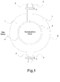
- thermoelectric generation is provided by integrating sufficient solid state semiconductor based thermoelectric modules in a clamp arrangement which comprises two substantially semi-circular, C-shaped bodies 1 each forming a clamp half, which are assembled and clamped around a fluid flow pipeline 2 carrying hot hydrocarbon fluid.
- Each C-shaped body 1 carries a flange 3 at each end, each of which is fastened to an opposite flange 3 of the other body 1 by suitable fastening means 6.
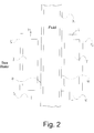
- the inner surfaces 4 of the casings of the bodies 1, when installed, are in contact with the external surface of the hot hydrocarbon fluid carrying pipeline 2, while the outer surfaces 5 of the casings of the bodies 1 are in contact with the relatively cold sea water.
- the thermoelectric modules 7 are housed within the bodies 1, there being a temperature gradient across the thermoelectric modules.
- the clamp is positioned around the pipeline 2 with the inner surfaces 4 of the casings of the bodies 1 arrangement in contact with the fluid pipeline while their external surfaces 5 are in contact with the sea water, the semiconductor based thermoelectric power generation modules 7 being housed inside the casings of the bodies 1. Electrical connections 8 are brought out to a subsea connector at the base of the arrangement (which may be permanently or temporarily connected to the load(s) using dry or wet male connectors).
- the length of the surfaces 4 in contact with the fluid pipeline 2 will depend on the output power required by the load(s), such as sensor(s) and/or other instrumentation.
- the clamp arrangement is deployable or retrievable subsea by a remotely operated vehicle (ROV).
- ROV remotely operated vehicle
- thermoelectric modules are available on the market in several physical sizes (such as 0.5 inch x 0.5 inch, 1 inch x 1 inch) which are suitable for packaging in a corrosion proof clamp arrangement. Use can be made of the relatively high mechanical strength in a compression mode (shear strength is comparatively low). When modules are installed using the above clamping method, sufficient pressure will have to be maintained on them so that a module is not “loose” so that it may easily be moved by applying a small lateral force.
- Thermoelectric modules are highly reliable components due to their solid state construction and provide long, trouble-free service.
- thermoelectric modules used in a variety of applications. Clamp-on installation simplifies retrofitting.
Landscapes
- Life Sciences & Earth Sciences (AREA)
- Engineering & Computer Science (AREA)
- Geology (AREA)
- Mining & Mineral Resources (AREA)
- Physics & Mathematics (AREA)
- Environmental & Geological Engineering (AREA)
- Fluid Mechanics (AREA)
- General Life Sciences & Earth Sciences (AREA)
- Geochemistry & Mineralogy (AREA)
- Pipeline Systems (AREA)
Priority Applications (6)
| Application Number | Priority Date | Filing Date | Title |
|---|---|---|---|
| EP11158605A EP2500511A1 (fr) | 2011-03-17 | 2011-03-17 | Fourniture d'une alimentation électrique dans une installation de puits d'hydrocarbures |
| US13/418,792 US20130014797A1 (en) | 2011-03-17 | 2012-03-13 | Supplying electrical power in a hydrocarbon well installation |
| SG10201405557QA SG10201405557QA (en) | 2011-03-17 | 2012-03-15 | Supplying electrical power in a hydrocarbon well installation |
| AU2012201572A AU2012201572A1 (en) | 2011-03-17 | 2012-03-16 | Supplying electrical power in a hydrocarbon well installation |
| CN2012100826722A CN102678088A (zh) | 2011-03-17 | 2012-03-16 | 在油气井设备中供应电功率 |
| BR102012005988-6A BR102012005988A2 (pt) | 2011-03-17 | 2012-03-16 | Método para fornecer energia elétrica em uma instalação de poço de hidrocarboneto e disposição para fornecer energia elétrica em uma instalação de poço de hidrocarboneto |
Applications Claiming Priority (1)
| Application Number | Priority Date | Filing Date | Title |
|---|---|---|---|
| EP11158605A EP2500511A1 (fr) | 2011-03-17 | 2011-03-17 | Fourniture d'une alimentation électrique dans une installation de puits d'hydrocarbures |
Publications (1)
| Publication Number | Publication Date |
|---|---|
| EP2500511A1 true EP2500511A1 (fr) | 2012-09-19 |
Family
ID=44351554
Family Applications (1)
| Application Number | Title | Priority Date | Filing Date |
|---|---|---|---|
| EP11158605A Withdrawn EP2500511A1 (fr) | 2011-03-17 | 2011-03-17 | Fourniture d'une alimentation électrique dans une installation de puits d'hydrocarbures |
Country Status (6)
| Country | Link |
|---|---|
| US (1) | US20130014797A1 (fr) |
| EP (1) | EP2500511A1 (fr) |
| CN (1) | CN102678088A (fr) |
| AU (1) | AU2012201572A1 (fr) |
| BR (1) | BR102012005988A2 (fr) |
| SG (1) | SG10201405557QA (fr) |
Cited By (2)
| Publication number | Priority date | Publication date | Assignee | Title |
|---|---|---|---|---|
| GB2585140A (en) * | 2019-06-24 | 2020-12-30 | Nemein Ltd | Downhole tool |
| NO20231022A1 (en) * | 2023-09-25 | 2025-03-26 | Affin As | Thermoelectric Energy Generation System |
Families Citing this family (3)
| Publication number | Priority date | Publication date | Assignee | Title |
|---|---|---|---|---|
| US9602045B2 (en) * | 2010-07-01 | 2017-03-21 | Chevron U.S.A. Inc. | System, apparatus, and method for monitoring a subsea flow device |
| US10366291B2 (en) * | 2017-09-09 | 2019-07-30 | Google Llc | Systems, methods, and apparatus for providing image shortcuts for an assistant application |
| NO347746B1 (en) * | 2022-03-28 | 2024-03-11 | Affin As | Assembly for generating electricity in a production well of a hot fluid |
Citations (4)
| Publication number | Priority date | Publication date | Assignee | Title |
|---|---|---|---|---|
| GB2140206A (en) * | 1983-05-20 | 1984-11-21 | British Petroleum Co Plc | Thermoelectric power generator associated with oil pipelines |
| WO1988005964A1 (fr) * | 1987-01-30 | 1988-08-11 | The University Court Of The University Of Glasgow | Dispositif generateur thermoelectrique |
| US6150601A (en) * | 1998-04-28 | 2000-11-21 | Halliburton Energy Services, Inc. | Method and apparatus for generating electric power downhole |
| WO2008042073A2 (fr) * | 2006-09-28 | 2008-04-10 | Rosemount Inc. | Ensemble de générateur thermoélectrique de pipeline |
Family Cites Families (3)
| Publication number | Priority date | Publication date | Assignee | Title |
|---|---|---|---|---|
| US4721055A (en) * | 1984-01-17 | 1988-01-26 | Underwater Systems Australia Limited | Remotely operated underwater vehicle |
| CN1330013C (zh) * | 2002-11-29 | 2007-08-01 | 诺亚公司 | 温差式发电装置 |
| CN201315556Y (zh) * | 2008-10-28 | 2009-09-23 | 林兹发 | 一种利用管道废热发电的半导体温差装置 |
-
2011
- 2011-03-17 EP EP11158605A patent/EP2500511A1/fr not_active Withdrawn
-
2012
- 2012-03-13 US US13/418,792 patent/US20130014797A1/en not_active Abandoned
- 2012-03-15 SG SG10201405557QA patent/SG10201405557QA/en unknown
- 2012-03-16 AU AU2012201572A patent/AU2012201572A1/en not_active Abandoned
- 2012-03-16 BR BR102012005988-6A patent/BR102012005988A2/pt not_active Application Discontinuation
- 2012-03-16 CN CN2012100826722A patent/CN102678088A/zh active Pending
Patent Citations (4)
| Publication number | Priority date | Publication date | Assignee | Title |
|---|---|---|---|---|
| GB2140206A (en) * | 1983-05-20 | 1984-11-21 | British Petroleum Co Plc | Thermoelectric power generator associated with oil pipelines |
| WO1988005964A1 (fr) * | 1987-01-30 | 1988-08-11 | The University Court Of The University Of Glasgow | Dispositif generateur thermoelectrique |
| US6150601A (en) * | 1998-04-28 | 2000-11-21 | Halliburton Energy Services, Inc. | Method and apparatus for generating electric power downhole |
| WO2008042073A2 (fr) * | 2006-09-28 | 2008-04-10 | Rosemount Inc. | Ensemble de générateur thermoélectrique de pipeline |
Cited By (5)
| Publication number | Priority date | Publication date | Assignee | Title |
|---|---|---|---|---|
| GB2585140A (en) * | 2019-06-24 | 2020-12-30 | Nemein Ltd | Downhole tool |
| GB2585140B (en) * | 2019-06-24 | 2023-03-22 | Nemein Ltd | Downhole tool |
| US12078033B2 (en) | 2019-06-24 | 2024-09-03 | Nemein Limited | Downhole tool |
| NO20231022A1 (en) * | 2023-09-25 | 2025-03-26 | Affin As | Thermoelectric Energy Generation System |
| WO2025071413A1 (fr) * | 2023-09-25 | 2025-04-03 | Affin As | Système de production d'énergie thermoélectrique |
Also Published As
| Publication number | Publication date |
|---|---|
| US20130014797A1 (en) | 2013-01-17 |
| CN102678088A (zh) | 2012-09-19 |
| AU2012201572A1 (en) | 2012-10-04 |
| BR102012005988A2 (pt) | 2013-11-05 |
| SG10201405557QA (en) | 2014-10-30 |
Similar Documents
| Publication | Publication Date | Title |
|---|---|---|
| CN102834583B (zh) | 用于安装和测试水下井口装备的系统 | |
| AU2005302031B2 (en) | Apparatus and method for retroactively installing sensors on marine elements | |
| US9979491B2 (en) | Subsea power-over-fiber can bus converter | |
| US9602045B2 (en) | System, apparatus, and method for monitoring a subsea flow device | |
| US10246994B2 (en) | System for communicating data via fluid lines | |
| EP2500511A1 (fr) | Fourniture d'une alimentation électrique dans une installation de puits d'hydrocarbures | |
| US9188499B2 (en) | Subsea retrievable pressure sensor | |
| CN102959429A (zh) | 监测海底流设备的系统、装置和方法 | |
| CN101983275A (zh) | 碳氢化合物抽取设施的通信系统 | |
| US11346205B2 (en) | Load and vibration monitoring on a flowline jumper | |
| GB2477714A (en) | Retrievable instrumentation module for connection to a subsea installation | |
| BRPI1104439A2 (pt) | sistema de desconexço de riser para desconectar um riser entre a superfÍcie do mar e o fundo do mar, sistema de riser marÍtimo e sistema submarino | |
| US20120247782A1 (en) | Marine riser adjustable buoyancy modules | |
| GB2498900A (en) | Transfer system | |
| US9634581B2 (en) | Piezoelectric generator for hydraulic systems | |
| GB2481304A (en) | Downhole signal coupling system | |
| US12542499B2 (en) | Electrical power system for a resource extraction system | |
| WO2009115798A1 (fr) | Transmission d'énergie et de données par tuyaux sous-marins | |
| NO20201105A1 (en) | Subsea Hydrocarbon Production System | |
| US7650942B2 (en) | Sub sea control and monitoring system | |
| NO20231022A1 (en) | Thermoelectric Energy Generation System | |
| WO2014068313A9 (fr) | Déploiement d'installation sous-marine amélioré | |
| Chimisso et al. | A New Way of Approaching Deepwater Subsea Installations |
Legal Events
| Date | Code | Title | Description |
|---|---|---|---|
| PUAI | Public reference made under article 153(3) epc to a published international application that has entered the european phase |
Free format text: ORIGINAL CODE: 0009012 |
|
| AK | Designated contracting states |
Kind code of ref document: A1 Designated state(s): AL AT BE BG CH CY CZ DE DK EE ES FI FR GB GR HR HU IE IS IT LI LT LU LV MC MK MT NL NO PL PT RO RS SE SI SK SM TR |
|
| AX | Request for extension of the european patent |
Extension state: BA ME |
|
| STAA | Information on the status of an ep patent application or granted ep patent |
Free format text: STATUS: THE APPLICATION IS DEEMED TO BE WITHDRAWN |
|
| 18D | Application deemed to be withdrawn |
Effective date: 20130320 |