EP2500518B1 - Entlüftung in einem Motor-Generatorverbindungsschafts - Google Patents
Entlüftung in einem Motor-Generatorverbindungsschafts Download PDFInfo
- Publication number
- EP2500518B1 EP2500518B1 EP12157602.9A EP12157602A EP2500518B1 EP 2500518 B1 EP2500518 B1 EP 2500518B1 EP 12157602 A EP12157602 A EP 12157602A EP 2500518 B1 EP2500518 B1 EP 2500518B1
- Authority
- EP
- European Patent Office
- Prior art keywords
- motor
- generator
- connection shaft
- assembly
- shaft
- Prior art date
- Legal status (The legal status is an assumption and is not a legal conclusion. Google has not performed a legal analysis and makes no representation as to the accuracy of the status listed.)
- Active
Links
Images

Classifications
-
- F—MECHANICAL ENGINEERING; LIGHTING; HEATING; WEAPONS; BLASTING
- F01—MACHINES OR ENGINES IN GENERAL; ENGINE PLANTS IN GENERAL; STEAM ENGINES
- F01D—NON-POSITIVE DISPLACEMENT MACHINES OR ENGINES, e.g. STEAM TURBINES
- F01D5/00—Blades; Blade-carrying members; Heating, heat-insulating, cooling or antivibration means on the blades or the members
- F01D5/02—Blade-carrying members, e.g. rotors
- F01D5/026—Shaft to shaft connections
-
- F—MECHANICAL ENGINEERING; LIGHTING; HEATING; WEAPONS; BLASTING
- F01—MACHINES OR ENGINES IN GENERAL; ENGINE PLANTS IN GENERAL; STEAM ENGINES
- F01D—NON-POSITIVE DISPLACEMENT MACHINES OR ENGINES, e.g. STEAM TURBINES
- F01D15/00—Adaptations of machines or engines for special use; Combinations of engines with devices driven thereby
- F01D15/10—Adaptations for driving, or combinations with, electric generators
-
- F—MECHANICAL ENGINEERING; LIGHTING; HEATING; WEAPONS; BLASTING
- F05—INDEXING SCHEMES RELATING TO ENGINES OR PUMPS IN VARIOUS SUBCLASSES OF CLASSES F01-F04
- F05D—INDEXING SCHEME FOR ASPECTS RELATING TO NON-POSITIVE-DISPLACEMENT MACHINES OR ENGINES, GAS-TURBINES OR JET-PROPULSION PLANTS
- F05D2260/00—Function
- F05D2260/60—Fluid transfer
- F05D2260/608—Aeration, ventilation, dehumidification or moisture removal of closed spaces
Definitions
- This disclosure relates generally to a motor-generator assembly comprising a connection shaft for a motor-generator.
- Turbomachines such as gas turbine engines, are known.
- Typical turbomachines include a compression section having large rotors.
- a motor-generator may be used to accelerate the rotors.
- the motor-generator is rotatably coupled to the turbomachine through a connection shaft. Once the turbomachine is self-sustaining, the turbomachine rotatably drives the motor-generator, which generates power that is supplied to various components.
- connection shaft is movable to a position that is decoupled from the motor-generator. In the decoupled position, the connection shaft rotates relative to the motor-generator.
- pressures inside the motor-generator can exert undesirable loads on the connection shaft when the connection shaft is disconnected from the motor-generator. The loads, and thermal energy levels resulting from the loads, can damage and degrade various components, such as the bearings that support the connection shaft or seals near the connection shaft.
- Document US 2009/0224728 A discloses a disengagement assembly for disengaging a generator from an engine.
- An example motor-generator assembly includes a motor-generator and a connection shaft.
- the connection shaft is rotatably coupled to a rotor of a gas turbine and selectively rotatably coupled to the motor-generator.
- the connection shaft establishes a communication path configured to block fluid flow when the connection shaft is coupled to the motor-generator, and to vent the motor-generator when the connection shaft is decoupled from the motor-generator.
- An example method of reducing loads on a connection shaft includes disengaging a connection shaft from a motor-generator such that the connection shaft is not rotatably coupled to the motor-generator. The method communicates a fluid away from the motor-generator through a communication path established within the connection shaft.
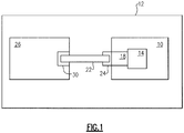
- a gas turbine engine 10 propels an aircraft 12.
- the gas turbine engine 10 is an example type of turbomachine.
- the example engine 10 includes a compressor rotor 14 that is rotatably coupled to a gearbox 18.
- a connection shaft 22 is configured to rotate together with a gearbox shaft 24.
- the compressor rotor 14 rotates the gearbox shaft 24 through the gearbox 18 during some modes of operation.
- the gearbox shaft 24 rotates the compressor rotor 14 through the gearbox 18 during other modes of operation.
- the example aircraft 12 further includes a motor-generator 26 having a journal shaft 30 that rotates together with the connection shaft 22.
- the journal shaft 30 disengages from the motor-generator 26 to decouple the connection shaft 22 from the motor-generator 26, which decouples the motor-generator 26 from the engine 10.
- the example motor-generator 26 is rotatably coupled to the engine 10 during startup of the engine 10.
- the motor-generator 26 rotates the journal shaft 30 to rotate the connection shaft 22, which drives the gearbox 18 (through the gearbox shaft 24) to rotate the compressor rotor 14.
- the gearbox 18 is used to step-up or step-down the rotational speed of the connection shaft 22 as needed.
- the motor-generator 26 continues to rotatably drive the rotor 14 until the rotor 14 has reached a speed capable of compressing enough air to sustain operation of the engine 10.
- the motor-generator 26 operates in a generator-mode after the engine 10 has reached a self-sustaining speed. In the generator-mode, the motor-generator 26 provides electrical power to other areas of the aircraft 12 through the aircraft's electrical system. Integrated drive generators and variable frequency generators are example types of the motor-generator 26.
- the engine 10 drives the motor-generator 26 in the generator-mode.
- the gearbox 18 may be used to step-up or step-down the rotational speed of the connection shaft 22 as needed.
- the motor-generator 26 generates power in a known manner when operating as a generator.
- connection shaft 22 includes splines 34 that mesh with splines 38 of the journal shaft 30.
- the splines 34 and 38 rotatably connect the journal shaft 30 and the connection shaft 22.
- the example journal shaft 30 includes a journal jaw arrangement 42 that is configured to engage a motor-generator jaw arrangement 46 extending from the motor-generator 26. Engaging the journal jaw arrangement 42 with the motor-generator jaw arrangement 46 rotatably couples the connection shaft 22 (and the journal shaft 30) with the motor-generator 26.
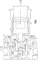
- connection shaft 22 is selectively moveable to a decoupled position, which is shown in Figure 2 .
- the journal jaw arrangement 42 is disengaged from the motor-generator jaw arrangement 46.
- the connection shaft 22 is not rotatably coupled to the motor-generator 26 when the connection shaft 22 is in the decoupled position.
- the connection shaft 22 and the journal shaft 30 rotate together relative to the motor-generator 26.
- the connection shaft 22 and the journal shaft 30 are supported on radial support bearings 48.
- the connection shaft 22 and the journal shaft 30 rotate relative to the radial support bearings 48.
- pressure within the motor-generator 26 exerts an axial force F on the journal shaft 30 and the connection shaft 22.
- the force F urges the journal shaft 30 and the connection shaft in the direction X.
- the force F is greater than the outside reaction forces on shafts 22 and 30 during some stages of flight, such as climb and cruise.
- the force F is less than the outside reaction forces on shafts 22 and 30 during other stages of flight, such as take-off and landing.
- connection shaft 22 establishes a communication path 52 that reduces pressure within the motor-generator 26 by venting to ambient. Relieving the pressure by venting reduces the loads applied to the connection shaft 22 in the direction X.
- the connection shaft 22 is biased toward the motor-generator 26 in a direction -X after pressure within the motor-generator 26 is relieved through the communication path 52. Biasing the connection shaft 22 toward the motor-generator 26 reduces frictional loading and thermal energy build-up.
- an expansion plug 56 includes an aperture 58 that establishes a portion of the communication path 52.
- the plug 56 is press fit within a central bore 62 established within the connection shaft 22.
- the aperture 58 is configured to communicate fluid from a first axial side of the plug 56 to an opposing, second axial side of the plug 56.
- the aperture 58 is coaxial with a rotational axis A of the connection shaft 22.
- connection shaft 22 When the connection shaft 22 is rotatably coupled to the motor-generator 26, the aperture 58 is plugged by a dollop of solder 66. Temperatures of the connection shaft 22 during coupled operation typically range between 200 degrees and 285 degrees Fahrenheit (93 degrees and 141 degrees Celsius), which are low enough temperatures to maintain the solder 66 in solid form.
- connection shaft 22 When the connection shaft 22 is decoupled from the motor-generator 26, temperatures in the connection shaft 22 increase due to frictional loads, for example. Temperatures of about 400 degrees Fahrenheit (204 degrees Celsius) cause the solder 66 to melt, which allows fluid to communicate to ambient from the motor-generator 26 to the bore 62 along the communication path 52. Such temperatures are typical when the connection shaft 22 is decoupled from the motor-generator 26 and rotating relative to the motor-generator 26. In some examples, a significant rise in temperature can trigger the decoupling of the connection shaft 22 from the motor-generator 26. As can be appreciated, the example communication path 52 selectively vents fluid from the motor-generator 26 due to the solder 66.
- Another portion of the communication path 52 is established by holes 70 extending from the bore 62 to an outer surface of the connection shaft 22.
- the holes 70 may be drilled in the connection shaft 22.
- fluid moves from the motor-generator 26 along the communication path 52, which extends from the aperture 58 into the bore 62 through the holes 70 to ambient.
- the communication path 52 reduces the pressures inside the connection shaft 22, which lessens the force F urging the connection shaft 22 in the direction X.
- the fluid is air in this example.
- the communication path 52 only vents the motor-generator 26 when the connection shaft 22 is decoupled from the motor-generator 26.
- the example solder 66 blocks fluid flow through the communication path 52 when the connection shaft 22 is coupled to the motor-generator 26 because the temperatures are not high enough to melt the solder 66.
- the communication path 52 relieves pressures inside the motor-generator 26 so that the force F is less than the pressure force reacting on shafts 22 and 30 outside the motor-generator 26 during all stages of flight.
- a communication path 52a within a connection shaft 22a includes the aperture 58, the bore 62, and a hole 80 that communicates the pressurized fluid from the bore 62 through the gearbox shaft 24 into the gearbox 18 of the engine.
- a plug 82 such as a screened LEE® plug is positioned within the hole 80 to limit movement of debris between the motor-generator 26 and the gearbox 18.
- the pressure of the motor-generator 26 equalizes to the pressure within the gearbox 18 due to the vent, which lessens the force F urging the connection shaft 22 in the direction X.
- connection shaft includes reducing internal pressures of the motor-generator to reduce the axial loading on a connection shaft. Another feature is biasing a connection shaft toward a motor-generator when the connection shaft is disconnected from the motor-generator. The connection shaft is biased toward the motor-generator at all stages of the flight envelope rather than alternating between a positive bias and a negative bias.
Landscapes
- Engineering & Computer Science (AREA)
- Mechanical Engineering (AREA)
- General Engineering & Computer Science (AREA)
- Connection Of Motors, Electrical Generators, Mechanical Devices, And The Like (AREA)
Claims (14)
- Motor-Generatorbaugruppe, die Folgendes umfasst:einen Motor-Generator (26), gekennzeichnet durch eine Turbomaschinenverbindungsschaftbaugruppe, die Folgendes umfasst:einen Verbindungsschaft (22, 22a), der dazu konfiguriert ist, einen Turbomaschinenrotor (14) und den Motor-Generator selektiv rotierbar zu koppeln, wobei der Verbindungsschaft einen Verbindungspfad (52, 52a) erstellt, der dazu konfiguriert ist, Fluidströmung zu blockieren, wenn der Verbindungsschaft mit dem Motor-Generator gekoppelt ist, undden Motor-Generator zu entlüften, wenn der Verbindungsschaft von dem Motor-Generator entkoppelt ist.
- Motor-Generatorbaugruppe nach Anspruch 1, wobei die Turbomaschinenverbindungsschaftbaugruppe angeordnet ist, um Fluid von dem Verbindungspfad zu einem Turbinentriebwerk zu bewegen, das einen Turbomaschinenrotor aufweist.
- Motor-Generatorbaugruppe nach Anspruch 1, wobei die Turbomaschinenverbindungsschaftbaugruppe angeordnet ist, um Fluid von dem Verbindungspfad in die Umgebung zu bewegen.
- Motor-Generatorbaugruppe nach Anspruch 1, 2 oder 3, wobei:die Turbomaschinenverbindungsschaftbaugruppe ferner Folgendes umfasst:einen Expansionsstopfen (56), der innerhalb einer sich axial erstreckenden Bohrung (62) angeordnet ist, die innerhalb des Verbindungsschafts erstellt ist, wobei der Expansionsstopfen eine Öffnung (58) definiert, die Fluid von einer ersten axialen Seite des Expansionsstopfens zu einer gegenüberliegenden, zweiten axiale Seite des Expansionsstopfens verbinden kann.
- Motor-Generatorbaugruppe nach Anspruch 4, wobei die Öffnung (58) koaxial mit dem Verbindungsschaft (22, 22a) ist.
- Motor-Generatorbaugruppe nach Anspruch 4, wobei:die Turbomaschinenverbindungsschaftbaugruppe einen Klumpen (66) aus Lötmetall beinhaltet, der sich von einer ersten Position, wenn der Verbindungsschaft und Motor-Generator rotierbar gekoppelt sind, in eine zweite Position, wenn der Verbindungsschaft und der Motor-Generator rotierbar entkoppelt sind, bewegt, wobei der Klumpen aus Lötmetall dazu konfiguriert ist, Strömung durch die Öffnung in der ersten Position zu begrenzen und in der zweiten Position zu ermöglichen.
- Motor-Generatorbaugruppe nach Anspruch 1, 2, 3, 4, oder 5, wobei:die Turbomaschinenverbindungsschaftbaugruppe einen abgeschirmten Stopfen (82) beinhaltet, der innerhalb eines Abschnitts des Verbindungspfads (52a) angeordnet ist, wobei der Verbindungspfad das Fluid mit einem Triebwerk (10) verbinden kann.
- Motor-Generatorbaugruppe nach Anspruch 1, 2, 3, 4, oder 5, wobei der Verbindungsschaft mindestens ein Loch (70) definiert, das sich von einer sich axial erstreckenden Bohrung zu einer radialen Außenfläche des Verbindungschafts erstreckt, wobei der Verbindungspfad vorzugsweise Abschnitte der Bohrung (62), eine Öffnung (58) und das Loch (70) umfasst.
- Motor-Generatorbaugruppe nach einem der vorstehenden Ansprüche, wobei:die Turbomaschinenverbindungsschaftbaugruppe einen Lagerzapfenschaft (30) beinhaltet, der einen Endabschnitt des Verbindungsschafts (22, 22a) aufnimmt, wobei der Verbindungsschaft dazu konfiguriert ist, den Lagerzapfenschaft zu rotieren, wobei der Lagerzapfenschaft dazu konfiguriert ist, den Verbindungsschaft mit dem Motor-Generator (26) selektiv rotierbar zu koppeln.
- Motor-Generatorbaugruppe nach einem der vorstehenden Ansprüche, wobei der Motor-Generator (26) ein variabler Frequenzgenerator ist.
- Motor-Generatorbaugruppe nach Anspruch 1, eine radiale Stützlager(48)-Anordnung beinhaltend, die dazu konfiguriert ist, den Verbindungsschaft zu stützen, wobei der Verbindungsschaft mit der radialen Stützlageranordnung rotiert, wenn der Verbindungsschaft mit dem Motor-Generator gekoppelt ist und der Lagerzapfenschaft relativ zu der radialen Stützlagerung rotiert, wenn der Verbindungsschaft von dem Motor-Generator entkoppelt ist.
- Verfahren zum Reduzieren von Belastung auf einem Verbindungsschaft (22, 22a), wobei das Verfahren Folgendes umfasst:Lösen eines Verbindungsschafts von einem Motor-Generator (26) derart, dass der Verbindungsschaft nicht rotierbar mit dem Motor-Generator gekoppelt ist; undVerbinden eines Fluids von dem Motor-Generator (26) weg durch einen Verbindungspfad (52, 52a), der innerhalb des Verbindungsschafts erstellt ist.
- Verfahren nach Anspruch 12, wobei das Lösen das Lösen von Backen (42) eines Lagerzapfenschafts mit entsprechenden Backen (46) des Motor-Generators umfasst.
- Verfahren nach Anspruch 12 oder 13, wobei das Verfahren an einem Luftfahrzeug (12) durchgeführt wird und der Verbindungsschaft axial in Richtung des Motor-Generators während aller Flugphasen des Luftfahrzeugs vorgespannt ist.
Applications Claiming Priority (1)
| Application Number | Priority Date | Filing Date | Title |
|---|---|---|---|
| US13/047,950 US8998564B2 (en) | 2011-03-15 | 2011-03-15 | Motor-generator connection shaft vent |
Publications (3)
| Publication Number | Publication Date |
|---|---|
| EP2500518A2 EP2500518A2 (de) | 2012-09-19 |
| EP2500518A3 EP2500518A3 (de) | 2017-09-06 |
| EP2500518B1 true EP2500518B1 (de) | 2019-02-06 |
Family
ID=45811303
Family Applications (1)
| Application Number | Title | Priority Date | Filing Date |
|---|---|---|---|
| EP12157602.9A Active EP2500518B1 (de) | 2011-03-15 | 2012-02-29 | Entlüftung in einem Motor-Generatorverbindungsschafts |
Country Status (2)
| Country | Link |
|---|---|
| US (1) | US8998564B2 (de) |
| EP (1) | EP2500518B1 (de) |
Families Citing this family (7)
| Publication number | Priority date | Publication date | Assignee | Title |
|---|---|---|---|---|
| DE102012206189A1 (de) * | 2012-04-16 | 2013-10-17 | Robert Bosch Gmbh | Elektrische Maschine und Verfahren zum Betreiben einer elektrischen Maschine |
| US20140008170A1 (en) * | 2012-07-06 | 2014-01-09 | Henry R. Vanderzyden | Integrated drive generator disconnect assembly |
| US10056805B2 (en) | 2015-10-02 | 2018-08-21 | Hamilton Sundstrand Corporation | Venting generator assemblies |
| US9784380B2 (en) * | 2015-10-12 | 2017-10-10 | Hamilton Sundstrand Corporation | Valve assembly for variable frequency generator and method of sealing |
| JP2019097091A (ja) * | 2017-11-27 | 2019-06-20 | シャープ株式会社 | 電子機器、画像形成装置、電子機器の制御方法及びプログラム |
| GB2572427B (en) * | 2018-03-29 | 2023-01-11 | Safran Electrical & Power | A generator having a disconnect mechanism |
| FR3124541B1 (fr) * | 2021-06-28 | 2023-11-10 | Safran Aircraft Engines | Turbomachine comprenant une machine électrique à une extrémité arrière de turbine |
Family Cites Families (14)
| Publication number | Priority date | Publication date | Assignee | Title |
|---|---|---|---|---|
| US3835722A (en) | 1973-03-28 | 1974-09-17 | Caterpillar Tractor Co | Quick disconnect device for power trains |
| US4269293A (en) | 1979-03-05 | 1981-05-26 | The Garrett Corporation | Engine accessory disconnect |
| US4588322A (en) | 1984-06-22 | 1986-05-13 | A. Lakin & Sons, Inc. | Motor shaft bearing support and disconnect |
| US4685550A (en) | 1985-09-26 | 1987-08-11 | Sundstrand Corporation | Quick disconnect mechanism |
| US5174109A (en) | 1990-10-25 | 1992-12-29 | Sundstrand Corporation | Clutch to disconnect loads during turbine start-up |
| US5103949A (en) | 1990-11-08 | 1992-04-14 | Sundstrand Corporation | Thermal disconnect |
| US5901013A (en) | 1997-08-11 | 1999-05-04 | International Business Machines Corporation | Fluid spindle bearing vent |
| US6725643B1 (en) | 2001-06-19 | 2004-04-27 | Marius Paul | High efficiency gas turbine power generator systems |
| US6732529B2 (en) | 2001-11-16 | 2004-05-11 | Pratt & Whitney Canada Corp. | Off loading clutch for gas turbine engine starting |
| GB0329703D0 (en) | 2003-12-22 | 2004-01-28 | Goodrich Control Sys Ltd | Drive disconnect device |
| US7687928B2 (en) * | 2006-06-14 | 2010-03-30 | Smiths Aerospace, Llc | Dual-structured aircraft engine starter/generator |
| US7896147B2 (en) * | 2008-03-04 | 2011-03-01 | Honeywell International Inc. | Application of eddy current braking system for use in a gearbox/generator mechanical disconnect |
| US8963391B2 (en) * | 2009-05-06 | 2015-02-24 | Hamilton Sundstrand Corporation | Decoupler shaft for high speed generator |
| US8568089B2 (en) * | 2010-06-03 | 2013-10-29 | Hamilton Sundstrand Corporation | Gear arrangement |
-
2011
- 2011-03-15 US US13/047,950 patent/US8998564B2/en active Active
-
2012
- 2012-02-29 EP EP12157602.9A patent/EP2500518B1/de active Active
Non-Patent Citations (1)
| Title |
|---|
| None * |
Also Published As
| Publication number | Publication date |
|---|---|
| EP2500518A3 (de) | 2017-09-06 |
| US8998564B2 (en) | 2015-04-07 |
| US20120237337A1 (en) | 2012-09-20 |
| EP2500518A2 (de) | 2012-09-19 |
Similar Documents
| Publication | Publication Date | Title |
|---|---|---|
| EP2500518B1 (de) | Entlüftung in einem Motor-Generatorverbindungsschafts | |
| EP2402560B1 (de) | Wellenverbindungsanordnung | |
| US11466697B2 (en) | Fan module comprising variable-pitch blades | |
| EP2362081B1 (de) | System zur Druckluftbeaufschlagung von Lagergehäusen und zur Wellenbelüftung | |
| EP2935839B1 (de) | Turbinenmotorgetriebegehäuse mit mehreren sicherungsanschlüssen | |
| US10352247B2 (en) | Low spool starter system for gas turbine engine | |
| EP3040567B1 (de) | Lageranordnung mit zwei wälzlagern und druckkammern zum vorspannen der wälzlager und zum gleichmässigen verteilen der axiallast auf beide lager | |
| CN108952970B (zh) | 行星齿轮系统和空气涡轮起动器 | |
| US8573922B2 (en) | Bearing support | |
| EP2935840B1 (de) | Halterung mit einer axialen aufwärtsverbindung zum verbinden eines getriebes mit einem turbinenmotorgehäuse | |
| EP3536901B1 (de) | Schubsteuerung eines gelagerten rotors | |
| US20100284794A1 (en) | Low pressure turbine rotor disk | |
| CN109477512B (zh) | 用于气体轴承组件的流体填充式阻尼器 | |
| EP3236051A1 (de) | Ölfreier gasturbinenmotor | |
| US20070084185A1 (en) | Gas turbine engine assembly and methods of assembling same | |
| EP2855889B1 (de) | Dichtungsfläche für die statikstruktur eines gasturbinentriebwerks | |
| CN1952368A (zh) | 燃气轮机装置及其装配方法 | |
| US20180209479A1 (en) | Bearing | |
| US20150233386A1 (en) | First stage turbine housing for an air cycle machine | |
| US11131248B2 (en) | Planetary gear, splined sleeve, gas turbine engine with a planetary gear and method for manufacturing a planetary gear | |
| US11970981B2 (en) | Planetary gearbox | |
| EP2964907B1 (de) | Gasturbinentriebwerk mit spaltregelung | |
| US10502144B2 (en) | Gas turbine engine with a geared turbofan arrangement | |
| CN117999223A (zh) | 用于飞行器涡轮发动机的模块 | |
| WO2026087836A1 (fr) | Turbomachine equipee d'une machine electrique et de moyens d'accouplement entre un arbre de la turbomachine et un arbre relie a la machine electrique |
Legal Events
| Date | Code | Title | Description |
|---|---|---|---|
| PUAI | Public reference made under article 153(3) epc to a published international application that has entered the european phase |
Free format text: ORIGINAL CODE: 0009012 |
|
| AK | Designated contracting states |
Kind code of ref document: A2 Designated state(s): AL AT BE BG CH CY CZ DE DK EE ES FI FR GB GR HR HU IE IS IT LI LT LU LV MC MK MT NL NO PL PT RO RS SE SI SK SM TR |
|
| AX | Request for extension of the european patent |
Extension state: BA ME |
|
| PUAL | Search report despatched |
Free format text: ORIGINAL CODE: 0009013 |
|
| AK | Designated contracting states |
Kind code of ref document: A3 Designated state(s): AL AT BE BG CH CY CZ DE DK EE ES FI FR GB GR HR HU IE IS IT LI LT LU LV MC MK MT NL NO PL PT RO RS SE SI SK SM TR |
|
| AX | Request for extension of the european patent |
Extension state: BA ME |
|
| RIC1 | Information provided on ipc code assigned before grant |
Ipc: F01D 15/10 20060101ALI20170803BHEP Ipc: F01D 5/02 20060101AFI20170803BHEP |
|
| STAA | Information on the status of an ep patent application or granted ep patent |
Free format text: STATUS: REQUEST FOR EXAMINATION WAS MADE |
|
| 17P | Request for examination filed |
Effective date: 20180125 |
|
| RBV | Designated contracting states (corrected) |
Designated state(s): AL AT BE BG CH CY CZ DE DK EE ES FI FR GB GR HR HU IE IS IT LI LT LU LV MC MK MT NL NO PL PT RO RS SE SI SK SM TR |
|
| GRAP | Despatch of communication of intention to grant a patent |
Free format text: ORIGINAL CODE: EPIDOSNIGR1 |
|
| STAA | Information on the status of an ep patent application or granted ep patent |
Free format text: STATUS: GRANT OF PATENT IS INTENDED |
|
| INTG | Intention to grant announced |
Effective date: 20180814 |
|
| GRAS | Grant fee paid |
Free format text: ORIGINAL CODE: EPIDOSNIGR3 |
|
| GRAA | (expected) grant |
Free format text: ORIGINAL CODE: 0009210 |
|
| STAA | Information on the status of an ep patent application or granted ep patent |
Free format text: STATUS: THE PATENT HAS BEEN GRANTED |
|
| AK | Designated contracting states |
Kind code of ref document: B1 Designated state(s): AL AT BE BG CH CY CZ DE DK EE ES FI FR GB GR HR HU IE IS IT LI LT LU LV MC MK MT NL NO PL PT RO RS SE SI SK SM TR |
|
| REG | Reference to a national code |
Ref country code: GB Ref legal event code: FG4D |
|
| REG | Reference to a national code |
Ref country code: CH Ref legal event code: EP Ref country code: AT Ref legal event code: REF Ref document number: 1095035 Country of ref document: AT Kind code of ref document: T Effective date: 20190215 |
|
| REG | Reference to a national code |
Ref country code: DE Ref legal event code: R096 Ref document number: 602012056426 Country of ref document: DE |
|
| REG | Reference to a national code |
Ref country code: IE Ref legal event code: FG4D |
|
| REG | Reference to a national code |
Ref country code: NL Ref legal event code: MP Effective date: 20190206 |
|
| REG | Reference to a national code |
Ref country code: LT Ref legal event code: MG4D |
|
| PG25 | Lapsed in a contracting state [announced via postgrant information from national office to epo] |
Ref country code: NL Free format text: LAPSE BECAUSE OF FAILURE TO SUBMIT A TRANSLATION OF THE DESCRIPTION OR TO PAY THE FEE WITHIN THE PRESCRIBED TIME-LIMIT Effective date: 20190206 Ref country code: LT Free format text: LAPSE BECAUSE OF FAILURE TO SUBMIT A TRANSLATION OF THE DESCRIPTION OR TO PAY THE FEE WITHIN THE PRESCRIBED TIME-LIMIT Effective date: 20190206 Ref country code: FI Free format text: LAPSE BECAUSE OF FAILURE TO SUBMIT A TRANSLATION OF THE DESCRIPTION OR TO PAY THE FEE WITHIN THE PRESCRIBED TIME-LIMIT Effective date: 20190206 Ref country code: NO Free format text: LAPSE BECAUSE OF FAILURE TO SUBMIT A TRANSLATION OF THE DESCRIPTION OR TO PAY THE FEE WITHIN THE PRESCRIBED TIME-LIMIT Effective date: 20190506 Ref country code: PT Free format text: LAPSE BECAUSE OF FAILURE TO SUBMIT A TRANSLATION OF THE DESCRIPTION OR TO PAY THE FEE WITHIN THE PRESCRIBED TIME-LIMIT Effective date: 20190606 Ref country code: SE Free format text: LAPSE BECAUSE OF FAILURE TO SUBMIT A TRANSLATION OF THE DESCRIPTION OR TO PAY THE FEE WITHIN THE PRESCRIBED TIME-LIMIT Effective date: 20190206 |
|
| REG | Reference to a national code |
Ref country code: AT Ref legal event code: MK05 Ref document number: 1095035 Country of ref document: AT Kind code of ref document: T Effective date: 20190206 |
|
| PG25 | Lapsed in a contracting state [announced via postgrant information from national office to epo] |
Ref country code: GR Free format text: LAPSE BECAUSE OF FAILURE TO SUBMIT A TRANSLATION OF THE DESCRIPTION OR TO PAY THE FEE WITHIN THE PRESCRIBED TIME-LIMIT Effective date: 20190507 Ref country code: BG Free format text: LAPSE BECAUSE OF FAILURE TO SUBMIT A TRANSLATION OF THE DESCRIPTION OR TO PAY THE FEE WITHIN THE PRESCRIBED TIME-LIMIT Effective date: 20190506 Ref country code: HR Free format text: LAPSE BECAUSE OF FAILURE TO SUBMIT A TRANSLATION OF THE DESCRIPTION OR TO PAY THE FEE WITHIN THE PRESCRIBED TIME-LIMIT Effective date: 20190206 Ref country code: IS Free format text: LAPSE BECAUSE OF FAILURE TO SUBMIT A TRANSLATION OF THE DESCRIPTION OR TO PAY THE FEE WITHIN THE PRESCRIBED TIME-LIMIT Effective date: 20190606 Ref country code: RS Free format text: LAPSE BECAUSE OF FAILURE TO SUBMIT A TRANSLATION OF THE DESCRIPTION OR TO PAY THE FEE WITHIN THE PRESCRIBED TIME-LIMIT Effective date: 20190206 Ref country code: LV Free format text: LAPSE BECAUSE OF FAILURE TO SUBMIT A TRANSLATION OF THE DESCRIPTION OR TO PAY THE FEE WITHIN THE PRESCRIBED TIME-LIMIT Effective date: 20190206 |
|
| REG | Reference to a national code |
Ref country code: DE Ref legal event code: R119 Ref document number: 602012056426 Country of ref document: DE |
|
| REG | Reference to a national code |
Ref country code: CH Ref legal event code: PL |
|
| PG25 | Lapsed in a contracting state [announced via postgrant information from national office to epo] |
Ref country code: SK Free format text: LAPSE BECAUSE OF FAILURE TO SUBMIT A TRANSLATION OF THE DESCRIPTION OR TO PAY THE FEE WITHIN THE PRESCRIBED TIME-LIMIT Effective date: 20190206 Ref country code: LU Free format text: LAPSE BECAUSE OF NON-PAYMENT OF DUE FEES Effective date: 20190228 Ref country code: CZ Free format text: LAPSE BECAUSE OF FAILURE TO SUBMIT A TRANSLATION OF THE DESCRIPTION OR TO PAY THE FEE WITHIN THE PRESCRIBED TIME-LIMIT Effective date: 20190206 Ref country code: RO Free format text: LAPSE BECAUSE OF FAILURE TO SUBMIT A TRANSLATION OF THE DESCRIPTION OR TO PAY THE FEE WITHIN THE PRESCRIBED TIME-LIMIT Effective date: 20190206 Ref country code: ES Free format text: LAPSE BECAUSE OF FAILURE TO SUBMIT A TRANSLATION OF THE DESCRIPTION OR TO PAY THE FEE WITHIN THE PRESCRIBED TIME-LIMIT Effective date: 20190206 Ref country code: AL Free format text: LAPSE BECAUSE OF FAILURE TO SUBMIT A TRANSLATION OF THE DESCRIPTION OR TO PAY THE FEE WITHIN THE PRESCRIBED TIME-LIMIT Effective date: 20190206 Ref country code: EE Free format text: LAPSE BECAUSE OF FAILURE TO SUBMIT A TRANSLATION OF THE DESCRIPTION OR TO PAY THE FEE WITHIN THE PRESCRIBED TIME-LIMIT Effective date: 20190206 Ref country code: DK Free format text: LAPSE BECAUSE OF FAILURE TO SUBMIT A TRANSLATION OF THE DESCRIPTION OR TO PAY THE FEE WITHIN THE PRESCRIBED TIME-LIMIT Effective date: 20190206 Ref country code: IT Free format text: LAPSE BECAUSE OF FAILURE TO SUBMIT A TRANSLATION OF THE DESCRIPTION OR TO PAY THE FEE WITHIN THE PRESCRIBED TIME-LIMIT Effective date: 20190206 |
|
| REG | Reference to a national code |
Ref country code: BE Ref legal event code: MM Effective date: 20190228 |
|
| REG | Reference to a national code |
Ref country code: IE Ref legal event code: MM4A |
|
| PG25 | Lapsed in a contracting state [announced via postgrant information from national office to epo] |
Ref country code: SM Free format text: LAPSE BECAUSE OF FAILURE TO SUBMIT A TRANSLATION OF THE DESCRIPTION OR TO PAY THE FEE WITHIN THE PRESCRIBED TIME-LIMIT Effective date: 20190206 Ref country code: PL Free format text: LAPSE BECAUSE OF FAILURE TO SUBMIT A TRANSLATION OF THE DESCRIPTION OR TO PAY THE FEE WITHIN THE PRESCRIBED TIME-LIMIT Effective date: 20190206 |
|
| PLBE | No opposition filed within time limit |
Free format text: ORIGINAL CODE: 0009261 |
|
| STAA | Information on the status of an ep patent application or granted ep patent |
Free format text: STATUS: NO OPPOSITION FILED WITHIN TIME LIMIT |
|
| PG25 | Lapsed in a contracting state [announced via postgrant information from national office to epo] |
Ref country code: LI Free format text: LAPSE BECAUSE OF NON-PAYMENT OF DUE FEES Effective date: 20190228 Ref country code: CH Free format text: LAPSE BECAUSE OF NON-PAYMENT OF DUE FEES Effective date: 20190228 Ref country code: MC Free format text: LAPSE BECAUSE OF FAILURE TO SUBMIT A TRANSLATION OF THE DESCRIPTION OR TO PAY THE FEE WITHIN THE PRESCRIBED TIME-LIMIT Effective date: 20190206 Ref country code: AT Free format text: LAPSE BECAUSE OF FAILURE TO SUBMIT A TRANSLATION OF THE DESCRIPTION OR TO PAY THE FEE WITHIN THE PRESCRIBED TIME-LIMIT Effective date: 20190206 |
|
| 26N | No opposition filed |
Effective date: 20191107 |
|
| PG25 | Lapsed in a contracting state [announced via postgrant information from national office to epo] |
Ref country code: IE Free format text: LAPSE BECAUSE OF NON-PAYMENT OF DUE FEES Effective date: 20190228 Ref country code: DE Free format text: LAPSE BECAUSE OF NON-PAYMENT OF DUE FEES Effective date: 20190903 |
|
| PG25 | Lapsed in a contracting state [announced via postgrant information from national office to epo] |
Ref country code: SI Free format text: LAPSE BECAUSE OF FAILURE TO SUBMIT A TRANSLATION OF THE DESCRIPTION OR TO PAY THE FEE WITHIN THE PRESCRIBED TIME-LIMIT Effective date: 20190206 Ref country code: BE Free format text: LAPSE BECAUSE OF NON-PAYMENT OF DUE FEES Effective date: 20190228 |
|
| PG25 | Lapsed in a contracting state [announced via postgrant information from national office to epo] |
Ref country code: TR Free format text: LAPSE BECAUSE OF FAILURE TO SUBMIT A TRANSLATION OF THE DESCRIPTION OR TO PAY THE FEE WITHIN THE PRESCRIBED TIME-LIMIT Effective date: 20190206 |
|
| PG25 | Lapsed in a contracting state [announced via postgrant information from national office to epo] |
Ref country code: MT Free format text: LAPSE BECAUSE OF NON-PAYMENT OF DUE FEES Effective date: 20190228 |
|
| PG25 | Lapsed in a contracting state [announced via postgrant information from national office to epo] |
Ref country code: CY Free format text: LAPSE BECAUSE OF FAILURE TO SUBMIT A TRANSLATION OF THE DESCRIPTION OR TO PAY THE FEE WITHIN THE PRESCRIBED TIME-LIMIT Effective date: 20190206 |
|
| PG25 | Lapsed in a contracting state [announced via postgrant information from national office to epo] |
Ref country code: HU Free format text: LAPSE BECAUSE OF FAILURE TO SUBMIT A TRANSLATION OF THE DESCRIPTION OR TO PAY THE FEE WITHIN THE PRESCRIBED TIME-LIMIT; INVALID AB INITIO Effective date: 20120229 |
|
| PG25 | Lapsed in a contracting state [announced via postgrant information from national office to epo] |
Ref country code: MK Free format text: LAPSE BECAUSE OF FAILURE TO SUBMIT A TRANSLATION OF THE DESCRIPTION OR TO PAY THE FEE WITHIN THE PRESCRIBED TIME-LIMIT Effective date: 20190206 |
|
| P01 | Opt-out of the competence of the unified patent court (upc) registered |
Effective date: 20230522 |
|
| PGFP | Annual fee paid to national office [announced via postgrant information from national office to epo] |
Ref country code: GB Payment date: 20260121 Year of fee payment: 15 |
|
| PGFP | Annual fee paid to national office [announced via postgrant information from national office to epo] |
Ref country code: FR Payment date: 20260121 Year of fee payment: 15 |