EP2500523A2 - Cadre et procédé de refroidissement du cadre - Google Patents
Cadre et procédé de refroidissement du cadre Download PDFInfo
- Publication number
- EP2500523A2 EP2500523A2 EP12158160A EP12158160A EP2500523A2 EP 2500523 A2 EP2500523 A2 EP 2500523A2 EP 12158160 A EP12158160 A EP 12158160A EP 12158160 A EP12158160 A EP 12158160A EP 2500523 A2 EP2500523 A2 EP 2500523A2
- Authority
- EP
- European Patent Office
- Prior art keywords
- aft frame
- cooling
- coolant
- passage
- flow path
- Prior art date
- Legal status (The legal status is an assumption and is not a legal conclusion. Google has not performed a legal analysis and makes no representation as to the accuracy of the status listed.)
- Granted
Links
Images


Classifications
-
- F—MECHANICAL ENGINEERING; LIGHTING; HEATING; WEAPONS; BLASTING
- F01—MACHINES OR ENGINES IN GENERAL; ENGINE PLANTS IN GENERAL; STEAM ENGINES
- F01D—NON-POSITIVE DISPLACEMENT MACHINES OR ENGINES, e.g. STEAM TURBINES
- F01D9/00—Stators
- F01D9/02—Nozzles; Nozzle boxes; Stator blades; Guide conduits, e.g. individual nozzles
- F01D9/023—Transition ducts between combustor cans and first stage of the turbine in gas-turbine engines; their cooling or sealings
-
- F—MECHANICAL ENGINEERING; LIGHTING; HEATING; WEAPONS; BLASTING
- F01—MACHINES OR ENGINES IN GENERAL; ENGINE PLANTS IN GENERAL; STEAM ENGINES
- F01D—NON-POSITIVE DISPLACEMENT MACHINES OR ENGINES, e.g. STEAM TURBINES
- F01D25/00—Component parts, details, or accessories, not provided for in, or of interest apart from, other groups
- F01D25/08—Cooling; Heating; Heat-insulation
- F01D25/12—Cooling
-
- F—MECHANICAL ENGINEERING; LIGHTING; HEATING; WEAPONS; BLASTING
- F02—COMBUSTION ENGINES; HOT-GAS OR COMBUSTION-PRODUCT ENGINE PLANTS
- F02C—GAS-TURBINE PLANTS; AIR INTAKES FOR JET-PROPULSION PLANTS; CONTROLLING FUEL SUPPLY IN AIR-BREATHING JET-PROPULSION PLANTS
- F02C7/00—Features, components parts, details or accessories, not provided for in, or of interest apart form groups F02C1/00 - F02C6/00; Air intakes for jet-propulsion plants
- F02C7/20—Mounting or supporting of plant; Accommodating heat expansion or creep
-
- F—MECHANICAL ENGINEERING; LIGHTING; HEATING; WEAPONS; BLASTING
- F05—INDEXING SCHEMES RELATING TO ENGINES OR PUMPS IN VARIOUS SUBCLASSES OF CLASSES F01-F04
- F05D—INDEXING SCHEME FOR ASPECTS RELATING TO NON-POSITIVE-DISPLACEMENT MACHINES OR ENGINES, GAS-TURBINES OR JET-PROPULSION PLANTS
- F05D2260/00—Function
- F05D2260/20—Heat transfer, e.g. cooling
- F05D2260/201—Heat transfer, e.g. cooling by impingement of a fluid
-
- F—MECHANICAL ENGINEERING; LIGHTING; HEATING; WEAPONS; BLASTING
- F05—INDEXING SCHEMES RELATING TO ENGINES OR PUMPS IN VARIOUS SUBCLASSES OF CLASSES F01-F04
- F05D—INDEXING SCHEME FOR ASPECTS RELATING TO NON-POSITIVE-DISPLACEMENT MACHINES OR ENGINES, GAS-TURBINES OR JET-PROPULSION PLANTS
- F05D2260/00—Function
- F05D2260/20—Heat transfer, e.g. cooling
- F05D2260/202—Heat transfer, e.g. cooling by film cooling
-
- F—MECHANICAL ENGINEERING; LIGHTING; HEATING; WEAPONS; BLASTING
- F05—INDEXING SCHEMES RELATING TO ENGINES OR PUMPS IN VARIOUS SUBCLASSES OF CLASSES F01-F04
- F05D—INDEXING SCHEME FOR ASPECTS RELATING TO NON-POSITIVE-DISPLACEMENT MACHINES OR ENGINES, GAS-TURBINES OR JET-PROPULSION PLANTS
- F05D2260/00—Function
- F05D2260/20—Heat transfer, e.g. cooling
- F05D2260/232—Heat transfer, e.g. cooling characterized by the cooling medium
- F05D2260/2322—Heat transfer, e.g. cooling characterized by the cooling medium steam
-
- F—MECHANICAL ENGINEERING; LIGHTING; HEATING; WEAPONS; BLASTING
- F23—COMBUSTION APPARATUS; COMBUSTION PROCESSES
- F23R—GENERATING COMBUSTION PRODUCTS OF HIGH PRESSURE OR HIGH VELOCITY, e.g. GAS-TURBINE COMBUSTION CHAMBERS
- F23R2900/00—Special features of, or arrangements for continuous combustion chambers; Combustion processes therefor
- F23R2900/00012—Details of sealing devices
-
- F—MECHANICAL ENGINEERING; LIGHTING; HEATING; WEAPONS; BLASTING
- F23—COMBUSTION APPARATUS; COMBUSTION PROCESSES
- F23R—GENERATING COMBUSTION PRODUCTS OF HIGH PRESSURE OR HIGH VELOCITY, e.g. GAS-TURBINE COMBUSTION CHAMBERS
- F23R2900/00—Special features of, or arrangements for continuous combustion chambers; Combustion processes therefor
- F23R2900/03041—Effusion cooled combustion chamber walls or domes
-
- F—MECHANICAL ENGINEERING; LIGHTING; HEATING; WEAPONS; BLASTING
- F23—COMBUSTION APPARATUS; COMBUSTION PROCESSES
- F23R—GENERATING COMBUSTION PRODUCTS OF HIGH PRESSURE OR HIGH VELOCITY, e.g. GAS-TURBINE COMBUSTION CHAMBERS
- F23R2900/00—Special features of, or arrangements for continuous combustion chambers; Combustion processes therefor
- F23R2900/03042—Film cooled combustion chamber walls or domes
-
- F—MECHANICAL ENGINEERING; LIGHTING; HEATING; WEAPONS; BLASTING
- F23—COMBUSTION APPARATUS; COMBUSTION PROCESSES
- F23R—GENERATING COMBUSTION PRODUCTS OF HIGH PRESSURE OR HIGH VELOCITY, e.g. GAS-TURBINE COMBUSTION CHAMBERS
- F23R2900/00—Special features of, or arrangements for continuous combustion chambers; Combustion processes therefor
- F23R2900/03043—Convection cooled combustion chamber walls with means for guiding the cooling air flow
-
- F—MECHANICAL ENGINEERING; LIGHTING; HEATING; WEAPONS; BLASTING
- F23—COMBUSTION APPARATUS; COMBUSTION PROCESSES
- F23R—GENERATING COMBUSTION PRODUCTS OF HIGH PRESSURE OR HIGH VELOCITY, e.g. GAS-TURBINE COMBUSTION CHAMBERS
- F23R2900/00—Special features of, or arrangements for continuous combustion chambers; Combustion processes therefor
- F23R2900/03044—Impingement cooled combustion chamber walls or subassemblies
-
- F—MECHANICAL ENGINEERING; LIGHTING; HEATING; WEAPONS; BLASTING
- F23—COMBUSTION APPARATUS; COMBUSTION PROCESSES
- F23R—GENERATING COMBUSTION PRODUCTS OF HIGH PRESSURE OR HIGH VELOCITY, e.g. GAS-TURBINE COMBUSTION CHAMBERS
- F23R3/00—Continuous combustion chambers using liquid or gaseous fuel
- F23R3/42—Continuous combustion chambers using liquid or gaseous fuel characterised by the arrangement or form of the flame tubes or combustion chambers
- F23R3/60—Support structures; Attaching or mounting means
Definitions
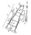
- the present disclosure relates in general to combustors, and more particularly to aft frames in combustors. Specifically, the present disclosure relates to aft frames with novel cooling features and novel methods for cooling aft frames.
- the invention resides in an aft frame for a transition piece in a combustor, the combustor including the transition piece and an impingement sleeve at least partially defining a flow path therebetween.
- the aft frame includes a body and a generally radially extending cooling passage defined in the body, the cooling passage comprising a first end configured to accept a coolant.
- the aft frame further includes an exhaust passage defined in the body, the exhaust passage including a first end in communication with the cooling passage and a second end configured for communication with the flow path for flowing the coolant therethrough.
- the system 10 comprises a compressor section 12 for pressurizing a working fluid, discussed below, that is flowing through the system 10.
- Pressurized working fluid discharged from the compressor section 12 flows into a combustor section 14, which is generally characterized by a plurality of combustors 16 (only one of which is illustrated in FIG. 1 ) disposed in an annular array about an axis of the system 10.
- the working fluid entering the combustor section 14 is mixed with fuel, such as natural gas or another suitable liquid or gas, and combusted. Hot gases of combustion flow from each combustor 16 to a turbine section 18 to drive the system 10 and generate power.
- the combustor 16 may further include a fuel nozzle 40 or a plurality of fuel nozzles 40. Fuel may be supplied to the fuel nozzles 40 by one or more manifolds (not shown). As discussed below, the fuel nozzle 40 or fuel nozzles 40 may supply the fuel and, optionally, working fluid to the combustion zone 24 for combustion.
- the aft frame 50 of the present disclosure may defme a cooling passage 70 or a plurality of cooling passages 70.
- the cooling passages 70 may extend generally radially through the body 60.
- a cooling passage 70 may be defined in the right side portion 66 and/or the left side portion 68.
- the cooling passages 70 may be defined in the aft frame 50 during casting of the aft frame 50, or may be machined into the aft frame 50 after casting, or may be formed in the aft frame 50 using any other suitable process or device.
- a cooling passage 70 may include a first end 72 and a second end 74.
- the first end 72 may be configured to accept coolant 52.
- the first end 72 may be open and exposed to the external annulus 38, such that a portion of the coolant 52 flowing through the external annulus 38 may flow through the first end 72 into the cooling passage 70.
- the first end 72 may be in communication with an independent source such that the coolant 52 may be flowed from the independent source into the cooling passage 70.
- cooling passages 70 and the exhaust passages 80 of the present disclosure may extend generally radially and axially, respectively, the direction in which the cooling passages 70 and the exhaust passages 80 extend need not be exactly along a radial axis 56 or axial axis 54.
- the cooling passages 70 and exhaust passages 80 may extend at an angle to a radial axis 56 or axial axis 54, as desired or required for effective cooling and exhaustion.
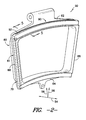
- the aft frame 50 of the present disclosure may define a cooling slot 90 or a plurality of cooling slots 90.
- the cooling slots 90 may extend generally about a portion of the periphery 61.
- a cooling slot 90 may be defined in the upper portion 62 and/or the lower portion 64.
- the cooling slots 90 may extend generally about only a portion of the periphery 61.
- a cooling slot 90 may extend through only a portion of the upper portion 62 and/or the lower portion 64.
- the cooling slots 90 may be defined in the aft frame 50 during casting of the aft frame 50, or may be machined into the aft frame 50 after casting, or may be formed in the aft frame 50 using any other suitable process or device.
- a cooling slot 90 may include an opening 92.
- the opening 92 may be configured to accept coolant 52.
- the opening 92 may be open and exposed to the external annulus 38, such that a portion of the coolant 52 flowing through the external annulus 38 may flow through the opening 92 into the cooling slot 90.
- the opening 92 may be in communication with an independent source such that the coolant 52 may be flowed from the independent source into the cooling slot 90.
- the aft frame 50 may further defme a sealing slot 110 or a plurality of sealing slots 110.
- the sealing slots 110 may extend generally about a portion of periphery 61 or the entire periphery 61 of the body 60. Further, the sealing slots 110 may be configured to receive seals 112 therein.
- the sealing slots 110 may defme openings 114, which may accept seals 112 therein.
- the seals 112 may be provided to prevent leakage and mixing of hot gas and coolant 52. Further, as shown, the seals 112 may provide a generally sealed interface between the aft frame 50 and a retaining ring 116 of the turbine section 18.
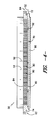
- the cooling slots 90 may be defmed upstream of the sealing slots 110. In other embodiments as shown in FIGS. 5 and 6 , however, the cooling slots 90 may be defmed downstream of the sealing slots 110. It should be noted that “upstream” and “downstream”, for purposes of this disclosure, are defined with respect to the hot gas flow through the combustor 16. If the cooling slots 90 are defmed downstream of the sealing slots 110, the seals 112 may extend across the openings 92 or portions thereof. Thus, in some embodiments, access holes 118 may be defined in the seals 112. These access holes 118 may allow for the flow of coolant 52 therethrough, such that the coolant 52 may be accepted through the openings 92 into the cooling slots 90.
- the access holes 118 may increase the cooling of the aft frame 50, by causing the coolant 52 flowing therethrough to impinge on the aft frame 50 after flowing through cooling slots 90, thus causing impingement cooling of the aft frame 50.
- the present disclosure is further directed to a method for cooling an aft frame 50.
- the method may include, for example, flowing a coolant 52 through a generally radially extending cooling passage 70 defined in the aft frame 50, as discussed above.
- the method may further include, for example, flowing the coolant 52 from the cooling passage 70 into an exhaust passage 80 in communication with the cooling passage 70, as discussed above.
- the method may include, for example, exhausting the coolant 52 from the exhaust passage 80 into a flow path 36, as discussed above.
Landscapes
- Engineering & Computer Science (AREA)
- Mechanical Engineering (AREA)
- General Engineering & Computer Science (AREA)
- Turbine Rotor Nozzle Sealing (AREA)
Applications Claiming Priority (1)
| Application Number | Priority Date | Filing Date | Title |
|---|---|---|---|
| US13/049,237 US9255484B2 (en) | 2011-03-16 | 2011-03-16 | Aft frame and method for cooling aft frame |
Publications (3)
| Publication Number | Publication Date |
|---|---|
| EP2500523A2 true EP2500523A2 (fr) | 2012-09-19 |
| EP2500523A3 EP2500523A3 (fr) | 2017-06-14 |
| EP2500523B1 EP2500523B1 (fr) | 2019-06-12 |
Family
ID=45808271
Family Applications (1)
| Application Number | Title | Priority Date | Filing Date |
|---|---|---|---|
| EP12158160.7A Active EP2500523B1 (fr) | 2011-03-16 | 2012-03-06 | Cadre arrière et procédé de refroidissement du cadre |
Country Status (3)
| Country | Link |
|---|---|
| US (1) | US9255484B2 (fr) |
| EP (1) | EP2500523B1 (fr) |
| CN (1) | CN102679402B (fr) |
Cited By (4)
| Publication number | Priority date | Publication date | Assignee | Title |
|---|---|---|---|---|
| EP2589756A3 (fr) * | 2011-11-07 | 2013-12-25 | General Electric Company | Ossature arrière de pièce de transition |
| EP3026219A1 (fr) * | 2014-11-27 | 2016-06-01 | Alstom Technology Ltd | Segment de support d'une pièce de transition de chambre de combustion d'une turbine |
| EP3470628A1 (fr) * | 2017-10-13 | 2019-04-17 | General Electric Company | Ensemble de cadre arrière pour pièce de transition d'une turbine à gaz |
| EP3473812A1 (fr) * | 2017-10-13 | 2019-04-24 | General Electric Company | Ensemble de cadre arrière pour pièce de transition d'une turbine à gaz |
Families Citing this family (17)
| Publication number | Priority date | Publication date | Assignee | Title |
|---|---|---|---|---|
| US9115585B2 (en) * | 2011-06-06 | 2015-08-25 | General Electric Company | Seal assembly for gas turbine |
| JP5804872B2 (ja) * | 2011-09-27 | 2015-11-04 | 三菱日立パワーシステムズ株式会社 | 燃焼器の尾筒、これを備えているガスタービン、及び尾筒の製造方法 |
| US20140000267A1 (en) * | 2012-06-29 | 2014-01-02 | General Electric Company | Transition duct for a gas turbine |
| US20150121884A1 (en) * | 2013-02-15 | 2015-05-07 | United Technologies Corporation | Stress relieved rectilinear duct |
| US9574498B2 (en) * | 2013-09-25 | 2017-02-21 | General Electric Company | Internally cooled transition duct aft frame with serpentine cooling passage and conduit |
| US9909432B2 (en) * | 2013-11-26 | 2018-03-06 | General Electric Company | Gas turbine transition piece aft frame assemblies with cooling channels and methods for manufacturing the same |
| EP2907977A1 (fr) * | 2014-02-14 | 2015-08-19 | Siemens Aktiengesellschaft | Composant pouvant être alimenté par un gaz chaud pour une turbine à gaz et système d'étanchéité doté d'un tel composant |
| US10156157B2 (en) * | 2015-02-13 | 2018-12-18 | United Technologies Corporation | S-shaped trip strips in internally cooled components |
| EP3124749B1 (fr) * | 2015-07-28 | 2018-12-19 | Ansaldo Energia Switzerland AG | Dispositif d'aube de turbine de premièr ètage |
| US10782025B2 (en) * | 2015-09-15 | 2020-09-22 | Mitsubishi Hitachi Power Systems, Ltd. | Combustor pipe, combustor, and gas turbine |
| EP3287610B1 (fr) * | 2016-08-22 | 2019-07-10 | Ansaldo Energia Switzerland AG | Conduit de transition de turbine à gaz |
| US10830142B2 (en) * | 2016-10-10 | 2020-11-10 | General Electric Company | Combustor aft frame cooling |
| EP3421726B1 (fr) * | 2017-06-30 | 2020-12-30 | Ansaldo Energia Switzerland AG | Cadre d'image de connexion d'une chambre de combustion à une turbine dans une turbine à gaz et turbine à gaz comprenant un cadre d'image |
| US10718224B2 (en) * | 2017-10-13 | 2020-07-21 | General Electric Company | AFT frame assembly for gas turbine transition piece |
| US11215072B2 (en) * | 2017-10-13 | 2022-01-04 | General Electric Company | Aft frame assembly for gas turbine transition piece |
| JP7175298B2 (ja) * | 2020-07-27 | 2022-11-18 | 三菱重工業株式会社 | ガスタービン燃焼器 |
| US11187152B1 (en) * | 2020-09-30 | 2021-11-30 | General Electric Company | Turbomachine sealing arrangement having a cooling flow director |
Family Cites Families (37)
| Publication number | Priority date | Publication date | Assignee | Title |
|---|---|---|---|---|
| US4195474A (en) * | 1977-10-17 | 1980-04-01 | General Electric Company | Liquid-cooled transition member to turbine inlet |
| JPS5554636A (en) | 1978-10-16 | 1980-04-22 | Hitachi Ltd | Combustor of gas turbine |
| US4465284A (en) * | 1983-09-19 | 1984-08-14 | General Electric Company | Scalloped cooling of gas turbine transition piece frame |
| US5265412A (en) * | 1992-07-28 | 1993-11-30 | General Electric Company | Self-accommodating brush seal for gas turbine combustor |
| US5474306A (en) * | 1992-11-19 | 1995-12-12 | General Electric Co. | Woven seal and hybrid cloth-brush seals for turbine applications |
| US5414999A (en) | 1993-11-05 | 1995-05-16 | General Electric Company | Integral aft frame mount for a gas turbine combustor transition piece |
| US5749218A (en) * | 1993-12-17 | 1998-05-12 | General Electric Co. | Wear reduction kit for gas turbine combustors |
| JP4031590B2 (ja) * | 1999-03-08 | 2008-01-09 | 三菱重工業株式会社 | 燃焼器の尾筒シール構造及びその構造を用いたガスタービン |
| US6412268B1 (en) * | 2000-04-06 | 2002-07-02 | General Electric Company | Cooling air recycling for gas turbine transition duct end frame and related method |
| DE60137099D1 (de) * | 2000-04-13 | 2009-02-05 | Mitsubishi Heavy Ind Ltd | Kühlstruktur für das Endstück einer Gasturbinenbrennkammer |
| JP2002243154A (ja) | 2001-02-16 | 2002-08-28 | Mitsubishi Heavy Ind Ltd | ガスタービン燃焼器尾筒出口構造及びガスタービン燃焼器 |
| JP3600912B2 (ja) * | 2001-09-12 | 2004-12-15 | 川崎重工業株式会社 | 燃焼器ライナのシール構造 |
| FR2840974B1 (fr) * | 2002-06-13 | 2005-12-30 | Snecma Propulsion Solide | Anneau d'etancheite pour cahmbre de combustion et chambre de combustion comportant un tel anneau |
| DE10233805B4 (de) * | 2002-07-25 | 2013-08-22 | Alstom Technology Ltd. | Ringförmige Brennkammer für eine Gasturbine |
| US6834507B2 (en) * | 2002-08-15 | 2004-12-28 | Power Systems Mfg., Llc | Convoluted seal with enhanced wear capability |
| US6792763B2 (en) * | 2002-08-15 | 2004-09-21 | Power Systems Mfg., Llc | Coated seal article with multiple coatings |
| US6860108B2 (en) * | 2003-01-22 | 2005-03-01 | Mitsubishi Heavy Industries, Ltd. | Gas turbine tail tube seal and gas turbine using the same |
| JP4191552B2 (ja) | 2003-07-14 | 2008-12-03 | 三菱重工業株式会社 | ガスタービン尾筒の冷却構造 |
| US7043921B2 (en) * | 2003-08-26 | 2006-05-16 | Honeywell International, Inc. | Tube cooled combustor |
| US8015818B2 (en) * | 2005-02-22 | 2011-09-13 | Siemens Energy, Inc. | Cooled transition duct for a gas turbine engine |
| JP4476152B2 (ja) * | 2005-04-01 | 2010-06-09 | 三菱重工業株式会社 | ガスタービン燃焼器 |
| EP1724526A1 (fr) * | 2005-05-13 | 2006-11-22 | Siemens Aktiengesellschaft | Coquille de turbine à gaz, turbine à gaz et procédé de démarrage et d'arrêt d'une turbine à gaz |
| US7377117B2 (en) * | 2005-08-09 | 2008-05-27 | Turbine Services, Ltd. | Transition piece for gas turbine |
| US7784264B2 (en) * | 2006-08-03 | 2010-08-31 | Siemens Energy, Inc. | Slidable spring-loaded transition-to-turbine seal apparatus and heat-shielding system, comprising the seal, at transition/turbine junction of a gas turbine engine |
| US8001787B2 (en) * | 2007-02-27 | 2011-08-23 | Siemens Energy, Inc. | Transition support system for combustion transition ducts for turbine engines |
| US7797948B2 (en) * | 2007-03-27 | 2010-09-21 | Siemens Energy, Inc. | Transition-to-turbine seal apparatus and transition-to-turbine seal junction of a gas turbine engine |
| FR2921463B1 (fr) * | 2007-09-26 | 2013-12-06 | Snecma | Chambre de combustion d'une turbomachine |
| US8322146B2 (en) | 2007-12-10 | 2012-12-04 | Alstom Technology Ltd | Transition duct assembly |
| US20090324387A1 (en) | 2008-06-30 | 2009-12-31 | General Electric Company | Aft frame with oval-shaped cooling slots and related method |
| US8186167B2 (en) | 2008-07-07 | 2012-05-29 | General Electric Company | Combustor transition piece aft end cooling and related method |
| US8245515B2 (en) | 2008-08-06 | 2012-08-21 | General Electric Company | Transition duct aft end frame cooling and related method |
| FR2937098B1 (fr) * | 2008-10-15 | 2015-11-20 | Snecma | Etancheite entre une chambre de combustion et un distributeur de turbine dans une turbomachine |
| US20100205972A1 (en) | 2009-02-17 | 2010-08-19 | General Electric Company | One-piece can combustor with heat transfer surface enhacements |
| US8092159B2 (en) * | 2009-03-31 | 2012-01-10 | General Electric Company | Feeding film cooling holes from seal slots |
| JP5653705B2 (ja) * | 2010-09-30 | 2015-01-14 | 三菱重工業株式会社 | 回収式空気冷却ガスタービン燃焼器冷却構造 |
| US8573938B1 (en) * | 2010-11-22 | 2013-11-05 | Florida Turbine Technologies, Inc. | Turbine vane with endwall film cooling |
| US8353165B2 (en) * | 2011-02-18 | 2013-01-15 | General Electric Company | Combustor assembly for use in a turbine engine and methods of fabricating same |
-
2011
- 2011-03-16 US US13/049,237 patent/US9255484B2/en active Active
-
2012
- 2012-03-06 EP EP12158160.7A patent/EP2500523B1/fr active Active
- 2012-03-15 CN CN201210078945.6A patent/CN102679402B/zh active Active
Non-Patent Citations (1)
| Title |
|---|
| None |
Cited By (7)
| Publication number | Priority date | Publication date | Assignee | Title |
|---|---|---|---|---|
| EP2589756A3 (fr) * | 2011-11-07 | 2013-12-25 | General Electric Company | Ossature arrière de pièce de transition |
| US9127552B2 (en) | 2011-11-07 | 2015-09-08 | General Electric Company | Transition piece aft frame with fuel injection apertures |
| EP3026219A1 (fr) * | 2014-11-27 | 2016-06-01 | Alstom Technology Ltd | Segment de support d'une pièce de transition de chambre de combustion d'une turbine |
| US10072515B2 (en) | 2014-11-27 | 2018-09-11 | Ansaldo Energia Switzerland AG | Frame segment for a combustor turbine interface |
| EP3470628A1 (fr) * | 2017-10-13 | 2019-04-17 | General Electric Company | Ensemble de cadre arrière pour pièce de transition d'une turbine à gaz |
| EP3473812A1 (fr) * | 2017-10-13 | 2019-04-24 | General Electric Company | Ensemble de cadre arrière pour pièce de transition d'une turbine à gaz |
| US10684016B2 (en) | 2017-10-13 | 2020-06-16 | General Electric Company | Aft frame assembly for gas turbine transition piece |
Also Published As
| Publication number | Publication date |
|---|---|
| EP2500523B1 (fr) | 2019-06-12 |
| US20120234018A1 (en) | 2012-09-20 |
| CN102679402B (zh) | 2015-11-25 |
| US9255484B2 (en) | 2016-02-09 |
| CN102679402A (zh) | 2012-09-19 |
| EP2500523A3 (fr) | 2017-06-14 |
Similar Documents
| Publication | Publication Date | Title |
|---|---|---|
| US9255484B2 (en) | Aft frame and method for cooling aft frame | |
| US9080447B2 (en) | Transition duct with divided upstream and downstream portions | |
| JP6176723B2 (ja) | 燃焼器キャップアセンブリ | |
| JP5391225B2 (ja) | トランジションダクト界面における燃焼器ライナ冷却及びその関連する方法 | |
| CN103032894B (zh) | 用于供应加压流体至燃气轮机燃烧器的帽盖组件的系统 | |
| EP3214373B1 (fr) | Injecteur de carburant à faisceau tubulaire avec refroidissement interne | |
| US8959886B2 (en) | Mesh cooled conduit for conveying combustion gases | |
| US8701415B2 (en) | Flexible metallic seal for transition duct in turbine system | |
| EP2592232A2 (fr) | Joint plat pour conduit de transition dans un système de turbine | |
| CN107796015B (zh) | 束管燃料喷嘴组件、燃烧器以及燃气涡轮机 | |
| EP2484978A2 (fr) | Procédé et appareil de refroidissement de chemise de chambre de combustion dans une chambre à combustion | |
| CN101514658A (zh) | 紊流的后端衬里组件及冷却方法 | |
| CZ20022075A3 (cs) | Způsob a zařízení pro chlazení spalovacích komor soustrojí plynové turbíny | |
| JP2001289062A (ja) | ガスタービン燃焼器の壁面冷却構造 | |
| CA2936200C (fr) | Systeme de refroidissement de chambre de combustion | |
| CN1576698B (zh) | 用于操作燃气涡轮发动机燃烧室的方法和装置 | |
| US20120031099A1 (en) | Combustor assembly for use in a turbine engine and methods of assembling same | |
| US10648667B2 (en) | Combustion chamber with double wall | |
| CN103104348B (zh) | 用于涡轮系统中的过渡管的折合式密封件 | |
| US8813501B2 (en) | Combustor assemblies for use in turbine engines and methods of assembling same | |
| JP2014148964A (ja) | ガスタービン尾筒シール及びガスタービン |
Legal Events
| Date | Code | Title | Description |
|---|---|---|---|
| PUAI | Public reference made under article 153(3) epc to a published international application that has entered the european phase |
Free format text: ORIGINAL CODE: 0009012 |
|
| AK | Designated contracting states |
Kind code of ref document: A2 Designated state(s): AL AT BE BG CH CY CZ DE DK EE ES FI FR GB GR HR HU IE IS IT LI LT LU LV MC MK MT NL NO PL PT RO RS SE SI SK SM TR |
|
| AX | Request for extension of the european patent |
Extension state: BA ME |
|
| PUAL | Search report despatched |
Free format text: ORIGINAL CODE: 0009013 |
|
| AK | Designated contracting states |
Kind code of ref document: A3 Designated state(s): AL AT BE BG CH CY CZ DE DK EE ES FI FR GB GR HR HU IE IS IT LI LT LU LV MC MK MT NL NO PL PT RO RS SE SI SK SM TR |
|
| AX | Request for extension of the european patent |
Extension state: BA ME |
|
| RIC1 | Information provided on ipc code assigned before grant |
Ipc: F01D 9/02 20060101AFI20170511BHEP Ipc: F01D 25/12 20060101ALI20170511BHEP Ipc: F23R 3/60 20060101ALI20170511BHEP Ipc: F01D 25/14 20060101ALI20170511BHEP Ipc: F02C 7/20 20060101ALI20170511BHEP |
|
| STAA | Information on the status of an ep patent application or granted ep patent |
Free format text: STATUS: REQUEST FOR EXAMINATION WAS MADE |
|
| 17P | Request for examination filed |
Effective date: 20171214 |
|
| RBV | Designated contracting states (corrected) |
Designated state(s): AL AT BE BG CH CY CZ DE DK EE ES FI FR GB GR HR HU IE IS IT LI LT LU LV MC MK MT NL NO PL PT RO RS SE SI SK SM TR |
|
| STAA | Information on the status of an ep patent application or granted ep patent |
Free format text: STATUS: EXAMINATION IS IN PROGRESS |
|
| 17Q | First examination report despatched |
Effective date: 20180703 |
|
| GRAP | Despatch of communication of intention to grant a patent |
Free format text: ORIGINAL CODE: EPIDOSNIGR1 |
|
| STAA | Information on the status of an ep patent application or granted ep patent |
Free format text: STATUS: GRANT OF PATENT IS INTENDED |
|
| INTG | Intention to grant announced |
Effective date: 20190114 |
|
| GRAS | Grant fee paid |
Free format text: ORIGINAL CODE: EPIDOSNIGR3 |
|
| GRAA | (expected) grant |
Free format text: ORIGINAL CODE: 0009210 |
|
| STAA | Information on the status of an ep patent application or granted ep patent |
Free format text: STATUS: THE PATENT HAS BEEN GRANTED |
|
| AK | Designated contracting states |
Kind code of ref document: B1 Designated state(s): AL AT BE BG CH CY CZ DE DK EE ES FI FR GB GR HR HU IE IS IT LI LT LU LV MC MK MT NL NO PL PT RO RS SE SI SK SM TR |
|
| REG | Reference to a national code |
Ref country code: GB Ref legal event code: FG4D |
|
| REG | Reference to a national code |
Ref country code: CH Ref legal event code: EP |
|
| REG | Reference to a national code |
Ref country code: AT Ref legal event code: REF Ref document number: 1142792 Country of ref document: AT Kind code of ref document: T Effective date: 20190615 |
|
| REG | Reference to a national code |
Ref country code: DE Ref legal event code: R096 Ref document number: 602012060838 Country of ref document: DE |
|
| REG | Reference to a national code |
Ref country code: IE Ref legal event code: FG4D |
|
| REG | Reference to a national code |
Ref country code: NL Ref legal event code: MP Effective date: 20190612 |
|
| REG | Reference to a national code |
Ref country code: LT Ref legal event code: MG4D |
|
| PG25 | Lapsed in a contracting state [announced via postgrant information from national office to epo] |
Ref country code: NO Free format text: LAPSE BECAUSE OF FAILURE TO SUBMIT A TRANSLATION OF THE DESCRIPTION OR TO PAY THE FEE WITHIN THE PRESCRIBED TIME-LIMIT Effective date: 20190912 Ref country code: ES Free format text: LAPSE BECAUSE OF FAILURE TO SUBMIT A TRANSLATION OF THE DESCRIPTION OR TO PAY THE FEE WITHIN THE PRESCRIBED TIME-LIMIT Effective date: 20190612 Ref country code: LT Free format text: LAPSE BECAUSE OF FAILURE TO SUBMIT A TRANSLATION OF THE DESCRIPTION OR TO PAY THE FEE WITHIN THE PRESCRIBED TIME-LIMIT Effective date: 20190612 Ref country code: SE Free format text: LAPSE BECAUSE OF FAILURE TO SUBMIT A TRANSLATION OF THE DESCRIPTION OR TO PAY THE FEE WITHIN THE PRESCRIBED TIME-LIMIT Effective date: 20190612 Ref country code: HR Free format text: LAPSE BECAUSE OF FAILURE TO SUBMIT A TRANSLATION OF THE DESCRIPTION OR TO PAY THE FEE WITHIN THE PRESCRIBED TIME-LIMIT Effective date: 20190612 Ref country code: AL Free format text: LAPSE BECAUSE OF FAILURE TO SUBMIT A TRANSLATION OF THE DESCRIPTION OR TO PAY THE FEE WITHIN THE PRESCRIBED TIME-LIMIT Effective date: 20190612 Ref country code: FI Free format text: LAPSE BECAUSE OF FAILURE TO SUBMIT A TRANSLATION OF THE DESCRIPTION OR TO PAY THE FEE WITHIN THE PRESCRIBED TIME-LIMIT Effective date: 20190612 |
|
| PG25 | Lapsed in a contracting state [announced via postgrant information from national office to epo] |
Ref country code: LV Free format text: LAPSE BECAUSE OF FAILURE TO SUBMIT A TRANSLATION OF THE DESCRIPTION OR TO PAY THE FEE WITHIN THE PRESCRIBED TIME-LIMIT Effective date: 20190612 Ref country code: GR Free format text: LAPSE BECAUSE OF FAILURE TO SUBMIT A TRANSLATION OF THE DESCRIPTION OR TO PAY THE FEE WITHIN THE PRESCRIBED TIME-LIMIT Effective date: 20190913 Ref country code: RS Free format text: LAPSE BECAUSE OF FAILURE TO SUBMIT A TRANSLATION OF THE DESCRIPTION OR TO PAY THE FEE WITHIN THE PRESCRIBED TIME-LIMIT Effective date: 20190612 Ref country code: BG Free format text: LAPSE BECAUSE OF FAILURE TO SUBMIT A TRANSLATION OF THE DESCRIPTION OR TO PAY THE FEE WITHIN THE PRESCRIBED TIME-LIMIT Effective date: 20190912 |
|
| REG | Reference to a national code |
Ref country code: AT Ref legal event code: MK05 Ref document number: 1142792 Country of ref document: AT Kind code of ref document: T Effective date: 20190612 |
|
| PG25 | Lapsed in a contracting state [announced via postgrant information from national office to epo] |
Ref country code: CZ Free format text: LAPSE BECAUSE OF FAILURE TO SUBMIT A TRANSLATION OF THE DESCRIPTION OR TO PAY THE FEE WITHIN THE PRESCRIBED TIME-LIMIT Effective date: 20190612 Ref country code: RO Free format text: LAPSE BECAUSE OF FAILURE TO SUBMIT A TRANSLATION OF THE DESCRIPTION OR TO PAY THE FEE WITHIN THE PRESCRIBED TIME-LIMIT Effective date: 20190612 Ref country code: SK Free format text: LAPSE BECAUSE OF FAILURE TO SUBMIT A TRANSLATION OF THE DESCRIPTION OR TO PAY THE FEE WITHIN THE PRESCRIBED TIME-LIMIT Effective date: 20190612 Ref country code: PT Free format text: LAPSE BECAUSE OF FAILURE TO SUBMIT A TRANSLATION OF THE DESCRIPTION OR TO PAY THE FEE WITHIN THE PRESCRIBED TIME-LIMIT Effective date: 20191014 Ref country code: NL Free format text: LAPSE BECAUSE OF FAILURE TO SUBMIT A TRANSLATION OF THE DESCRIPTION OR TO PAY THE FEE WITHIN THE PRESCRIBED TIME-LIMIT Effective date: 20190612 Ref country code: EE Free format text: LAPSE BECAUSE OF FAILURE TO SUBMIT A TRANSLATION OF THE DESCRIPTION OR TO PAY THE FEE WITHIN THE PRESCRIBED TIME-LIMIT Effective date: 20190612 Ref country code: AT Free format text: LAPSE BECAUSE OF FAILURE TO SUBMIT A TRANSLATION OF THE DESCRIPTION OR TO PAY THE FEE WITHIN THE PRESCRIBED TIME-LIMIT Effective date: 20190612 |
|
| PG25 | Lapsed in a contracting state [announced via postgrant information from national office to epo] |
Ref country code: IT Free format text: LAPSE BECAUSE OF FAILURE TO SUBMIT A TRANSLATION OF THE DESCRIPTION OR TO PAY THE FEE WITHIN THE PRESCRIBED TIME-LIMIT Effective date: 20190612 Ref country code: IS Free format text: LAPSE BECAUSE OF FAILURE TO SUBMIT A TRANSLATION OF THE DESCRIPTION OR TO PAY THE FEE WITHIN THE PRESCRIBED TIME-LIMIT Effective date: 20191012 Ref country code: SM Free format text: LAPSE BECAUSE OF FAILURE TO SUBMIT A TRANSLATION OF THE DESCRIPTION OR TO PAY THE FEE WITHIN THE PRESCRIBED TIME-LIMIT Effective date: 20190612 |
|
| REG | Reference to a national code |
Ref country code: DE Ref legal event code: R097 Ref document number: 602012060838 Country of ref document: DE |
|
| PG25 | Lapsed in a contracting state [announced via postgrant information from national office to epo] |
Ref country code: TR Free format text: LAPSE BECAUSE OF FAILURE TO SUBMIT A TRANSLATION OF THE DESCRIPTION OR TO PAY THE FEE WITHIN THE PRESCRIBED TIME-LIMIT Effective date: 20190612 |
|
| PLBE | No opposition filed within time limit |
Free format text: ORIGINAL CODE: 0009261 |
|
| STAA | Information on the status of an ep patent application or granted ep patent |
Free format text: STATUS: NO OPPOSITION FILED WITHIN TIME LIMIT |
|
| PG25 | Lapsed in a contracting state [announced via postgrant information from national office to epo] |
Ref country code: DK Free format text: LAPSE BECAUSE OF FAILURE TO SUBMIT A TRANSLATION OF THE DESCRIPTION OR TO PAY THE FEE WITHIN THE PRESCRIBED TIME-LIMIT Effective date: 20190612 Ref country code: PL Free format text: LAPSE BECAUSE OF FAILURE TO SUBMIT A TRANSLATION OF THE DESCRIPTION OR TO PAY THE FEE WITHIN THE PRESCRIBED TIME-LIMIT Effective date: 20190612 |
|
| 26N | No opposition filed |
Effective date: 20200313 |
|
| PG25 | Lapsed in a contracting state [announced via postgrant information from national office to epo] |
Ref country code: IS Free format text: LAPSE BECAUSE OF FAILURE TO SUBMIT A TRANSLATION OF THE DESCRIPTION OR TO PAY THE FEE WITHIN THE PRESCRIBED TIME-LIMIT Effective date: 20200224 Ref country code: SI Free format text: LAPSE BECAUSE OF FAILURE TO SUBMIT A TRANSLATION OF THE DESCRIPTION OR TO PAY THE FEE WITHIN THE PRESCRIBED TIME-LIMIT Effective date: 20190612 |
|
| PG2D | Information on lapse in contracting state deleted |
Ref country code: IS |
|
| PG25 | Lapsed in a contracting state [announced via postgrant information from national office to epo] |
Ref country code: MC Free format text: LAPSE BECAUSE OF FAILURE TO SUBMIT A TRANSLATION OF THE DESCRIPTION OR TO PAY THE FEE WITHIN THE PRESCRIBED TIME-LIMIT Effective date: 20190612 |
|
| REG | Reference to a national code |
Ref country code: CH Ref legal event code: PL |
|
| REG | Reference to a national code |
Ref country code: BE Ref legal event code: MM Effective date: 20200331 |
|
| PG25 | Lapsed in a contracting state [announced via postgrant information from national office to epo] |
Ref country code: LU Free format text: LAPSE BECAUSE OF NON-PAYMENT OF DUE FEES Effective date: 20200306 |
|
| PG25 | Lapsed in a contracting state [announced via postgrant information from national office to epo] |
Ref country code: IE Free format text: LAPSE BECAUSE OF NON-PAYMENT OF DUE FEES Effective date: 20200306 Ref country code: CH Free format text: LAPSE BECAUSE OF NON-PAYMENT OF DUE FEES Effective date: 20200331 Ref country code: LI Free format text: LAPSE BECAUSE OF NON-PAYMENT OF DUE FEES Effective date: 20200331 |
|
| PG25 | Lapsed in a contracting state [announced via postgrant information from national office to epo] |
Ref country code: BE Free format text: LAPSE BECAUSE OF NON-PAYMENT OF DUE FEES Effective date: 20200331 |
|
| GBPC | Gb: european patent ceased through non-payment of renewal fee |
Effective date: 20200306 |
|
| PG25 | Lapsed in a contracting state [announced via postgrant information from national office to epo] |
Ref country code: GB Free format text: LAPSE BECAUSE OF NON-PAYMENT OF DUE FEES Effective date: 20200306 |
|
| PG25 | Lapsed in a contracting state [announced via postgrant information from national office to epo] |
Ref country code: MT Free format text: LAPSE BECAUSE OF FAILURE TO SUBMIT A TRANSLATION OF THE DESCRIPTION OR TO PAY THE FEE WITHIN THE PRESCRIBED TIME-LIMIT Effective date: 20190612 Ref country code: CY Free format text: LAPSE BECAUSE OF FAILURE TO SUBMIT A TRANSLATION OF THE DESCRIPTION OR TO PAY THE FEE WITHIN THE PRESCRIBED TIME-LIMIT Effective date: 20190612 |
|
| PGFP | Annual fee paid to national office [announced via postgrant information from national office to epo] |
Ref country code: FR Payment date: 20220218 Year of fee payment: 11 |
|
| PG25 | Lapsed in a contracting state [announced via postgrant information from national office to epo] |
Ref country code: MK Free format text: LAPSE BECAUSE OF FAILURE TO SUBMIT A TRANSLATION OF THE DESCRIPTION OR TO PAY THE FEE WITHIN THE PRESCRIBED TIME-LIMIT Effective date: 20190612 |
|
| REG | Reference to a national code |
Ref country code: DE Ref legal event code: R082 Ref document number: 602012060838 Country of ref document: DE Ref country code: DE Ref legal event code: R081 Ref document number: 602012060838 Country of ref document: DE Owner name: GENERAL ELECTRIC TECHNOLOGY GMBH, CH Free format text: FORMER OWNER: GENERAL ELECTRIC COMPANY, SCHENECTADY, NY, US |
|
| PG25 | Lapsed in a contracting state [announced via postgrant information from national office to epo] |
Ref country code: FR Free format text: LAPSE BECAUSE OF NON-PAYMENT OF DUE FEES Effective date: 20230331 |
|
| PGFP | Annual fee paid to national office [announced via postgrant information from national office to epo] |
Ref country code: DE Payment date: 20260219 Year of fee payment: 15 |