EP2500525B1 - Tige d'amortissement - Google Patents
Tige d'amortissement Download PDFInfo
- Publication number
- EP2500525B1 EP2500525B1 EP12159603.5A EP12159603A EP2500525B1 EP 2500525 B1 EP2500525 B1 EP 2500525B1 EP 12159603 A EP12159603 A EP 12159603A EP 2500525 B1 EP2500525 B1 EP 2500525B1
- Authority
- EP
- European Patent Office
- Prior art keywords
- pin
- region
- undercut
- main body
- longitudinal end
- Prior art date
- Legal status (The legal status is an assumption and is not a legal conclusion. Google has not performed a legal analysis and makes no representation as to the accuracy of the status listed.)
- Active
Links
Images



Classifications
-
- F—MECHANICAL ENGINEERING; LIGHTING; HEATING; WEAPONS; BLASTING
- F01—MACHINES OR ENGINES IN GENERAL; ENGINE PLANTS IN GENERAL; STEAM ENGINES
- F01D—NON-POSITIVE DISPLACEMENT MACHINES OR ENGINES, e.g. STEAM TURBINES
- F01D5/00—Blades; Blade-carrying members; Heating, heat-insulating, cooling or antivibration means on the blades or the members
- F01D5/12—Blades
- F01D5/22—Blade-to-blade connections, e.g. for damping vibrations
-
- F—MECHANICAL ENGINEERING; LIGHTING; HEATING; WEAPONS; BLASTING
- F01—MACHINES OR ENGINES IN GENERAL; ENGINE PLANTS IN GENERAL; STEAM ENGINES
- F01D—NON-POSITIVE DISPLACEMENT MACHINES OR ENGINES, e.g. STEAM TURBINES
- F01D11/00—Preventing or minimising internal leakage of working-fluid, e.g. between stages
- F01D11/005—Sealing means between non relatively rotating elements
- F01D11/006—Sealing the gap between rotor blades or blades and rotor
-
- F—MECHANICAL ENGINEERING; LIGHTING; HEATING; WEAPONS; BLASTING
- F01—MACHINES OR ENGINES IN GENERAL; ENGINE PLANTS IN GENERAL; STEAM ENGINES
- F01D—NON-POSITIVE DISPLACEMENT MACHINES OR ENGINES, e.g. STEAM TURBINES
- F01D11/00—Preventing or minimising internal leakage of working-fluid, e.g. between stages
- F01D11/005—Sealing means between non relatively rotating elements
- F01D11/006—Sealing the gap between rotor blades or blades and rotor
- F01D11/008—Sealing the gap between rotor blades or blades and rotor by spacer elements between the blades, e.g. independent interblade platforms
-
- F—MECHANICAL ENGINEERING; LIGHTING; HEATING; WEAPONS; BLASTING
- F05—INDEXING SCHEMES RELATING TO ENGINES OR PUMPS IN VARIOUS SUBCLASSES OF CLASSES F01-F04
- F05D—INDEXING SCHEME FOR ASPECTS RELATING TO NON-POSITIVE-DISPLACEMENT MACHINES OR ENGINES, GAS-TURBINES OR JET-PROPULSION PLANTS
- F05D2250/00—Geometry
- F05D2250/20—Three-dimensional
- F05D2250/25—Three-dimensional helical
-
- Y—GENERAL TAGGING OF NEW TECHNOLOGICAL DEVELOPMENTS; GENERAL TAGGING OF CROSS-SECTIONAL TECHNOLOGIES SPANNING OVER SEVERAL SECTIONS OF THE IPC; TECHNICAL SUBJECTS COVERED BY FORMER USPC CROSS-REFERENCE ART COLLECTIONS [XRACs] AND DIGESTS
- Y10—TECHNICAL SUBJECTS COVERED BY FORMER USPC
- Y10S—TECHNICAL SUBJECTS COVERED BY FORMER USPC CROSS-REFERENCE ART COLLECTIONS [XRACs] AND DIGESTS
- Y10S416/00—Fluid reaction surfaces, i.e. impellers
- Y10S416/50—Vibration damping features
Definitions
- the present invention relates to the field of damper pins for turbine blades of gas turbine engines, and in particular to a damper pin separating platforms of adjacent turbine blades while allowing cooling air flow to the mate face of the adjacent blades.
- Turbine blades generally include an airfoil, a platform, a shank and a dovetail that engages a rotor disk.
- An axially extending damper pin couples adjacent turbine blades along their platforms.
- a scallop cut may be provided in the platform rail.
- a prior art pin having the features of the preamble of claim 1, is shown in US-4088421 .
- Prior art pins are also shown in EP-1452692 and EP-2110515 .
- the first and second main body regions may be cylindrical.
- the undercut region may also be cylindrical.
- the mate faces of the adjacent turbine blades are cooled by air passing through the pin in one embodiment, and around diameter reduction areas in other embodiments.
- the pin may also include positioning mistake proof features on one of its longitudinal end regions.
- FIG. 1 is a pictorial illustration of adjacent gas turbine blades 10, 12 coupled by a damper pin 14.
- Each of the blades 10, 12 extends radially outward from a rotor disk (not shown), and includes an airfoil 16, 18, a platform 20, 22, a shank 24, 26, and a dovetail 28, 30, respectively.
- the airfoil, platform, shank, and dovetail are collectively known as a bucket.
- FIG. 2 is an exploded view of the pin 14 coupling the adjacent turbine blades 10, 12.
- FIG. 3 is a perspective view of the platform region 22 of the turbine blade 12.
- the airfoil 18 includes a convex suction side 32 and an opposite concave pressure side (not shown), and a leading edge 34 and a trailing edge 36.
- the platform 22 separates the airfoil 18 and the shank 26, and includes an upstream side 38 and a downstream side 40 that are connected together with a suction-side edge 42 and an opposite pressure-side edge (not shown).
- the shank 36 includes a substantially convex sidewall 44 and an opposite substantially concave sidewall (not shown) connected together at an upstream sidewall 46 and a downstream sidewall 48 of the shank 26.
- the substantially convex sidewall 44 of the blade 12 and the substantially concave sidewall of the blade 10 form a shank cavity 50 between the adjacent shanks 24, 26.
- a platform undercut 52 is defined within the platform 22 for trailing edge cooling.
- a first channel 54 and a second channel 56 extend (e.g., axially) from the platform for receiving the damper pin 14 ( FIGs. 1 and 2 ).
- the first channel 54 includes a first pedestal surface 58 on the upstream side
- the second channel 56 includes a second pedestal surface 60 on the downstream side.
- a notch 62 is located on the upstream side of the first pedestal surface 58.
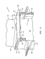
- FIG. 4 is a perspective view of the platform region of the turbine blade 12 with the pin 14 in its operable position within the first and second channels 54, 56.
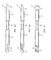
- FIGs. 5A-5C illustrate a first embodiment of the damper pin 14 in various axially rotated views.
- the damper pin includes a first flat longitudinal end region 64, a second flat longitudinal end region 66 and a reduced cross sectional area/undercut region 68.
- the reduced cross sectional area/undercut region 68 is separated from the first flat longitudinal end region 64 by a first main body region 70, and separated from the second flat longitudinal end region 66 by a second main body region 72.
- the cross section of the reduced cross sectional area/undercut region 68 is less than the cross sectional area of each of the first and second main body regions 70, 72.
- the cross sectional area/undercut region 68 is coaxial/concentric with respect to both the first and second main regions 70, 72, and the cooling air flows from the shank cavity 50 along opposite sides of the reduced cross sectional area/undercut region at the same axial position along the pin.
- the first and second longitudinal end regions may have a semi-circular cross section.
- the pin 14 includes a projection 74 at the longitudinal end of the first flat longitudinal end region 64.
- the projection 74 seats in the notch 62 (see FIG. 4 ).
- the pin 14 may be a metal alloy such as for example IN100, IN718, IN625 or INCONEL ® X-750 alloys.
- the depths and width of the reduced cross sectional area 68 of the pin are selected based upon the desired amount of cooling flow to the side edges of the platform (e.g., side edge 42 of the platform 22).
- the reduced cross sectional area may have a diameter of about 0.200 inches (5.08 mm), while the first and second main body regions 70, 72 may have a diameter of about 0.310 inches (7.87 mm).
- the length of the pin 14 is selected to run from about the upstream sidewall to about the downstream sidewall.
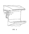
- FIG. 6 illustrates an exploded perspective view of the notch 62.
- the notch is formed by a straight flat surface 67 and an arcuate surface 69 that extends from the flat surface.
- the notch 62 is also formed by notch sidewall surfaces 71, 73.
- the surface 68 may be substantially parallel to the first and second pin channels 54, 56 ( FIG. 3 ), while the sidewall surface 73 may be substantially perpendicular to the damper channels 54, 56.
- the notch 62 may be formed by machining during manufacture of the bucket, or during overhaul or repair of the bucket.
- FIGs. 7A-7C illustrate a second embodiment of a damper pin 70 in various axially rotated views.
- the pin 75 is substantially similar to the pin 14; the two differ primarily in that the undercut region which allows cooling air to pass is formed by a continuous helical cut/channel 80 along the surface of the pin 14 within a helical undercut region 82.
- the helical undercut region 82 is separated from the first flat longitudinal end region 64 by the first cylindrical main body region 70, and from the second flat longitudinal end region 66 by the second cylindrical main body region 72.
- the helical cut allows cooling air to flows from the shank cavity 50 along opposite sides of the pin within the helical undercut region 82.
- first and second main body regions may take on shapes other then cylindrical.
- these regions may be rounded surfaces such as ovals or other surfaces, for example having flat faces such as hexagon, diamond and square.
- the first and second main body regions may also take upon the shape of the adjacent platform surfaces to maintain effective air sealing.
Landscapes
- Engineering & Computer Science (AREA)
- Mechanical Engineering (AREA)
- General Engineering & Computer Science (AREA)
- Turbine Rotor Nozzle Sealing (AREA)
Claims (8)
- Tige (14 ; 75) servant à coupler des plateformes (20, 22) d'aubes de turbine adjacentes (10, 12), la tige (14 ; 75) comprenant :une première région d'extrémité longitudinale plane (64) ;une deuxième région d'extrémité longitudinale plane (66) ; etune région entaillée (68 ; 82), la région entaillée (68 ; 82) étant séparée de la première région d'extrémité longitudinale plane (64) par une première région de corps principal (70) et où la région entaillée (68 ; 82) est séparée de la deuxième région d'extrémité longitudinale plane (66) par une deuxième région de corps principal (72), et où la région entaillée (68 ; 82) est entaillée par rapport aux première et deuxième régions de corps principal (70 ; 72), la région entaillée (68) étant une coupe transversale réduite qui a une surface de coupe transversale inférieure à la surface de coupe transversale de chacune des première et deuxième régions de corps principal (70, 72),
caractérisée en ce que :la coupe transversale réduite (68) est concentrique par rapport aux première et deuxième régions de corps principal (70, 72). - Tige selon la revendication 1, où la coupe transversale réduite (68) est formée par une entaille continue pratiquée dans la surface de la coupe transversale réduite (68).
- Tige selon l'une quelconque des revendications 1 ou 2, dans laquelle l'entaille est cylindrique.
- Tige selon la revendication 1, où la région entaillée (82) est formée par une coupe hélicoïdale continue (80) autour de la surface de la région entaillée, qui permet à l'air réfrigérant de s'écouler le long de surfaces opposées de la tige (14).
- Tige selon l'une quelconque des revendications précédentes, comprenant en outre une saillie (74) s'étendant radialement à partir de l'extrémité longitudinale de la première région d'extrémité longitudinale plane (64).
- Tige selon l'une quelconque des revendications précédentes, où les première et deuxième régions de corps principal (70, 72) sont cylindriques.
- Tige selon l'une quelconque des revendications précédentes, où la tige (14 ; 75 ; 90) est formée d'un alliage métallique.
- Tige selon l'une quelconque des revendications précédentes, où la tige (14 ; 75 ; 90) est formée d'un alliage métallique choisi dans l'ensemble constitué d'IN100, d'IN718, d'IN625 et d'INCONEL X-750.
Applications Claiming Priority (1)
| Application Number | Priority Date | Filing Date | Title |
|---|---|---|---|
| US13/048,618 US8876479B2 (en) | 2011-03-15 | 2011-03-15 | Damper pin |
Publications (2)
| Publication Number | Publication Date |
|---|---|
| EP2500525A1 EP2500525A1 (fr) | 2012-09-19 |
| EP2500525B1 true EP2500525B1 (fr) | 2015-03-04 |
Family
ID=45894206
Family Applications (1)
| Application Number | Title | Priority Date | Filing Date |
|---|---|---|---|
| EP12159603.5A Active EP2500525B1 (fr) | 2011-03-15 | 2012-03-15 | Tige d'amortissement |
Country Status (2)
| Country | Link |
|---|---|
| US (2) | US8876479B2 (fr) |
| EP (1) | EP2500525B1 (fr) |
Families Citing this family (20)
| Publication number | Priority date | Publication date | Assignee | Title |
|---|---|---|---|---|
| EP2938832B1 (fr) | 2012-12-28 | 2019-02-06 | United Technologies Corporation | Aube de turbine renforcée avec coin coupé |
| US20140271205A1 (en) * | 2013-03-12 | 2014-09-18 | Solar Turbines Incorporated | Turbine blade pin seal |
| WO2015042260A1 (fr) * | 2013-09-18 | 2015-03-26 | Zep Solar Llc | Réseau photovoltaïque monté à pente faible |
| US9856737B2 (en) * | 2014-03-27 | 2018-01-02 | United Technologies Corporation | Blades and blade dampers for gas turbine engines |
| US10260350B2 (en) * | 2014-09-05 | 2019-04-16 | United Technologies Corporation | Gas turbine engine airfoil structure |
| EP3034798B1 (fr) * | 2014-12-18 | 2018-03-07 | Ansaldo Energia Switzerland AG | Aube de turbine à gaz |
| US9879548B2 (en) * | 2015-05-14 | 2018-01-30 | General Electric Company | Turbine blade damper system having pin with slots |
| US10472975B2 (en) | 2015-09-03 | 2019-11-12 | General Electric Company | Damper pin having elongated bodies for damping adjacent turbine blades |
| US10584597B2 (en) * | 2015-09-03 | 2020-03-10 | General Electric Company | Variable cross-section damper pin for a turbine blade |
| US10443408B2 (en) | 2015-09-03 | 2019-10-15 | General Electric Company | Damper pin for a turbine blade |
| US20170067347A1 (en) * | 2015-09-03 | 2017-03-09 | General Electric Company | Slotted damper pin for a turbine blade |
| US10385701B2 (en) * | 2015-09-03 | 2019-08-20 | General Electric Company | Damper pin for a turbine blade |
| US10066485B2 (en) * | 2015-12-04 | 2018-09-04 | General Electric Company | Turbomachine blade cover plate having radial cooling groove |
| GB201603554D0 (en) * | 2016-03-01 | 2016-04-13 | Rolls Royce Plc | An intercomponent seal for a gas turbine engine |
| US9845690B1 (en) * | 2016-06-03 | 2017-12-19 | General Electric Company | System and method for sealing flow path components with front-loaded seal |
| US10519785B2 (en) * | 2017-02-14 | 2019-12-31 | General Electric Company | Turbine blades having damper pin slot features and methods of fabricating the same |
| EP3438410B1 (fr) | 2017-08-01 | 2021-09-29 | General Electric Company | Système d'étanchéité pour machine rotative |
| JP6985197B2 (ja) * | 2018-03-28 | 2021-12-22 | 三菱重工業株式会社 | 回転機械 |
| JP7815015B2 (ja) * | 2022-04-21 | 2026-02-17 | 三菱重工業株式会社 | ガスタービン動翼及びガスタービン |
| US12546229B1 (en) * | 2024-12-30 | 2026-02-10 | Pratt & Whitney Canada Corp. | Gas turbine engine rotor stage with seal members |
Citations (1)
| Publication number | Priority date | Publication date | Assignee | Title |
|---|---|---|---|---|
| JPH07305602A (ja) * | 1994-05-12 | 1995-11-21 | Mitsubishi Heavy Ind Ltd | ガスタービン動翼プラットホームの冷却装置 |
Family Cites Families (26)
| Publication number | Priority date | Publication date | Assignee | Title |
|---|---|---|---|---|
| DE2514208A1 (de) * | 1975-04-01 | 1976-10-14 | Kraftwerk Union Ag | Gasturbine der scheibenbauart |
| US4088421A (en) | 1976-09-30 | 1978-05-09 | General Electric Company | Coverplate damping arrangement |
| US4218178A (en) * | 1978-03-31 | 1980-08-19 | General Motors Corporation | Turbine vane structure |
| FR2535794A1 (fr) * | 1982-11-08 | 1984-05-11 | Snecma | Dispositif de retenue axiale et radiale d'aubes de soufflante |
| US4834613A (en) * | 1988-02-26 | 1989-05-30 | United Technologies Corporation | Radially constrained variable vane shroud |
| GB2223277B (en) | 1988-09-30 | 1992-08-12 | Rolls Royce Plc | Aerofoil blade damping |
| US5531457A (en) | 1994-12-07 | 1996-07-02 | Pratt & Whitney Canada, Inc. | Gas turbine engine feather seal arrangement |
| US5800124A (en) | 1996-04-12 | 1998-09-01 | United Technologies Corporation | Cooled rotor assembly for a turbine engine |
| US5746578A (en) | 1996-10-11 | 1998-05-05 | General Electric Company | Retention system for bar-type damper of rotor |
| US6155789A (en) | 1999-04-06 | 2000-12-05 | General Electric Company | Gas turbine engine airfoil damper and method for production |
| GB0304329D0 (en) | 2003-02-26 | 2003-04-02 | Rolls Royce Plc | Damper seal |
| US6776583B1 (en) * | 2003-02-27 | 2004-08-17 | General Electric Company | Turbine bucket damper pin |
| US6932575B2 (en) | 2003-10-08 | 2005-08-23 | United Technologies Corporation | Blade damper |
| US7600972B2 (en) | 2003-10-31 | 2009-10-13 | General Electric Company | Methods and apparatus for cooling gas turbine engine rotor assemblies |
| US7147440B2 (en) | 2003-10-31 | 2006-12-12 | General Electric Company | Methods and apparatus for cooling gas turbine engine rotor assemblies |
| US6984112B2 (en) | 2003-10-31 | 2006-01-10 | General Electric Company | Methods and apparatus for cooling gas turbine rotor blades |
| US7189063B2 (en) | 2004-09-02 | 2007-03-13 | General Electric Company | Methods and apparatus for cooling gas turbine engine rotor assemblies |
| US7090466B2 (en) | 2004-09-14 | 2006-08-15 | General Electric Company | Methods and apparatus for assembling gas turbine engine rotor assemblies |
| US7163376B2 (en) | 2004-11-24 | 2007-01-16 | General Electric Company | Controlled leakage pin and vibration damper for active cooling and purge of bucket slash faces |
| JP2006214367A (ja) | 2005-02-04 | 2006-08-17 | Mitsubishi Heavy Ind Ltd | 動翼体 |
| US7413405B2 (en) | 2005-06-14 | 2008-08-19 | General Electric Company | Bipedal damper turbine blade |
| US7270517B2 (en) | 2005-10-06 | 2007-09-18 | Siemens Power Generation, Inc. | Turbine blade with vibration damper |
| US7762780B2 (en) | 2007-01-25 | 2010-07-27 | Siemens Energy, Inc. | Blade assembly in a combustion turbo-machine providing reduced concentration of mechanical stress and a seal between adjacent assemblies |
| US7762781B1 (en) | 2007-03-06 | 2010-07-27 | Florida Turbine Technologies, Inc. | Composite blade and platform assembly |
| GB0806893D0 (en) * | 2008-04-16 | 2008-05-21 | Rolls Royce Plc | A damper |
| US8876478B2 (en) | 2010-11-17 | 2014-11-04 | General Electric Company | Turbine blade combined damper and sealing pin and related method |
-
2011
- 2011-03-15 US US13/048,618 patent/US8876479B2/en active Active
-
2012
- 2012-03-15 EP EP12159603.5A patent/EP2500525B1/fr active Active
-
2013
- 2013-12-30 US US14/143,828 patent/US9243504B2/en active Active
Patent Citations (1)
| Publication number | Priority date | Publication date | Assignee | Title |
|---|---|---|---|---|
| JPH07305602A (ja) * | 1994-05-12 | 1995-11-21 | Mitsubishi Heavy Ind Ltd | ガスタービン動翼プラットホームの冷却装置 |
Also Published As
| Publication number | Publication date |
|---|---|
| US8876479B2 (en) | 2014-11-04 |
| US9243504B2 (en) | 2016-01-26 |
| US20120237348A1 (en) | 2012-09-20 |
| US20140112792A1 (en) | 2014-04-24 |
| EP2500525A1 (fr) | 2012-09-19 |
Similar Documents
| Publication | Publication Date | Title |
|---|---|---|
| EP2500525B1 (fr) | Tige d'amortissement | |
| EP2500524B1 (fr) | Aube rotorique de moteur à turbine à gaz et ensemble associé | |
| US10822957B2 (en) | Fillet optimization for turbine airfoil | |
| EP2809885B1 (fr) | Aube rotative de soufflante et ensemble associé | |
| EP1939399B1 (fr) | Ensemble de turbine à flux axial | |
| EP2154333B1 (fr) | Profilé d'aube et ensemble de turbine associé | |
| EP1939405B1 (fr) | Ensemble de turbine à flux axial | |
| US9556741B2 (en) | Shrouded blade for a gas turbine engine | |
| EP1795704A2 (fr) | Aube creuse de soufflante pour moteur à turbine à gaz, moteur à turbine à gaz ainsi que procédé pour faire une telle aube creuse de soufflante | |
| EP3314093B1 (fr) | Aube de turbine carénée | |
| US10267161B2 (en) | Gas turbine engine with fillet film holes | |
| EP4130430B1 (fr) | Rotor à aubage intégral | |
| EP1605137B1 (fr) | Aube de rotor refroidie | |
| EP2852736B1 (fr) | Etanchéité de surface d'accouplement de profil aérodynamique | |
| EP3090143B1 (fr) | Ensemble de composants dans un moteur à turbine à gaz | |
| US9739159B2 (en) | Method and system for relieving turbine rotor blade dovetail stress | |
| US9739158B2 (en) | Attachment feature of a gas turbine engine blade having a curved profile | |
| WO2016195689A1 (fr) | Système de fixation pour surface portante de turbine | |
| WO2018004766A1 (fr) | Profil et pale pour moteur à turbine et procédé correspondant de circulation d'un liquide de refroidissement | |
| US20140271171A1 (en) | Compressor airfoil |
Legal Events
| Date | Code | Title | Description |
|---|---|---|---|
| PUAI | Public reference made under article 153(3) epc to a published international application that has entered the european phase |
Free format text: ORIGINAL CODE: 0009012 |
|
| AK | Designated contracting states |
Kind code of ref document: A1 Designated state(s): AL AT BE BG CH CY CZ DE DK EE ES FI FR GB GR HR HU IE IS IT LI LT LU LV MC MK MT NL NO PL PT RO RS SE SI SK SM TR |
|
| AX | Request for extension of the european patent |
Extension state: BA ME |
|
| 17P | Request for examination filed |
Effective date: 20130314 |
|
| 17Q | First examination report despatched |
Effective date: 20130626 |
|
| GRAP | Despatch of communication of intention to grant a patent |
Free format text: ORIGINAL CODE: EPIDOSNIGR1 |
|
| INTG | Intention to grant announced |
Effective date: 20141008 |
|
| GRAS | Grant fee paid |
Free format text: ORIGINAL CODE: EPIDOSNIGR3 |
|
| GRAA | (expected) grant |
Free format text: ORIGINAL CODE: 0009210 |
|
| AK | Designated contracting states |
Kind code of ref document: B1 Designated state(s): AL AT BE BG CH CY CZ DE DK EE ES FI FR GB GR HR HU IE IS IT LI LT LU LV MC MK MT NL NO PL PT RO RS SE SI SK SM TR |
|
| REG | Reference to a national code |
Ref country code: GB Ref legal event code: FG4D |
|
| REG | Reference to a national code |
Ref country code: CH Ref legal event code: EP |
|
| REG | Reference to a national code |
Ref country code: IE Ref legal event code: FG4D |
|
| REG | Reference to a national code |
Ref country code: AT Ref legal event code: REF Ref document number: 714092 Country of ref document: AT Kind code of ref document: T Effective date: 20150415 |
|
| REG | Reference to a national code |
Ref country code: DE Ref legal event code: R096 Ref document number: 602012005472 Country of ref document: DE Effective date: 20150416 |
|
| REG | Reference to a national code |
Ref country code: AT Ref legal event code: MK05 Ref document number: 714092 Country of ref document: AT Kind code of ref document: T Effective date: 20150304 Ref country code: NL Ref legal event code: VDEP Effective date: 20150304 |
|
| PG25 | Lapsed in a contracting state [announced via postgrant information from national office to epo] |
Ref country code: NO Free format text: LAPSE BECAUSE OF FAILURE TO SUBMIT A TRANSLATION OF THE DESCRIPTION OR TO PAY THE FEE WITHIN THE PRESCRIBED TIME-LIMIT Effective date: 20150604 Ref country code: SE Free format text: LAPSE BECAUSE OF FAILURE TO SUBMIT A TRANSLATION OF THE DESCRIPTION OR TO PAY THE FEE WITHIN THE PRESCRIBED TIME-LIMIT Effective date: 20150304 Ref country code: FI Free format text: LAPSE BECAUSE OF FAILURE TO SUBMIT A TRANSLATION OF THE DESCRIPTION OR TO PAY THE FEE WITHIN THE PRESCRIBED TIME-LIMIT Effective date: 20150304 Ref country code: ES Free format text: LAPSE BECAUSE OF FAILURE TO SUBMIT A TRANSLATION OF THE DESCRIPTION OR TO PAY THE FEE WITHIN THE PRESCRIBED TIME-LIMIT Effective date: 20150304 Ref country code: HR Free format text: LAPSE BECAUSE OF FAILURE TO SUBMIT A TRANSLATION OF THE DESCRIPTION OR TO PAY THE FEE WITHIN THE PRESCRIBED TIME-LIMIT Effective date: 20150304 Ref country code: LT Free format text: LAPSE BECAUSE OF FAILURE TO SUBMIT A TRANSLATION OF THE DESCRIPTION OR TO PAY THE FEE WITHIN THE PRESCRIBED TIME-LIMIT Effective date: 20150304 |
|
| REG | Reference to a national code |
Ref country code: LT Ref legal event code: MG4D |
|
| PG25 | Lapsed in a contracting state [announced via postgrant information from national office to epo] |
Ref country code: LV Free format text: LAPSE BECAUSE OF FAILURE TO SUBMIT A TRANSLATION OF THE DESCRIPTION OR TO PAY THE FEE WITHIN THE PRESCRIBED TIME-LIMIT Effective date: 20150304 Ref country code: AT Free format text: LAPSE BECAUSE OF FAILURE TO SUBMIT A TRANSLATION OF THE DESCRIPTION OR TO PAY THE FEE WITHIN THE PRESCRIBED TIME-LIMIT Effective date: 20150304 Ref country code: GR Free format text: LAPSE BECAUSE OF FAILURE TO SUBMIT A TRANSLATION OF THE DESCRIPTION OR TO PAY THE FEE WITHIN THE PRESCRIBED TIME-LIMIT Effective date: 20150605 Ref country code: RS Free format text: LAPSE BECAUSE OF FAILURE TO SUBMIT A TRANSLATION OF THE DESCRIPTION OR TO PAY THE FEE WITHIN THE PRESCRIBED TIME-LIMIT Effective date: 20150304 |
|
| PG25 | Lapsed in a contracting state [announced via postgrant information from national office to epo] |
Ref country code: NL Free format text: LAPSE BECAUSE OF FAILURE TO SUBMIT A TRANSLATION OF THE DESCRIPTION OR TO PAY THE FEE WITHIN THE PRESCRIBED TIME-LIMIT Effective date: 20150304 |
|
| PG25 | Lapsed in a contracting state [announced via postgrant information from national office to epo] |
Ref country code: SK Free format text: LAPSE BECAUSE OF FAILURE TO SUBMIT A TRANSLATION OF THE DESCRIPTION OR TO PAY THE FEE WITHIN THE PRESCRIBED TIME-LIMIT Effective date: 20150304 Ref country code: CZ Free format text: LAPSE BECAUSE OF FAILURE TO SUBMIT A TRANSLATION OF THE DESCRIPTION OR TO PAY THE FEE WITHIN THE PRESCRIBED TIME-LIMIT Effective date: 20150304 Ref country code: PT Free format text: LAPSE BECAUSE OF FAILURE TO SUBMIT A TRANSLATION OF THE DESCRIPTION OR TO PAY THE FEE WITHIN THE PRESCRIBED TIME-LIMIT Effective date: 20150706 Ref country code: RO Free format text: LAPSE BECAUSE OF FAILURE TO SUBMIT A TRANSLATION OF THE DESCRIPTION OR TO PAY THE FEE WITHIN THE PRESCRIBED TIME-LIMIT Effective date: 20150304 Ref country code: EE Free format text: LAPSE BECAUSE OF FAILURE TO SUBMIT A TRANSLATION OF THE DESCRIPTION OR TO PAY THE FEE WITHIN THE PRESCRIBED TIME-LIMIT Effective date: 20150304 |
|
| REG | Reference to a national code |
Ref country code: CH Ref legal event code: PL |
|
| PG25 | Lapsed in a contracting state [announced via postgrant information from national office to epo] |
Ref country code: IS Free format text: LAPSE BECAUSE OF FAILURE TO SUBMIT A TRANSLATION OF THE DESCRIPTION OR TO PAY THE FEE WITHIN THE PRESCRIBED TIME-LIMIT Effective date: 20150704 Ref country code: PL Free format text: LAPSE BECAUSE OF FAILURE TO SUBMIT A TRANSLATION OF THE DESCRIPTION OR TO PAY THE FEE WITHIN THE PRESCRIBED TIME-LIMIT Effective date: 20150304 |
|
| REG | Reference to a national code |
Ref country code: DE Ref legal event code: R097 Ref document number: 602012005472 Country of ref document: DE |
|
| PG25 | Lapsed in a contracting state [announced via postgrant information from national office to epo] |
Ref country code: IT Free format text: LAPSE BECAUSE OF FAILURE TO SUBMIT A TRANSLATION OF THE DESCRIPTION OR TO PAY THE FEE WITHIN THE PRESCRIBED TIME-LIMIT Effective date: 20150304 |
|
| PLBE | No opposition filed within time limit |
Free format text: ORIGINAL CODE: 0009261 |
|
| STAA | Information on the status of an ep patent application or granted ep patent |
Free format text: STATUS: NO OPPOSITION FILED WITHIN TIME LIMIT |
|
| REG | Reference to a national code |
Ref country code: IE Ref legal event code: MM4A |
|
| PG25 | Lapsed in a contracting state [announced via postgrant information from national office to epo] |
Ref country code: IE Free format text: LAPSE BECAUSE OF NON-PAYMENT OF DUE FEES Effective date: 20150315 Ref country code: CH Free format text: LAPSE BECAUSE OF NON-PAYMENT OF DUE FEES Effective date: 20150331 Ref country code: DK Free format text: LAPSE BECAUSE OF FAILURE TO SUBMIT A TRANSLATION OF THE DESCRIPTION OR TO PAY THE FEE WITHIN THE PRESCRIBED TIME-LIMIT Effective date: 20150304 Ref country code: MC Free format text: LAPSE BECAUSE OF FAILURE TO SUBMIT A TRANSLATION OF THE DESCRIPTION OR TO PAY THE FEE WITHIN THE PRESCRIBED TIME-LIMIT Effective date: 20150304 Ref country code: LI Free format text: LAPSE BECAUSE OF NON-PAYMENT OF DUE FEES Effective date: 20150331 |
|
| 26N | No opposition filed |
Effective date: 20151207 |
|
| REG | Reference to a national code |
Ref country code: FR Ref legal event code: PLFP Year of fee payment: 5 |
|
| PG25 | Lapsed in a contracting state [announced via postgrant information from national office to epo] |
Ref country code: SI Free format text: LAPSE BECAUSE OF FAILURE TO SUBMIT A TRANSLATION OF THE DESCRIPTION OR TO PAY THE FEE WITHIN THE PRESCRIBED TIME-LIMIT Effective date: 20150304 |
|
| PG25 | Lapsed in a contracting state [announced via postgrant information from national office to epo] |
Ref country code: BE Free format text: LAPSE BECAUSE OF FAILURE TO SUBMIT A TRANSLATION OF THE DESCRIPTION OR TO PAY THE FEE WITHIN THE PRESCRIBED TIME-LIMIT Effective date: 20150304 |
|
| PG25 | Lapsed in a contracting state [announced via postgrant information from national office to epo] |
Ref country code: MT Free format text: LAPSE BECAUSE OF FAILURE TO SUBMIT A TRANSLATION OF THE DESCRIPTION OR TO PAY THE FEE WITHIN THE PRESCRIBED TIME-LIMIT Effective date: 20150304 |
|
| REG | Reference to a national code |
Ref country code: FR Ref legal event code: PLFP Year of fee payment: 6 |
|
| REG | Reference to a national code |
Ref country code: FR Ref legal event code: CA Effective date: 20170324 |
|
| PG25 | Lapsed in a contracting state [announced via postgrant information from national office to epo] |
Ref country code: BG Free format text: LAPSE BECAUSE OF FAILURE TO SUBMIT A TRANSLATION OF THE DESCRIPTION OR TO PAY THE FEE WITHIN THE PRESCRIBED TIME-LIMIT Effective date: 20150304 Ref country code: HU Free format text: LAPSE BECAUSE OF FAILURE TO SUBMIT A TRANSLATION OF THE DESCRIPTION OR TO PAY THE FEE WITHIN THE PRESCRIBED TIME-LIMIT; INVALID AB INITIO Effective date: 20120315 Ref country code: SM Free format text: LAPSE BECAUSE OF FAILURE TO SUBMIT A TRANSLATION OF THE DESCRIPTION OR TO PAY THE FEE WITHIN THE PRESCRIBED TIME-LIMIT Effective date: 20150304 |
|
| PG25 | Lapsed in a contracting state [announced via postgrant information from national office to epo] |
Ref country code: CY Free format text: LAPSE BECAUSE OF FAILURE TO SUBMIT A TRANSLATION OF THE DESCRIPTION OR TO PAY THE FEE WITHIN THE PRESCRIBED TIME-LIMIT Effective date: 20150304 |
|
| REG | Reference to a national code |
Ref country code: DE Ref legal event code: R082 Ref document number: 602012005472 Country of ref document: DE Representative=s name: SCHMITT-NILSON SCHRAUD WAIBEL WOHLFROM PATENTA, DE |
|
| REG | Reference to a national code |
Ref country code: DE Ref legal event code: R082 Ref document number: 602012005472 Country of ref document: DE Representative=s name: SCHMITT-NILSON SCHRAUD WAIBEL WOHLFROM PATENTA, DE Ref country code: DE Ref legal event code: R081 Ref document number: 602012005472 Country of ref document: DE Owner name: UNITED TECHNOLOGIES CORP. (N.D.GES.D. STAATES , US Free format text: FORMER OWNER: UNITED TECHNOLOGIES CORP., HARTFORD, CONN., US |
|
| PG25 | Lapsed in a contracting state [announced via postgrant information from national office to epo] |
Ref country code: TR Free format text: LAPSE BECAUSE OF FAILURE TO SUBMIT A TRANSLATION OF THE DESCRIPTION OR TO PAY THE FEE WITHIN THE PRESCRIBED TIME-LIMIT Effective date: 20150304 |
|
| PG25 | Lapsed in a contracting state [announced via postgrant information from national office to epo] |
Ref country code: LU Free format text: LAPSE BECAUSE OF NON-PAYMENT OF DUE FEES Effective date: 20150315 |
|
| REG | Reference to a national code |
Ref country code: FR Ref legal event code: PLFP Year of fee payment: 7 |
|
| PG25 | Lapsed in a contracting state [announced via postgrant information from national office to epo] |
Ref country code: MK Free format text: LAPSE BECAUSE OF FAILURE TO SUBMIT A TRANSLATION OF THE DESCRIPTION OR TO PAY THE FEE WITHIN THE PRESCRIBED TIME-LIMIT Effective date: 20150304 |
|
| PG25 | Lapsed in a contracting state [announced via postgrant information from national office to epo] |
Ref country code: AL Free format text: LAPSE BECAUSE OF FAILURE TO SUBMIT A TRANSLATION OF THE DESCRIPTION OR TO PAY THE FEE WITHIN THE PRESCRIBED TIME-LIMIT Effective date: 20150304 |
|
| REG | Reference to a national code |
Ref country code: DE Ref legal event code: R081 Ref document number: 602012005472 Country of ref document: DE Owner name: RAYTHEON TECHNOLOGIES CORPORATION (N.D.GES.D.S, US Free format text: FORMER OWNER: UNITED TECHNOLOGIES CORP. (N.D.GES.D. STAATES DELAWARE), FARMINGTON, CONN., US Ref country code: DE Ref legal event code: R081 Ref document number: 602012005472 Country of ref document: DE Owner name: RTX CORPORATION (N.D.GES.D. STAATES DELAWARE),, US Free format text: FORMER OWNER: UNITED TECHNOLOGIES CORP. (N.D.GES.D. STAATES DELAWARE), FARMINGTON, CONN., US |
|
| P01 | Opt-out of the competence of the unified patent court (upc) registered |
Effective date: 20230520 |
|
| REG | Reference to a national code |
Ref country code: DE Ref legal event code: R081 Ref document number: 602012005472 Country of ref document: DE Owner name: RTX CORPORATION (N.D.GES.D. STAATES DELAWARE),, US Free format text: FORMER OWNER: RAYTHEON TECHNOLOGIES CORPORATION (N.D.GES.D.STAATES DELAWARE), ARLINGTON, VA, US |
|
| PGFP | Annual fee paid to national office [announced via postgrant information from national office to epo] |
Ref country code: GB Payment date: 20260220 Year of fee payment: 15 |
|
| PGFP | Annual fee paid to national office [announced via postgrant information from national office to epo] |
Ref country code: DE Payment date: 20260219 Year of fee payment: 15 |
|
| PGFP | Annual fee paid to national office [announced via postgrant information from national office to epo] |
Ref country code: FR Payment date: 20260219 Year of fee payment: 15 |