EP2500526A1 - Bague de réglage d'un dispositif de suralimentation - Google Patents
Bague de réglage d'un dispositif de suralimentation Download PDFInfo
- Publication number
- EP2500526A1 EP2500526A1 EP12154460A EP12154460A EP2500526A1 EP 2500526 A1 EP2500526 A1 EP 2500526A1 EP 12154460 A EP12154460 A EP 12154460A EP 12154460 A EP12154460 A EP 12154460A EP 2500526 A1 EP2500526 A1 EP 2500526A1
- Authority
- EP
- European Patent Office
- Prior art keywords
- adjusting ring
- flanks
- recess
- blade
- blade lever
- Prior art date
- Legal status (The legal status is an assumption and is not a legal conclusion. Google has not performed a legal analysis and makes no representation as to the accuracy of the status listed.)
- Granted
Links
- 230000007704 transition Effects 0.000 description 6
- 230000005540 biological transmission Effects 0.000 description 3
- 230000001419 dependent effect Effects 0.000 description 2
- 230000015572 biosynthetic process Effects 0.000 description 1
- 230000003111 delayed effect Effects 0.000 description 1
- 238000006073 displacement reaction Methods 0.000 description 1
- 238000002955 isolation Methods 0.000 description 1
- 238000000034 method Methods 0.000 description 1
- 230000035484 reaction time Effects 0.000 description 1
Images

Classifications
-
- F—MECHANICAL ENGINEERING; LIGHTING; HEATING; WEAPONS; BLASTING
- F01—MACHINES OR ENGINES IN GENERAL; ENGINE PLANTS IN GENERAL; STEAM ENGINES
- F01D—NON-POSITIVE DISPLACEMENT MACHINES OR ENGINES, e.g. STEAM TURBINES
- F01D17/00—Regulating or controlling by varying flow
- F01D17/10—Final actuators
- F01D17/12—Final actuators arranged in stator parts
- F01D17/14—Final actuators arranged in stator parts varying effective cross-sectional area of nozzles or guide conduits
- F01D17/16—Final actuators arranged in stator parts varying effective cross-sectional area of nozzles or guide conduits by means of nozzle vanes
- F01D17/165—Final actuators arranged in stator parts varying effective cross-sectional area of nozzles or guide conduits by means of nozzle vanes for radial flow, i.e. the vanes turning around axes which are essentially parallel to the rotor centre line
-
- F—MECHANICAL ENGINEERING; LIGHTING; HEATING; WEAPONS; BLASTING
- F05—INDEXING SCHEMES RELATING TO ENGINES OR PUMPS IN VARIOUS SUBCLASSES OF CLASSES F01-F04
- F05D—INDEXING SCHEME FOR ASPECTS RELATING TO NON-POSITIVE-DISPLACEMENT MACHINES OR ENGINES, GAS-TURBINES OR JET-PROPULSION PLANTS
- F05D2220/00—Application
- F05D2220/40—Application in turbochargers
-
- F—MECHANICAL ENGINEERING; LIGHTING; HEATING; WEAPONS; BLASTING
- F05—INDEXING SCHEMES RELATING TO ENGINES OR PUMPS IN VARIOUS SUBCLASSES OF CLASSES F01-F04
- F05D—INDEXING SCHEME FOR ASPECTS RELATING TO NON-POSITIVE-DISPLACEMENT MACHINES OR ENGINES, GAS-TURBINES OR JET-PROPULSION PLANTS
- F05D2250/00—Geometry
- F05D2250/10—Two-dimensional
- F05D2250/16—Two-dimensional parabolic
-
- F—MECHANICAL ENGINEERING; LIGHTING; HEATING; WEAPONS; BLASTING
- F05—INDEXING SCHEMES RELATING TO ENGINES OR PUMPS IN VARIOUS SUBCLASSES OF CLASSES F01-F04
- F05D—INDEXING SCHEME FOR ASPECTS RELATING TO NON-POSITIVE-DISPLACEMENT MACHINES OR ENGINES, GAS-TURBINES OR JET-PROPULSION PLANTS
- F05D2250/00—Geometry
- F05D2250/70—Shape
- F05D2250/71—Shape curved
Definitions
- the present invention relates to an adjusting ring for a variable turbine and / or compressor geometry, according to the preamble of claim 1.
- the invention also relates to a variable turbine and / or compressor geometry with such an adjusting ring.
- the invention further relates to a charging device, in particular an exhaust gas turbocharger, with a variable turbine and / or compressor geometry of the type mentioned.
- variable turbine and / or compressor geometry is a common technique for power control of a charging device, in particular an exhaust gas turbocharger, at different gas flow rates.
- an adjusting ring is provided with recesses, which identify two substantially parallel lateral edges, wherein the recesses receive blade lever heads of blade levers.
- the blade lever heads are moved by contact with the flanks of the recesses of the adjusting ring, resulting in a rotation of arranged on a blade bearing ring guide vanes, which are non-rotatably connected via a blade bearing journal with the blade lever leads.
- the cross section opened by the guide vanes is reduced.
- the cross section available through the vanes is increased.
- the disadvantage here is that a gap between the blade lever heads and the associated edge can arise, which has an inertia of the variable turbine and / or compressor geometry result.
- a false transfer of an adjusting force via the flanks to the corresponding blade lever heads leads to the formation of a friction, which likewise contributes to the inertia of the variable turbine and / or compressor geometry.
- the inertia leads, in particular during load changes or changes in the Power requirement by the charging device, to a delayed reaction time or a hysteresis and thus a reduction in performance of the charging device.
- Generic adjusting rings are for example from the DE 10 2007 022 356 A1 and the DE 10 2004 023 209 A1 known.
- the present invention therefore deals with the problem of providing for an adjusting ring of the generic type an improved embodiment, which contributes in particular to eliminating or at least reducing the hysteresis of the variable turbine and / or compressor geometry.
- the present invention is based on the general idea, in an adjusting ring of a variable turbine and / or compressor geometry of a charging device, wherein the adjusting ring inwardly directed recesses for receiving blade lever heads of blade levers and each receptacle has two flanks, the flanks of at least one Auf broadly directed recesses for receiving blade lever heads of blade levers and each receptacle has two flanks, the flanks of at least one Auf broadly directed recesses for receiving blade lever heads of blade levers and each receptacle has two flanks, the flanks of at least one Aufbianung be designed so that the blade lever heads and at least one of the flanks of the associated recess, for any position of the associated vane and thus the blade lever heads, have a contact.
- the flanks are designed such that a transfer of an adjusting force via the flanks to the corresponding blade lever heads is optimized.
- the invention uses the knowledge that a gap between a blade lever head and the edge of the associated recess of the adjusting ring at certain positions of the adjusting ring and thus the blade lever heads, caused by the parallel arrangement of the flanks of a recess. Also a caused by an unfavorable transmission of the adjusting friction between blade lever head and flank is particularly caused by the parallel arrangement of the flanks, which allow optimum transfer of the adjusting only at certain adjustment positions of the adjusting ring and thus at certain positions of the blade lever head.
- at least one flank of at least one recess has a curved shape, in particular a parabolic shape, on or both flanks of a recess have a predefined deviation from a parallel arrangement.
- the angle of curvature of the curved flanks can in particular have a dependence on a nominal diameter of the blade lever head.
- the curved shape of the flank serves in particular the purpose of ensuring contact between the blade lever head and this flank for arbitrary positions of the guide vanes and thus of the blade lever head.
- these embodiments of the flank serve the purpose of optimizing an adjusting force transmitted by the flank to the blade lever head such that the friction between flank and blade lever head is at least reduced.
- flanks of a recess are formed such that they have a predetermined deviation from a parallel arrangement.
- the flanks are accordingly designed such that they are arranged, for example, obliquely to each other.
- Such an arrangement also serves in particular for the purpose of ensuring contact between the blade lever head and the corresponding flank / flanks for any desired positions of the guide blades and thus of the blade lever head.
- this embodiment of the flanks serves the purpose of optimizing an adjusting force transmitted by the flank to the blade lever head such that the friction between flank and blade lever head is at least minimized.
- flanks of a recess which have a deviation from a parallel arrangement, are designed such that at least one of the flanks extends in a radial plane of the adjusting ring.
- both flanks of a recess can lie in a radial plane.
- a further advantageous embodiment has flanks of at least one recess, which are arranged in mirror image to each other.
- flanks which are mirrored relative to one another with respect to a radial plane of the adjusting ring running in their middle.
- the flanks are thus designed in particular in the case of a curved shape of the respective flanks such that they provide the same, but mirrored, receptacle on both sides of the associated recess.
- a bottom of the recess has a curved shape in addition to the already mentioned embodiments.
- the reason may be rounded, for example, to prevent in particular a friction of the blade lever head with the bottom of the associated recess.
- the adjusting ring is integrated in a variable turbine and / or compressor geometry.
- the blade levers are connected by blade lever pin with a blade bearing ring, wherein guide vanes are rotatably coupled to the blade lever pivot.
- the flanks of the adjusting ring are designed such that the associated blade lever heads are supported regardless of the position of the adjusting ring and thus the vanes substantially orthogonal to the associated edge.
- This orthogonal support serves in particular the purpose of achieving optimum transfer of the adjusting force to the blade lever heads and thus to the guide vanes through the adjusting ring.
- the respective flanks according to the invention can be designed such that they ensure an optimized transmission of the adjusting force between adjusting ring and blade lever head only in the relevant angular range and / or ensure contact between the blade lever head and the associated edge.
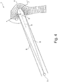
- an adjusting ring 1 comprises at least one recess 2, wherein the recesses 2 have two lateral flanks 3,3 'and a base 4.
- both flanks 3,3 'of the recess 2 shown have a curved shape
- both flanks 3,3' show a polygonal transition to the adjusting ring 1.
- this can also be rounded.
- one of the flanks 3 corresponds to the mirror image of the other flank 3 'relative to a mirror plane 5 extending in the middle of both flanks 3,3', which at the same time forms a radial plane of the adjusting ring 1.
- the base 4 of the recess 2 also has a curved shape, wherein the angles of curvature of the flanks 3,3 'and the base 4 differ in that the base 4 has a greater curvature.
- flanks 3,3 ' according to the Fig. 1 can also be a fixation of the respective blade lever head in the radial direction in the associated recess 2.
- Fig. 2 shows an alternative embodiment of the flanks 3,3 'of the recess 2, which have a square transition to the adjusting ring 1.
- the flanks 3,3 'here are flat and have a predetermined deviation from a parallel arrangement, so that they show an inclination to each other and touch in a pointed bottom 4.
- Fig. 3 shows a further embodiment of an adjusting ring 1 according to the invention, the recess 2, a flat edge 3 and a curved edge 3 ', wherein both flanks 3,3' have a polygonal transition to the adjusting ring.
- the curved edge 3 ' touches the flat edge 3 in the bottom 4 of the recess 4, whereby a curved base 4 of the recess 2 is formed.
- the transition between the adjusting ring 1 and the recess 2 is rounded.
- the transition to a flank 3 has a different rounding, as the transition to the other edge 3 '.
- the flanks 3,3 ' are each plane, wherein they differ from a parallel arrangement such that they lie on radial planes 6 which extend through the center 7 of the adjusting ring 1.
- the flat edges 3,3 ', which lie on the levels 6, run together in a curved and rounded base 4 of the associated recess 2.
- the flanks 3,3 ' are further designed such that one of the flanks 3' corresponds to the mirror image of the other flank 3 with respect to a mirror plane 5 extending in the middle of both flanks 3,3 '.
- flanks 3,3 ' a transfer of an adjusting force on the flanks 3,3' on to improve the corresponding blade lever heads.
- the flanks 3,3 ' are designed such that their shape and arrangement ensure a substantially orthogonal support of the associated blade lever head, regardless of the position of the respective guide vanes and thus of the blade lever head.
- the introduction of force between the lever head and the adjusting ring 1 takes place in the circumferential direction (tangential) of the adjusting ring. 1
Landscapes
- Engineering & Computer Science (AREA)
- Mechanical Engineering (AREA)
- General Engineering & Computer Science (AREA)
- Structures Of Non-Positive Displacement Pumps (AREA)
- Supercharger (AREA)
Applications Claiming Priority (1)
| Application Number | Priority Date | Filing Date | Title |
|---|---|---|---|
| DE102011005556A DE102011005556A1 (de) | 2011-03-15 | 2011-03-15 | Verstellring |
Publications (2)
| Publication Number | Publication Date |
|---|---|
| EP2500526A1 true EP2500526A1 (fr) | 2012-09-19 |
| EP2500526B1 EP2500526B1 (fr) | 2015-04-08 |
Family
ID=45655447
Family Applications (1)
| Application Number | Title | Priority Date | Filing Date |
|---|---|---|---|
| EP12154460.5A Not-in-force EP2500526B1 (fr) | 2011-03-15 | 2012-02-08 | Bague de réglage d'un dispositif de suralimentation |
Country Status (3)
| Country | Link |
|---|---|
| US (1) | US20120237339A1 (fr) |
| EP (1) | EP2500526B1 (fr) |
| DE (1) | DE102011005556A1 (fr) |
Cited By (1)
| Publication number | Priority date | Publication date | Assignee | Title |
|---|---|---|---|---|
| DE102013000499A1 (de) | 2013-01-12 | 2014-07-17 | Daimler Ag | Verstelleinrichtung für einen Abgasturbolader |
Families Citing this family (3)
| Publication number | Priority date | Publication date | Assignee | Title |
|---|---|---|---|---|
| DE102009057664A1 (de) * | 2009-12-09 | 2011-06-16 | Ihi Charging Systems International Gmbh | Verstelleinrichtung für eine Aufladeeinrichtung, insbesondere für einen Abgasturbolader |
| JP2021008819A (ja) * | 2017-10-06 | 2021-01-28 | 株式会社Ihi | 可変容量機構 |
| WO2020225898A1 (fr) * | 2019-05-09 | 2020-11-12 | 三菱重工エンジン&ターボチャージャ株式会社 | Turbocompresseur d'échappement de type à capacité variable |
Citations (10)
| Publication number | Priority date | Publication date | Assignee | Title |
|---|---|---|---|---|
| DE10316389B3 (de) * | 2003-04-10 | 2004-01-22 | Mtu Friedrichshafen Gmbh | Leiteinrichtung für einen Abgasturbolader |
| DE102004023209A1 (de) | 2004-05-11 | 2005-12-08 | Volkswagen Ag | Abgasturbolader für eine Brennkraftmaschine mit variabler Turbinengeometrie |
| DE102004043928A1 (de) * | 2004-09-11 | 2006-04-13 | Ihi Charging Systems International Gmbh | Stelleinrichtung für Leitschaufeln eines Abgasturboladers |
| DE102006048514B3 (de) * | 2005-12-01 | 2007-05-10 | Mtu Friedrichshafen Gmbh | Leiteinrichtung für einen VTG-Abgasturbolader |
| JP2008215259A (ja) * | 2007-03-06 | 2008-09-18 | Toyota Motor Corp | 可変ノズル式ターボチャージャ |
| DE102007022356A1 (de) | 2007-05-12 | 2008-11-13 | Mahle International Gmbh | Ladeeinrichtung |
| EP2039890A2 (fr) * | 2007-09-21 | 2009-03-25 | Kabushiki Kaisha Toyota Jidoshokki | Turbocompresseur doté d'un mécanisme de buse variable |
| DE102009032452A1 (de) * | 2009-07-09 | 2011-01-13 | Bosch Mahle Turbo Systems Gmbh & Co. Kg | Ladeeinrichtung |
| DE102010038185A1 (de) * | 2009-10-27 | 2011-05-05 | Hyundai Motor Co. | Düseneinrichtung eines Turboladers variabler Geometrie |
| EP2348195A2 (fr) * | 2009-12-15 | 2011-07-27 | Honeywell International Inc. | Turbocompresseur à géométrie variable et éléments d'actionnement des ailettes pour un tel turbocompresseur |
Family Cites Families (4)
| Publication number | Priority date | Publication date | Assignee | Title |
|---|---|---|---|---|
| GB2164099B (en) * | 1984-06-29 | 1988-04-13 | Ishikawajima Harima Heavy Ind | Variable capacity turbochargers |
| JP3933455B2 (ja) * | 2001-11-30 | 2007-06-20 | 株式会社小松製作所 | 可変ターボ過給機 |
| DE50209912D1 (de) * | 2002-04-26 | 2007-05-24 | Borgwarner Inc | Turbokompressor mit verstellbaren Leitschaufeln |
| DE602004012000T2 (de) * | 2004-11-08 | 2009-02-12 | Honeywell International Inc. | Verdichter mit variabler geometrie |
-
2011
- 2011-03-15 DE DE102011005556A patent/DE102011005556A1/de not_active Withdrawn
-
2012
- 2012-02-08 EP EP12154460.5A patent/EP2500526B1/fr not_active Not-in-force
- 2012-03-15 US US13/420,796 patent/US20120237339A1/en not_active Abandoned
Patent Citations (10)
| Publication number | Priority date | Publication date | Assignee | Title |
|---|---|---|---|---|
| DE10316389B3 (de) * | 2003-04-10 | 2004-01-22 | Mtu Friedrichshafen Gmbh | Leiteinrichtung für einen Abgasturbolader |
| DE102004023209A1 (de) | 2004-05-11 | 2005-12-08 | Volkswagen Ag | Abgasturbolader für eine Brennkraftmaschine mit variabler Turbinengeometrie |
| DE102004043928A1 (de) * | 2004-09-11 | 2006-04-13 | Ihi Charging Systems International Gmbh | Stelleinrichtung für Leitschaufeln eines Abgasturboladers |
| DE102006048514B3 (de) * | 2005-12-01 | 2007-05-10 | Mtu Friedrichshafen Gmbh | Leiteinrichtung für einen VTG-Abgasturbolader |
| JP2008215259A (ja) * | 2007-03-06 | 2008-09-18 | Toyota Motor Corp | 可変ノズル式ターボチャージャ |
| DE102007022356A1 (de) | 2007-05-12 | 2008-11-13 | Mahle International Gmbh | Ladeeinrichtung |
| EP2039890A2 (fr) * | 2007-09-21 | 2009-03-25 | Kabushiki Kaisha Toyota Jidoshokki | Turbocompresseur doté d'un mécanisme de buse variable |
| DE102009032452A1 (de) * | 2009-07-09 | 2011-01-13 | Bosch Mahle Turbo Systems Gmbh & Co. Kg | Ladeeinrichtung |
| DE102010038185A1 (de) * | 2009-10-27 | 2011-05-05 | Hyundai Motor Co. | Düseneinrichtung eines Turboladers variabler Geometrie |
| EP2348195A2 (fr) * | 2009-12-15 | 2011-07-27 | Honeywell International Inc. | Turbocompresseur à géométrie variable et éléments d'actionnement des ailettes pour un tel turbocompresseur |
Cited By (1)
| Publication number | Priority date | Publication date | Assignee | Title |
|---|---|---|---|---|
| DE102013000499A1 (de) | 2013-01-12 | 2014-07-17 | Daimler Ag | Verstelleinrichtung für einen Abgasturbolader |
Also Published As
| Publication number | Publication date |
|---|---|
| DE102011005556A1 (de) | 2012-09-20 |
| US20120237339A1 (en) | 2012-09-20 |
| EP2500526B1 (fr) | 2015-04-08 |
Similar Documents
| Publication | Publication Date | Title |
|---|---|---|
| EP2398671B1 (fr) | Ferrure pour siège de véhicule | |
| EP2500526B1 (fr) | Bague de réglage d'un dispositif de suralimentation | |
| CH704105B1 (de) | Mehrstufige Gasturbine. | |
| EP1357255B1 (fr) | Turbocompresseur avec distributeur à géométrie variable | |
| DE102016226036A1 (de) | Ladeeinrichtung | |
| DE102008058082A1 (de) | Vorrichtung zur Drehfestlegung eines Drehmomentwandlers mit abgeschlossenem Kolben | |
| EP1515001B1 (fr) | Dispositif de connexion pour les aubes de rotor d'une turbomachine | |
| EP3128181A1 (fr) | Roue de compresseur pour une turbosoufflante de gaz d'echappement | |
| WO2013020643A1 (fr) | Élément de construction | |
| DE102011077626A1 (de) | Wastegate-Ventilvorrichtung | |
| EP2696039B1 (fr) | Étage de turbine à gaz | |
| DE102007022356A1 (de) | Ladeeinrichtung | |
| DE102008049005A1 (de) | Ladeeinrichtung | |
| EP3073063B1 (fr) | Dispositif de charge et aube directrice associée | |
| EP3176385B1 (fr) | Boitier de stator pour une turbomachine et turbomachine comprenant un boitier de stator | |
| DE10257044A1 (de) | Gasturbine und Leitschaufelgitter für eine Gasturbine | |
| DE102009008532A1 (de) | Ladeeinrichtung | |
| EP2317081A2 (fr) | Turbines et/ou compresseurs à géométrie variable | |
| DE102011085703A1 (de) | Variable Turbinen-/Verdichtergeometrie | |
| DE102011077135A1 (de) | Variable Turbinen-/Verdichtergeometrie | |
| DE102010018740A1 (de) | Ladeeinrichtung | |
| EP3146209B1 (fr) | Machine à pistons axiaux | |
| DE102010004622A1 (de) | Variable Turbinen- und/oder Verdichtergeometrie | |
| DE102010053077A1 (de) | Turbine für eine Strömungsmaschine | |
| DE112020000651B4 (de) | Variable Düseneinheit |
Legal Events
| Date | Code | Title | Description |
|---|---|---|---|
| PUAI | Public reference made under article 153(3) epc to a published international application that has entered the european phase |
Free format text: ORIGINAL CODE: 0009012 |
|
| AK | Designated contracting states |
Kind code of ref document: A1 Designated state(s): AL AT BE BG CH CY CZ DE DK EE ES FI FR GB GR HR HU IE IS IT LI LT LU LV MC MK MT NL NO PL PT RO RS SE SI SK SM TR |
|
| AX | Request for extension of the european patent |
Extension state: BA ME |
|
| 17P | Request for examination filed |
Effective date: 20130107 |
|
| GRAP | Despatch of communication of intention to grant a patent |
Free format text: ORIGINAL CODE: EPIDOSNIGR1 |
|
| INTG | Intention to grant announced |
Effective date: 20141126 |
|
| GRAS | Grant fee paid |
Free format text: ORIGINAL CODE: EPIDOSNIGR3 |
|
| GRAA | (expected) grant |
Free format text: ORIGINAL CODE: 0009210 |
|
| AK | Designated contracting states |
Kind code of ref document: B1 Designated state(s): AL AT BE BG CH CY CZ DE DK EE ES FI FR GB GR HR HU IE IS IT LI LT LU LV MC MK MT NL NO PL PT RO RS SE SI SK SM TR |
|
| REG | Reference to a national code |
Ref country code: GB Ref legal event code: FG4D Free format text: NOT ENGLISH |
|
| REG | Reference to a national code |
Ref country code: CH Ref legal event code: EP |
|
| REG | Reference to a national code |
Ref country code: IE Ref legal event code: FG4D Free format text: LANGUAGE OF EP DOCUMENT: GERMAN |
|
| REG | Reference to a national code |
Ref country code: AT Ref legal event code: REF Ref document number: 720746 Country of ref document: AT Kind code of ref document: T Effective date: 20150515 |
|
| REG | Reference to a national code |
Ref country code: DE Ref legal event code: R096 Ref document number: 502012002755 Country of ref document: DE Effective date: 20150521 |
|
| REG | Reference to a national code |
Ref country code: NL Ref legal event code: VDEP Effective date: 20150408 |
|
| REG | Reference to a national code |
Ref country code: LT Ref legal event code: MG4D |
|
| PG25 | Lapsed in a contracting state [announced via postgrant information from national office to epo] |
Ref country code: NL Free format text: LAPSE BECAUSE OF FAILURE TO SUBMIT A TRANSLATION OF THE DESCRIPTION OR TO PAY THE FEE WITHIN THE PRESCRIBED TIME-LIMIT Effective date: 20150408 |
|
| PG25 | Lapsed in a contracting state [announced via postgrant information from national office to epo] |
Ref country code: LT Free format text: LAPSE BECAUSE OF FAILURE TO SUBMIT A TRANSLATION OF THE DESCRIPTION OR TO PAY THE FEE WITHIN THE PRESCRIBED TIME-LIMIT Effective date: 20150408 Ref country code: ES Free format text: LAPSE BECAUSE OF FAILURE TO SUBMIT A TRANSLATION OF THE DESCRIPTION OR TO PAY THE FEE WITHIN THE PRESCRIBED TIME-LIMIT Effective date: 20150408 Ref country code: HR Free format text: LAPSE BECAUSE OF FAILURE TO SUBMIT A TRANSLATION OF THE DESCRIPTION OR TO PAY THE FEE WITHIN THE PRESCRIBED TIME-LIMIT Effective date: 20150408 Ref country code: FI Free format text: LAPSE BECAUSE OF FAILURE TO SUBMIT A TRANSLATION OF THE DESCRIPTION OR TO PAY THE FEE WITHIN THE PRESCRIBED TIME-LIMIT Effective date: 20150408 Ref country code: PT Free format text: LAPSE BECAUSE OF FAILURE TO SUBMIT A TRANSLATION OF THE DESCRIPTION OR TO PAY THE FEE WITHIN THE PRESCRIBED TIME-LIMIT Effective date: 20150810 Ref country code: NO Free format text: LAPSE BECAUSE OF FAILURE TO SUBMIT A TRANSLATION OF THE DESCRIPTION OR TO PAY THE FEE WITHIN THE PRESCRIBED TIME-LIMIT Effective date: 20150708 |
|
| PG25 | Lapsed in a contracting state [announced via postgrant information from national office to epo] |
Ref country code: LV Free format text: LAPSE BECAUSE OF FAILURE TO SUBMIT A TRANSLATION OF THE DESCRIPTION OR TO PAY THE FEE WITHIN THE PRESCRIBED TIME-LIMIT Effective date: 20150408 Ref country code: GR Free format text: LAPSE BECAUSE OF FAILURE TO SUBMIT A TRANSLATION OF THE DESCRIPTION OR TO PAY THE FEE WITHIN THE PRESCRIBED TIME-LIMIT Effective date: 20150709 Ref country code: RS Free format text: LAPSE BECAUSE OF FAILURE TO SUBMIT A TRANSLATION OF THE DESCRIPTION OR TO PAY THE FEE WITHIN THE PRESCRIBED TIME-LIMIT Effective date: 20150408 Ref country code: IS Free format text: LAPSE BECAUSE OF FAILURE TO SUBMIT A TRANSLATION OF THE DESCRIPTION OR TO PAY THE FEE WITHIN THE PRESCRIBED TIME-LIMIT Effective date: 20150808 |
|
| REG | Reference to a national code |
Ref country code: DE Ref legal event code: R097 Ref document number: 502012002755 Country of ref document: DE |
|
| PG25 | Lapsed in a contracting state [announced via postgrant information from national office to epo] |
Ref country code: DK Free format text: LAPSE BECAUSE OF FAILURE TO SUBMIT A TRANSLATION OF THE DESCRIPTION OR TO PAY THE FEE WITHIN THE PRESCRIBED TIME-LIMIT Effective date: 20150408 Ref country code: EE Free format text: LAPSE BECAUSE OF FAILURE TO SUBMIT A TRANSLATION OF THE DESCRIPTION OR TO PAY THE FEE WITHIN THE PRESCRIBED TIME-LIMIT Effective date: 20150408 |
|
| PLBE | No opposition filed within time limit |
Free format text: ORIGINAL CODE: 0009261 |
|
| STAA | Information on the status of an ep patent application or granted ep patent |
Free format text: STATUS: NO OPPOSITION FILED WITHIN TIME LIMIT |
|
| PG25 | Lapsed in a contracting state [announced via postgrant information from national office to epo] |
Ref country code: RO Free format text: LAPSE BECAUSE OF NON-PAYMENT OF DUE FEES Effective date: 20150408 Ref country code: SK Free format text: LAPSE BECAUSE OF FAILURE TO SUBMIT A TRANSLATION OF THE DESCRIPTION OR TO PAY THE FEE WITHIN THE PRESCRIBED TIME-LIMIT Effective date: 20150408 Ref country code: CZ Free format text: LAPSE BECAUSE OF FAILURE TO SUBMIT A TRANSLATION OF THE DESCRIPTION OR TO PAY THE FEE WITHIN THE PRESCRIBED TIME-LIMIT Effective date: 20150408 Ref country code: PL Free format text: LAPSE BECAUSE OF FAILURE TO SUBMIT A TRANSLATION OF THE DESCRIPTION OR TO PAY THE FEE WITHIN THE PRESCRIBED TIME-LIMIT Effective date: 20150408 |
|
| REG | Reference to a national code |
Ref country code: FR Ref legal event code: PLFP Year of fee payment: 5 |
|
| 26N | No opposition filed |
Effective date: 20160111 |
|
| PG25 | Lapsed in a contracting state [announced via postgrant information from national office to epo] |
Ref country code: IT Free format text: LAPSE BECAUSE OF FAILURE TO SUBMIT A TRANSLATION OF THE DESCRIPTION OR TO PAY THE FEE WITHIN THE PRESCRIBED TIME-LIMIT Effective date: 20150408 |
|
| PG25 | Lapsed in a contracting state [announced via postgrant information from national office to epo] |
Ref country code: BE Free format text: LAPSE BECAUSE OF NON-PAYMENT OF DUE FEES Effective date: 20160229 Ref country code: SI Free format text: LAPSE BECAUSE OF FAILURE TO SUBMIT A TRANSLATION OF THE DESCRIPTION OR TO PAY THE FEE WITHIN THE PRESCRIBED TIME-LIMIT Effective date: 20150408 |
|
| PG25 | Lapsed in a contracting state [announced via postgrant information from national office to epo] |
Ref country code: LU Free format text: LAPSE BECAUSE OF FAILURE TO SUBMIT A TRANSLATION OF THE DESCRIPTION OR TO PAY THE FEE WITHIN THE PRESCRIBED TIME-LIMIT Effective date: 20160208 Ref country code: MC Free format text: LAPSE BECAUSE OF FAILURE TO SUBMIT A TRANSLATION OF THE DESCRIPTION OR TO PAY THE FEE WITHIN THE PRESCRIBED TIME-LIMIT Effective date: 20150408 |
|
| REG | Reference to a national code |
Ref country code: CH Ref legal event code: PL |
|
| PG25 | Lapsed in a contracting state [announced via postgrant information from national office to epo] |
Ref country code: CH Free format text: LAPSE BECAUSE OF NON-PAYMENT OF DUE FEES Effective date: 20160229 Ref country code: LI Free format text: LAPSE BECAUSE OF NON-PAYMENT OF DUE FEES Effective date: 20160229 |
|
| REG | Reference to a national code |
Ref country code: IE Ref legal event code: MM4A |
|
| PG25 | Lapsed in a contracting state [announced via postgrant information from national office to epo] |
Ref country code: IE Free format text: LAPSE BECAUSE OF NON-PAYMENT OF DUE FEES Effective date: 20160208 |
|
| REG | Reference to a national code |
Ref country code: FR Ref legal event code: PLFP Year of fee payment: 6 |
|
| PG25 | Lapsed in a contracting state [announced via postgrant information from national office to epo] |
Ref country code: SE Free format text: LAPSE BECAUSE OF FAILURE TO SUBMIT A TRANSLATION OF THE DESCRIPTION OR TO PAY THE FEE WITHIN THE PRESCRIBED TIME-LIMIT Effective date: 20150408 |
|
| PG25 | Lapsed in a contracting state [announced via postgrant information from national office to epo] |
Ref country code: MT Free format text: LAPSE BECAUSE OF FAILURE TO SUBMIT A TRANSLATION OF THE DESCRIPTION OR TO PAY THE FEE WITHIN THE PRESCRIBED TIME-LIMIT Effective date: 20150408 |
|
| REG | Reference to a national code |
Ref country code: FR Ref legal event code: PLFP Year of fee payment: 7 |
|
| REG | Reference to a national code |
Ref country code: AT Ref legal event code: MM01 Ref document number: 720746 Country of ref document: AT Kind code of ref document: T Effective date: 20170208 |
|
| PG25 | Lapsed in a contracting state [announced via postgrant information from national office to epo] |
Ref country code: HU Free format text: LAPSE BECAUSE OF FAILURE TO SUBMIT A TRANSLATION OF THE DESCRIPTION OR TO PAY THE FEE WITHIN THE PRESCRIBED TIME-LIMIT; INVALID AB INITIO Effective date: 20120208 Ref country code: AT Free format text: LAPSE BECAUSE OF NON-PAYMENT OF DUE FEES Effective date: 20170208 Ref country code: CY Free format text: LAPSE BECAUSE OF FAILURE TO SUBMIT A TRANSLATION OF THE DESCRIPTION OR TO PAY THE FEE WITHIN THE PRESCRIBED TIME-LIMIT Effective date: 20150408 Ref country code: SM Free format text: LAPSE BECAUSE OF FAILURE TO SUBMIT A TRANSLATION OF THE DESCRIPTION OR TO PAY THE FEE WITHIN THE PRESCRIBED TIME-LIMIT Effective date: 20150408 |
|
| REG | Reference to a national code |
Ref country code: DE Ref legal event code: R082 Ref document number: 502012002755 Country of ref document: DE Representative=s name: BRP RENAUD UND PARTNER MBB RECHTSANWAELTE PATE, DE Ref country code: DE Ref legal event code: R081 Ref document number: 502012002755 Country of ref document: DE Owner name: BMTS TECHNOLOGY GMBH & CO. KG, DE Free format text: FORMER OWNER: BOSCH MAHLE TURBO SYSTEMS GMBH & CO. KG, 70376 STUTTGART, DE |
|
| PG25 | Lapsed in a contracting state [announced via postgrant information from national office to epo] |
Ref country code: TR Free format text: LAPSE BECAUSE OF FAILURE TO SUBMIT A TRANSLATION OF THE DESCRIPTION OR TO PAY THE FEE WITHIN THE PRESCRIBED TIME-LIMIT Effective date: 20150408 Ref country code: MK Free format text: LAPSE BECAUSE OF FAILURE TO SUBMIT A TRANSLATION OF THE DESCRIPTION OR TO PAY THE FEE WITHIN THE PRESCRIBED TIME-LIMIT Effective date: 20150408 |
|
| PG25 | Lapsed in a contracting state [announced via postgrant information from national office to epo] |
Ref country code: BG Free format text: LAPSE BECAUSE OF FAILURE TO SUBMIT A TRANSLATION OF THE DESCRIPTION OR TO PAY THE FEE WITHIN THE PRESCRIBED TIME-LIMIT Effective date: 20150408 |
|
| PG25 | Lapsed in a contracting state [announced via postgrant information from national office to epo] |
Ref country code: AL Free format text: LAPSE BECAUSE OF FAILURE TO SUBMIT A TRANSLATION OF THE DESCRIPTION OR TO PAY THE FEE WITHIN THE PRESCRIBED TIME-LIMIT Effective date: 20150408 |
|
| PGFP | Annual fee paid to national office [announced via postgrant information from national office to epo] |
Ref country code: GB Payment date: 20200226 Year of fee payment: 9 |
|
| PGFP | Annual fee paid to national office [announced via postgrant information from national office to epo] |
Ref country code: FR Payment date: 20200225 Year of fee payment: 9 |
|
| PGFP | Annual fee paid to national office [announced via postgrant information from national office to epo] |
Ref country code: DE Payment date: 20200429 Year of fee payment: 9 |
|
| REG | Reference to a national code |
Ref country code: DE Ref legal event code: R119 Ref document number: 502012002755 Country of ref document: DE |
|
| GBPC | Gb: european patent ceased through non-payment of renewal fee |
Effective date: 20210208 |
|
| PG25 | Lapsed in a contracting state [announced via postgrant information from national office to epo] |
Ref country code: DE Free format text: LAPSE BECAUSE OF NON-PAYMENT OF DUE FEES Effective date: 20210901 Ref country code: GB Free format text: LAPSE BECAUSE OF NON-PAYMENT OF DUE FEES Effective date: 20210208 Ref country code: FR Free format text: LAPSE BECAUSE OF NON-PAYMENT OF DUE FEES Effective date: 20210228 |