EP2500559B1 - Dispositif de démarrage pour moteur à combustion interne, notamment lanceur à rappel - Google Patents
Dispositif de démarrage pour moteur à combustion interne, notamment lanceur à rappel Download PDFInfo
- Publication number
- EP2500559B1 EP2500559B1 EP12155463.8A EP12155463A EP2500559B1 EP 2500559 B1 EP2500559 B1 EP 2500559B1 EP 12155463 A EP12155463 A EP 12155463A EP 2500559 B1 EP2500559 B1 EP 2500559B1
- Authority
- EP
- European Patent Office
- Prior art keywords
- starter
- coupling member
- cable
- pulley
- spring
- Prior art date
- Legal status (The legal status is an assumption and is not a legal conclusion. Google has not performed a legal analysis and makes no representation as to the accuracy of the status listed.)
- Not-in-force
Links
- 239000007858 starting material Substances 0.000 title claims description 23
- 238000002485 combustion reaction Methods 0.000 title claims description 10
- 230000008878 coupling Effects 0.000 claims description 31
- 238000010168 coupling process Methods 0.000 claims description 31
- 238000005859 coupling reaction Methods 0.000 claims description 31
- 238000013016 damping Methods 0.000 claims description 23
- 230000005540 biological transmission Effects 0.000 claims description 11
- 230000000750 progressive effect Effects 0.000 claims description 4
- 238000004804 winding Methods 0.000 claims description 3
- 238000006243 chemical reaction Methods 0.000 description 3
- 230000006835 compression Effects 0.000 description 3
- 238000007906 compression Methods 0.000 description 3
- 238000001816 cooling Methods 0.000 description 3
- 230000033001 locomotion Effects 0.000 description 3
- 239000000463 material Substances 0.000 description 3
- 239000004033 plastic Substances 0.000 description 3
- 238000000034 method Methods 0.000 description 2
- 238000009423 ventilation Methods 0.000 description 2
- XAGFODPZIPBFFR-UHFFFAOYSA-N aluminium Chemical compound [Al] XAGFODPZIPBFFR-UHFFFAOYSA-N 0.000 description 1
- 229910052782 aluminium Inorganic materials 0.000 description 1
- 238000010276 construction Methods 0.000 description 1
- 230000007423 decrease Effects 0.000 description 1
- 230000000694 effects Effects 0.000 description 1
- 230000001404 mediated effect Effects 0.000 description 1
- 239000002990 reinforced plastic Substances 0.000 description 1
Images


Classifications
-
- F—MECHANICAL ENGINEERING; LIGHTING; HEATING; WEAPONS; BLASTING
- F02—COMBUSTION ENGINES; HOT-GAS OR COMBUSTION-PRODUCT ENGINE PLANTS
- F02N—STARTING OF COMBUSTION ENGINES; STARTING AIDS FOR SUCH ENGINES, NOT OTHERWISE PROVIDED FOR
- F02N3/00—Other muscle-operated starting apparatus
- F02N3/02—Other muscle-operated starting apparatus having pull-cords
-
- F—MECHANICAL ENGINEERING; LIGHTING; HEATING; WEAPONS; BLASTING
- F02—COMBUSTION ENGINES; HOT-GAS OR COMBUSTION-PRODUCT ENGINE PLANTS
- F02N—STARTING OF COMBUSTION ENGINES; STARTING AIDS FOR SUCH ENGINES, NOT OTHERWISE PROVIDED FOR
- F02N15/00—Other power-operated starting apparatus; Component parts, details, or accessories, not provided for in, or of interest apart from groups F02N5/00 - F02N13/00
- F02N15/02—Gearing between starting-engines and started engines; Engagement or disengagement thereof
- F02N15/04—Gearing between starting-engines and started engines; Engagement or disengagement thereof the gearing including disengaging toothed gears
- F02N15/06—Gearing between starting-engines and started engines; Engagement or disengagement thereof the gearing including disengaging toothed gears the toothed gears being moved by axial displacement
- F02N15/062—Starter drives
- F02N15/063—Starter drives with resilient shock absorbers
-
- F—MECHANICAL ENGINEERING; LIGHTING; HEATING; WEAPONS; BLASTING
- F02—COMBUSTION ENGINES; HOT-GAS OR COMBUSTION-PRODUCT ENGINE PLANTS
- F02N—STARTING OF COMBUSTION ENGINES; STARTING AIDS FOR SUCH ENGINES, NOT OTHERWISE PROVIDED FOR
- F02N15/00—Other power-operated starting apparatus; Component parts, details, or accessories, not provided for in, or of interest apart from groups F02N5/00 - F02N13/00
- F02N15/02—Gearing between starting-engines and started engines; Engagement or disengagement thereof
- F02N15/04—Gearing between starting-engines and started engines; Engagement or disengagement thereof the gearing including disengaging toothed gears
- F02N15/06—Gearing between starting-engines and started engines; Engagement or disengagement thereof the gearing including disengaging toothed gears the toothed gears being moved by axial displacement
- F02N15/062—Starter drives
- F02N15/065—Starter drives with blocking means
-
- F—MECHANICAL ENGINEERING; LIGHTING; HEATING; WEAPONS; BLASTING
- F02—COMBUSTION ENGINES; HOT-GAS OR COMBUSTION-PRODUCT ENGINE PLANTS
- F02N—STARTING OF COMBUSTION ENGINES; STARTING AIDS FOR SUCH ENGINES, NOT OTHERWISE PROVIDED FOR
- F02N5/00—Starting apparatus having mechanical power storage
- F02N5/02—Starting apparatus having mechanical power storage of spring type
Definitions
- the invention relates to a starting device for at least one internal combustion engine, in particular cable pull start device for at least a two-stroke or four-stroke engine, with at least one rotatably mounted in a housing pulley or cable drum for generating a driving torque for a crankshaft by means of at least one Anwerfergriffs or pull handle on at least one power transmission means, in particular via a starter cable or traction cable, in rotation and at least one elastic coupling member with at least one driver member, in particular with at least one pawl, connected by means of which the drive torque is transferable to the crankshaft, the coupling member has two ends, wherein one end engages with the driver member and another end engages the sheave or drum.
- a starting device for an internal combustion engine in particular a cable start device for an internal combustion engine, in particular for a two-stroke or four-stroke engine, often caused problems in the past, because at startup by the compression in the engine periodically high reaction forces occur, whereby changing and passing very high forces act on the hand of the operator.
- the spring force of the coupling element acts on the pulley or cable drum, so that it must be robust and thus made heavy.
- the coupling element acts directly on the power transmission means in the pulley or the cable drum and thus the material load in the pulley or the cable drum is greatly reduced.
- a lightweight construction of the pulley is possible, whereby the whole starting device is easier. Since such starting devices are often used in devices such as motor chain saws that already have a significant weight anyway, any weight saving is desired.
- reinforced plastic or aluminum could now be used.
- the EP 1 865 196 A1 discloses a starting device for at least one internal combustion engine with at least one rotatably mounted in a housing pulley or cable drum, for generating a driving torque for a crankshaft by means of at least one Anwerfergrills or access, via at least one force transmission means in rotation and at least one elastic coupling member with at least one Driver member is connected, by means of which the drive torque is transferable to the crankshaft, the coupling member has two ends, wherein one end with the driver member and another end with the sheave or the cable drum is engaged, wherein the coupling member is provided a rotation stop.
- the EP 2 039 926 A1 has a starting device for at least one internal combustion engine having at least one rotatably mounted in a housing pulley or cable drum, for generating a driving torque for a crankshaft by means of at least one ejector handle or pull handle, via at least one force transmission means in rotation displaceable and at least one elastic coupling member with at least a driver member is connected, by means of which the drive torque is transferable to the crankshaft, the coupling member has two ends, wherein one end with the driver member and another end with the sheave or the cable drum is engaged, wherein the coupling member is provided a rotation stop.
- Object of the present invention is now to provide a starting device, which has a long service life when used for different engine sizes.
- the coupling member is now provided in a starter device of the type mentioned in such a way that the coupling member is provided a rotation stop.
- the coupling member may be formed in various ways. Thus, it could be that the coupling member is configured, for example, as a three-dimensional spring, such as wire-wound, cylindrical or conical springs or even band springs. It would also be conceivable that similar to flywheels of car engines tangential springs are arranged on the circumference.
- the force paths can be significantly shortened.
- the components cable drum and / or pulley and / or driver can be designed to save material.
- the rotation stop can now be provided on an end of the coupling element facing the driver element and / or the cable pulley or the cable drum.
- the rotation stop is designed as a damping element, wherein the damping element has a rubber element or a damping spring.
- the damping element has a rubber element, for example, on the two stop sides (during reverse rotation or overload) form a contact surface for the driver.
- the damping element comprise a damping spring.
- This damping spring may be formed for example as a spiral spring and preferably have one or more windings.
- the damping element has a progressive characteristic. If, for example, a rubber damping element is parabolic, it acquires progressive damping properties.
- the damping element is integrally formed with the coupling member.
- a starting device 100 shown is intended for manual starting of an internal combustion engine, the at For example, may belong to a motor chain saw.
- the cable start device 100 is housed in a housing 10, which is a removable, provided with ventilation slots 11 cover of the motor housing, in which inter alia, an air guide 12 is integrated and an adjacent pole wheel thirteenth
- a bearing pin 14 is shown, which is surrounded by a likewise substantially housing-fixed spring housing 15 for a helical, on the edge of the spring housing 15 on one side clamped starter spring 16.
- This starter spring 16 serves as a return spring for the pulley or cable drum 17th
- the pulley or cable drum 17 has a rearward pin which projects through a central bore of the spring housing 15 in this and has an axial slot for engagement of the inner end of the helical starter spring 16.
- a starter rope or pull rope (not shown) is wound, the free end of which is led out of the housing 10 and attached to a handle.
- the pulley or cable drum 17 is set under development of the starter rope or pull rope around the bearing pin 14 in motion.
- the pulley or cable drum 17 has a bearing pin 14 surrounding annular receiving space 20 which is limited to the starter spring 16 by an end wall. Between this end wall of the pulley or cable drum 17 and a receiving space of a pawl driver member 25 is a coupling member which is formed here as a spiral spring 26 is arranged.
- the outer, that is, the end wall of the pulley or cable drum 17 facing the end of the coil spring 26 is suspended in a slot 27 which is provided in an annular shoulder of the end wall. This shoulder encloses the coil spring 26, the outer winding rests against the inner wall of the paragraph.
- the Klinkenmitauerglied 25 facing the end of the coil spring 26 is mounted in the pawl Mit supportivemit mandatoryglied 25.
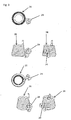
- the coil spring 26, as in Fig.1 is shown in the prior art, represents a cylindrical coil spring, which is on the one hand with the pawl Mit Sprint Sprint 21 and on the other hand with the cable drum or sheave 17 engaged.
- the coil spring 26 form in the form of a truncated cone, the base surface of the pulley or cable drum 17 faces, while the top surface facing the Klinkenmit instructionalglied 25.
- Such a shaped coil spring 26 can lead to a significantly improved ventilation behavior of the internal combustion engine, since the inflow of the cooling air is improved by the starting device 100 in the arranged after the starting device air guide 12, since the conical spring 26 follows the incoming cooling air flow, and thus the cooling air flow positive leads.
- the spring develops a progressive spring characteristic.
- the coil spring 26 is deformed directly when a limit value is exceeded, but it is possible first to let the larger turns go to block to then exploit a progression to use the smaller turns of the coil spring 26, so that here the rotational speed of the ratchet member 25 decreases, while the pulley or cable drum 17 can be further rotated at the same speed and with only moderately increasing force.
- a coil spring 26 is shown, which has according to a preferred embodiment on the pulley or cable drum 17 end facing a provided with a damping element 29 rotation stop.
- the damping element is according to the embodiment shown by Fig. 2 a rubber element.
- a coil spring 26 is shown, which according to a preferred embodiment on the pulley or cable drum 17 end facing a provided with a damping element 29 rotation stop, which is here designed as a damping spring and is thus formed integrally with the coil spring according to the preferred embodiment shown.
Landscapes
- Engineering & Computer Science (AREA)
- Chemical & Material Sciences (AREA)
- Combustion & Propulsion (AREA)
- Mechanical Engineering (AREA)
- General Engineering & Computer Science (AREA)
- Springs (AREA)
- Devices For Conveying Motion By Means Of Endless Flexible Members (AREA)
- Transmission Devices (AREA)
Claims (6)
- Dispositif de démarrage (100) pour au moins un moteur à combustion interne, notamment dispositif de démarreur à câble pour au moins un moteur à deux temps ou un moteur à quatre temps, comportant au moins une poulie ou un tambour pour câble (17) positionné rotativement dans un logement (10), qui pour générer un couple de rotation d'entraînement pour un vilebrequin peut être déplacé en rotation au moyen d'au moins une poignée de lanceur, par l'intermédiaire d'au moins un moyen de transmission de force, notamment par l'intermédiaire d'un câble de démarrage ou câble de traction, et est relié par l'intermédiaire d'au moins un organe de couplage élastique (26) avec au moins un organe d'entraînement (25), notamment avec au moins un entraîneur à cliquet, au moyen duquel le couple de rotation d'entraînement peut être transmis au vilebrequin, l'organe de couplage (26) présente deux extrémités, dans lequel une extrémité vient en prise avec l'organe d'entraînement (25) et une autre extrémité vient en prise avec la poulie ou le tambour pour câble (17), caractérisé en ce que sur l'organe de couplage (26) une butée de rotation (29) est prévue et en ce que la butée de rotation (29) est conçue comme un élément d'amortissement, dans lequel l'élément d'amortissement présente un élément en caoutchouc ou un ressort d'amortissement.
- Dispositif de démarrage selon la revendication 1, caractérisé en ce que l'organe de couplage (26) présente un ressort en trois dimensions.
- Dispositif de démarrage selon la revendication 1 ou 2, caractérisé en ce que la butée de rotation (29) est prévue sur une extrémité de l'organe de couplage (26) tournée vers l'organe d'entraînement (25) et/ou la poulie respectivement le tambour pour câble (17).
- Dispositif de démarrage selon la revendication 1, caractérisé en ce que le ressort d'amortissement présente des spires.
- Dispositif de démarrage selon une des revendications précédentes, caractérisé en ce que l'élément d'amortissement présente une ligne caractéristique progressive.
- Dispositif de démarrage selon une des revendications précédentes, caractérisé en ce que l'élément d'amortissement est conçu en un seul tenant avec 'organe de couplage.
Applications Claiming Priority (1)
| Application Number | Priority Date | Filing Date | Title |
|---|---|---|---|
| DE202011000610U DE202011000610U1 (de) | 2011-03-17 | 2011-03-17 | Startvorrichtung für mindestens eine Verbrennungskraftmaschine, insbesondere Seilzugstartvorrichtung |
Publications (2)
| Publication Number | Publication Date |
|---|---|
| EP2500559A1 EP2500559A1 (fr) | 2012-09-19 |
| EP2500559B1 true EP2500559B1 (fr) | 2015-04-01 |
Family
ID=45655770
Family Applications (1)
| Application Number | Title | Priority Date | Filing Date |
|---|---|---|---|
| EP12155463.8A Not-in-force EP2500559B1 (fr) | 2011-03-17 | 2012-02-14 | Dispositif de démarrage pour moteur à combustion interne, notamment lanceur à rappel |
Country Status (4)
| Country | Link |
|---|---|
| US (1) | US9163599B2 (fr) |
| EP (1) | EP2500559B1 (fr) |
| CN (1) | CN102678418B (fr) |
| DE (1) | DE202011000610U1 (fr) |
Families Citing this family (2)
| Publication number | Priority date | Publication date | Assignee | Title |
|---|---|---|---|---|
| CN103939252A (zh) * | 2014-04-04 | 2014-07-23 | 成都绿迪科技有限公司 | 拉绳启动器 |
| EP3147494A1 (fr) * | 2015-09-22 | 2017-03-29 | Coza International Limited Hongkong | Source de démarreur double source pour un moteur |
Family Cites Families (21)
| Publication number | Priority date | Publication date | Assignee | Title |
|---|---|---|---|---|
| US2477822A (en) * | 1944-02-07 | 1949-08-02 | Henry J Kaiser Company | Vehicle suspension |
| US2592714A (en) * | 1945-10-01 | 1952-04-15 | Gen Steel Castings Corp | Railway truck |
| US2577760A (en) * | 1947-05-08 | 1951-12-11 | Hickman Ind Inc | Spring suspension for vehicles |
| US2820646A (en) * | 1956-07-12 | 1958-01-21 | Kolbe Joachim | Dual turn shackles for banking and non-banking vehicles |
| US4181208A (en) * | 1978-05-18 | 1980-01-01 | General Motors Corporation | Vibration damper with three sets of springs in parallel |
| DE4135405C2 (de) | 1991-10-26 | 2000-08-17 | Stihl Maschf Andreas | Startvorrichtung für Brennkraftmotoren |
| KR100962156B1 (ko) * | 2002-05-20 | 2010-06-10 | 스타팅 고교 가부시키가이샤 | 리코일 시동기 |
| JP4014998B2 (ja) * | 2002-10-21 | 2007-11-28 | スターテング工業株式会社 | リコイルスタータ |
| US20040149249A1 (en) * | 2003-01-29 | 2004-08-05 | Olaf Kruse | Starting device for internal combustion engine |
| JP2005299581A (ja) * | 2004-04-15 | 2005-10-27 | Kyosho Corp | 衝撃吸収機構を備えたギヤ |
| US7191752B2 (en) * | 2004-05-14 | 2007-03-20 | Husqvarna Outdoor Products Inc. | Energy storing starter assembly |
| JP4376193B2 (ja) * | 2005-02-08 | 2009-12-02 | ハスクバーナ・ゼノア株式会社 | エンジン始動装置とエンジンとの間の動力伝達機構 |
| US7267091B2 (en) * | 2005-04-27 | 2007-09-11 | Husqvarna Outdoor Products Inc. | Dynamic effortless pull starting |
| CN101189427B (zh) * | 2005-12-20 | 2011-08-17 | 富世华智诺株式会社 | 发动机起动装置 |
| JP4846469B2 (ja) * | 2006-07-06 | 2011-12-28 | スターテング工業株式会社 | 小型エンジンの始動装置 |
| DE102008007291B4 (de) * | 2008-02-02 | 2016-12-22 | Andreas Stihl Ag & Co. Kg | Starteinrichtung für einen Verbrennungsmotor |
| DE202009011429U1 (de) | 2009-08-25 | 2010-12-30 | Makita Corp., Anjo | Startvorrichtung für Brennkraftmotor |
| DE202009011430U1 (de) | 2009-08-25 | 2010-12-30 | Makita Corp., Anjo | Startvorrichtung für Brennkraftmotor |
| EP2299104B1 (fr) * | 2009-08-25 | 2014-11-12 | Makita Corporation | Dispositif de démarrage pour un moteur à combustion interne |
| WO2012008980A1 (fr) * | 2010-07-14 | 2012-01-19 | Husqvarna Forestry Products N.A., Inc | Dispositif de démarrage pour un moteur à combustion interne |
| DE202010016015U1 (de) * | 2010-11-30 | 2012-03-01 | Makita Corporation | Startvorrichtung für einen Brennkraftmotor |
-
2011
- 2011-03-17 DE DE202011000610U patent/DE202011000610U1/de not_active Expired - Lifetime
-
2012
- 2012-02-14 EP EP12155463.8A patent/EP2500559B1/fr not_active Not-in-force
- 2012-03-01 US US13/409,763 patent/US9163599B2/en not_active Expired - Fee Related
- 2012-03-15 CN CN201210068964.0A patent/CN102678418B/zh not_active Expired - Fee Related
Also Published As
| Publication number | Publication date |
|---|---|
| EP2500559A1 (fr) | 2012-09-19 |
| US9163599B2 (en) | 2015-10-20 |
| US20120234283A1 (en) | 2012-09-20 |
| DE202011000610U9 (de) | 2013-08-22 |
| CN102678418A (zh) | 2012-09-19 |
| DE202011000610U1 (de) | 2012-06-18 |
| CN102678418B (zh) | 2015-10-14 |
Similar Documents
| Publication | Publication Date | Title |
|---|---|---|
| DE4135405C2 (de) | Startvorrichtung für Brennkraftmotoren | |
| DE102009054930B4 (de) | Bohrmaschine | |
| DE102009054927A1 (de) | Handwerkzeugmaschine, insbesondere Akkuhandwerkzeugmaschine | |
| DE20301182U1 (de) | Startvorrichtung für Brennkraftmotor | |
| DE10255913A1 (de) | Vorrichtung zum Dämpfen von Drehschwingungen | |
| EP2299104B1 (fr) | Dispositif de démarrage pour un moteur à combustion interne | |
| EP2500559B1 (fr) | Dispositif de démarrage pour moteur à combustion interne, notamment lanceur à rappel | |
| DE202013100891U1 (de) | Schnittstellenvorsatz für eine Hand-Werkzeugmaschine | |
| DE2423746C2 (de) | Regelbarer Aggregate-Antrieb für Brennkraftmaschinen, insbesondere für Kraftfahrzeug-Brennkraftmaschinen | |
| DE102009017086B4 (de) | Filtertopf mit Drehmomentbegrenzer | |
| EP2142344B1 (fr) | Machine-outil portative | |
| DE102007026988A1 (de) | Zweimassenschwungrad, insbesondere für ein Kraftfahrzeug | |
| EP2253578A1 (fr) | Treuil de charge à entraînement électrique | |
| DE3530194A1 (de) | Handbetaetigter anlasser fuer motoren | |
| DE3133652A1 (de) | Antrieb zum verstellen eines gefuehrten bauelements | |
| DE202009011430U1 (de) | Startvorrichtung für Brennkraftmotor | |
| DE202011000616U1 (de) | Startvorrichtung für Verbrennungskraftmaschinen | |
| DE202009011429U1 (de) | Startvorrichtung für Brennkraftmotor | |
| WO2013190002A1 (fr) | Groupe auxiliaire de commande d'un ou plusieurs dispositifs d'entraînement hydrauliques | |
| DE20319902U1 (de) | Startvorrichtung für Brennkraftmotor | |
| DE102016219943A1 (de) | Nockenwellenversteller zur variablen Ventilsteuerung einer Brennkraftmaschine | |
| DE102024105357B3 (de) | Handgeführtes, motorbetriebenes Arbeitsgerät, insbesondere Benzinmotorsäge | |
| DE102019114099A1 (de) | Pendelspanner / Ringspanner mit variablem Federfußpunkt und Endloszugmitteltrieb | |
| EP0993563B1 (fr) | Servo-moteur pour embrayage | |
| DE102010064368A1 (de) | Handwerkzeugmaschinenspannvorrichtung |
Legal Events
| Date | Code | Title | Description |
|---|---|---|---|
| PUAI | Public reference made under article 153(3) epc to a published international application that has entered the european phase |
Free format text: ORIGINAL CODE: 0009012 |
|
| AK | Designated contracting states |
Kind code of ref document: A1 Designated state(s): AL AT BE BG CH CY CZ DE DK EE ES FI FR GB GR HR HU IE IS IT LI LT LU LV MC MK MT NL NO PL PT RO RS SE SI SK SM TR |
|
| AX | Request for extension of the european patent |
Extension state: BA ME |
|
| 17P | Request for examination filed |
Effective date: 20121210 |
|
| 17Q | First examination report despatched |
Effective date: 20130311 |
|
| GRAP | Despatch of communication of intention to grant a patent |
Free format text: ORIGINAL CODE: EPIDOSNIGR1 |
|
| INTG | Intention to grant announced |
Effective date: 20141028 |
|
| GRAS | Grant fee paid |
Free format text: ORIGINAL CODE: EPIDOSNIGR3 |
|
| GRAA | (expected) grant |
Free format text: ORIGINAL CODE: 0009210 |
|
| AK | Designated contracting states |
Kind code of ref document: B1 Designated state(s): AL AT BE BG CH CY CZ DE DK EE ES FI FR GB GR HR HU IE IS IT LI LT LU LV MC MK MT NL NO PL PT RO RS SE SI SK SM TR |
|
| REG | Reference to a national code |
Ref country code: GB Ref legal event code: FG4D Free format text: NOT ENGLISH |
|
| REG | Reference to a national code |
Ref country code: CH Ref legal event code: EP |
|
| REG | Reference to a national code |
Ref country code: IE Ref legal event code: FG4D Free format text: LANGUAGE OF EP DOCUMENT: GERMAN |
|
| REG | Reference to a national code |
Ref country code: AT Ref legal event code: REF Ref document number: 719241 Country of ref document: AT Kind code of ref document: T Effective date: 20150515 |
|
| REG | Reference to a national code |
Ref country code: DE Ref legal event code: R096 Ref document number: 502012002670 Country of ref document: DE Effective date: 20150521 |
|
| REG | Reference to a national code |
Ref country code: NL Ref legal event code: VDEP Effective date: 20150401 |
|
| REG | Reference to a national code |
Ref country code: LT Ref legal event code: MG4D |
|
| PG25 | Lapsed in a contracting state [announced via postgrant information from national office to epo] |
Ref country code: NL Free format text: LAPSE BECAUSE OF FAILURE TO SUBMIT A TRANSLATION OF THE DESCRIPTION OR TO PAY THE FEE WITHIN THE PRESCRIBED TIME-LIMIT Effective date: 20150401 |
|
| PG25 | Lapsed in a contracting state [announced via postgrant information from national office to epo] |
Ref country code: HR Free format text: LAPSE BECAUSE OF FAILURE TO SUBMIT A TRANSLATION OF THE DESCRIPTION OR TO PAY THE FEE WITHIN THE PRESCRIBED TIME-LIMIT Effective date: 20150401 Ref country code: NO Free format text: LAPSE BECAUSE OF FAILURE TO SUBMIT A TRANSLATION OF THE DESCRIPTION OR TO PAY THE FEE WITHIN THE PRESCRIBED TIME-LIMIT Effective date: 20150701 Ref country code: LT Free format text: LAPSE BECAUSE OF FAILURE TO SUBMIT A TRANSLATION OF THE DESCRIPTION OR TO PAY THE FEE WITHIN THE PRESCRIBED TIME-LIMIT Effective date: 20150401 Ref country code: CZ Free format text: LAPSE BECAUSE OF FAILURE TO SUBMIT A TRANSLATION OF THE DESCRIPTION OR TO PAY THE FEE WITHIN THE PRESCRIBED TIME-LIMIT Effective date: 20150401 Ref country code: FI Free format text: LAPSE BECAUSE OF FAILURE TO SUBMIT A TRANSLATION OF THE DESCRIPTION OR TO PAY THE FEE WITHIN THE PRESCRIBED TIME-LIMIT Effective date: 20150401 Ref country code: PT Free format text: LAPSE BECAUSE OF FAILURE TO SUBMIT A TRANSLATION OF THE DESCRIPTION OR TO PAY THE FEE WITHIN THE PRESCRIBED TIME-LIMIT Effective date: 20150803 Ref country code: ES Free format text: LAPSE BECAUSE OF FAILURE TO SUBMIT A TRANSLATION OF THE DESCRIPTION OR TO PAY THE FEE WITHIN THE PRESCRIBED TIME-LIMIT Effective date: 20150401 |
|
| PG25 | Lapsed in a contracting state [announced via postgrant information from national office to epo] |
Ref country code: GR Free format text: LAPSE BECAUSE OF FAILURE TO SUBMIT A TRANSLATION OF THE DESCRIPTION OR TO PAY THE FEE WITHIN THE PRESCRIBED TIME-LIMIT Effective date: 20150702 Ref country code: LV Free format text: LAPSE BECAUSE OF FAILURE TO SUBMIT A TRANSLATION OF THE DESCRIPTION OR TO PAY THE FEE WITHIN THE PRESCRIBED TIME-LIMIT Effective date: 20150401 Ref country code: IS Free format text: LAPSE BECAUSE OF FAILURE TO SUBMIT A TRANSLATION OF THE DESCRIPTION OR TO PAY THE FEE WITHIN THE PRESCRIBED TIME-LIMIT Effective date: 20150801 Ref country code: RS Free format text: LAPSE BECAUSE OF FAILURE TO SUBMIT A TRANSLATION OF THE DESCRIPTION OR TO PAY THE FEE WITHIN THE PRESCRIBED TIME-LIMIT Effective date: 20150401 |
|
| REG | Reference to a national code |
Ref country code: DE Ref legal event code: R097 Ref document number: 502012002670 Country of ref document: DE |
|
| PG25 | Lapsed in a contracting state [announced via postgrant information from national office to epo] |
Ref country code: DK Free format text: LAPSE BECAUSE OF FAILURE TO SUBMIT A TRANSLATION OF THE DESCRIPTION OR TO PAY THE FEE WITHIN THE PRESCRIBED TIME-LIMIT Effective date: 20150401 Ref country code: EE Free format text: LAPSE BECAUSE OF FAILURE TO SUBMIT A TRANSLATION OF THE DESCRIPTION OR TO PAY THE FEE WITHIN THE PRESCRIBED TIME-LIMIT Effective date: 20150401 |
|
| PLBE | No opposition filed within time limit |
Free format text: ORIGINAL CODE: 0009261 |
|
| STAA | Information on the status of an ep patent application or granted ep patent |
Free format text: STATUS: NO OPPOSITION FILED WITHIN TIME LIMIT |
|
| PG25 | Lapsed in a contracting state [announced via postgrant information from national office to epo] |
Ref country code: PL Free format text: LAPSE BECAUSE OF FAILURE TO SUBMIT A TRANSLATION OF THE DESCRIPTION OR TO PAY THE FEE WITHIN THE PRESCRIBED TIME-LIMIT Effective date: 20150401 Ref country code: RO Free format text: LAPSE BECAUSE OF NON-PAYMENT OF DUE FEES Effective date: 20150401 Ref country code: SK Free format text: LAPSE BECAUSE OF FAILURE TO SUBMIT A TRANSLATION OF THE DESCRIPTION OR TO PAY THE FEE WITHIN THE PRESCRIBED TIME-LIMIT Effective date: 20150401 |
|
| 26N | No opposition filed |
Effective date: 20160105 |
|
| PG25 | Lapsed in a contracting state [announced via postgrant information from national office to epo] |
Ref country code: IT Free format text: LAPSE BECAUSE OF FAILURE TO SUBMIT A TRANSLATION OF THE DESCRIPTION OR TO PAY THE FEE WITHIN THE PRESCRIBED TIME-LIMIT Effective date: 20150401 |
|
| PG25 | Lapsed in a contracting state [announced via postgrant information from national office to epo] |
Ref country code: SI Free format text: LAPSE BECAUSE OF FAILURE TO SUBMIT A TRANSLATION OF THE DESCRIPTION OR TO PAY THE FEE WITHIN THE PRESCRIBED TIME-LIMIT Effective date: 20150401 Ref country code: BE Free format text: LAPSE BECAUSE OF NON-PAYMENT OF DUE FEES Effective date: 20160229 |
|
| PG25 | Lapsed in a contracting state [announced via postgrant information from national office to epo] |
Ref country code: MC Free format text: LAPSE BECAUSE OF FAILURE TO SUBMIT A TRANSLATION OF THE DESCRIPTION OR TO PAY THE FEE WITHIN THE PRESCRIBED TIME-LIMIT Effective date: 20150401 Ref country code: LU Free format text: LAPSE BECAUSE OF FAILURE TO SUBMIT A TRANSLATION OF THE DESCRIPTION OR TO PAY THE FEE WITHIN THE PRESCRIBED TIME-LIMIT Effective date: 20160214 |
|
| REG | Reference to a national code |
Ref country code: CH Ref legal event code: PL |
|
| GBPC | Gb: european patent ceased through non-payment of renewal fee |
Effective date: 20160214 |
|
| PG25 | Lapsed in a contracting state [announced via postgrant information from national office to epo] |
Ref country code: CH Free format text: LAPSE BECAUSE OF NON-PAYMENT OF DUE FEES Effective date: 20160229 Ref country code: LI Free format text: LAPSE BECAUSE OF NON-PAYMENT OF DUE FEES Effective date: 20160229 |
|
| REG | Reference to a national code |
Ref country code: FR Ref legal event code: ST Effective date: 20161028 |
|
| REG | Reference to a national code |
Ref country code: IE Ref legal event code: MM4A |
|
| PG25 | Lapsed in a contracting state [announced via postgrant information from national office to epo] |
Ref country code: FR Free format text: LAPSE BECAUSE OF NON-PAYMENT OF DUE FEES Effective date: 20160229 Ref country code: GB Free format text: LAPSE BECAUSE OF NON-PAYMENT OF DUE FEES Effective date: 20160214 Ref country code: IE Free format text: LAPSE BECAUSE OF NON-PAYMENT OF DUE FEES Effective date: 20160214 |
|
| PG25 | Lapsed in a contracting state [announced via postgrant information from national office to epo] |
Ref country code: SE Free format text: LAPSE BECAUSE OF FAILURE TO SUBMIT A TRANSLATION OF THE DESCRIPTION OR TO PAY THE FEE WITHIN THE PRESCRIBED TIME-LIMIT Effective date: 20150401 |
|
| PG25 | Lapsed in a contracting state [announced via postgrant information from national office to epo] |
Ref country code: MT Free format text: LAPSE BECAUSE OF FAILURE TO SUBMIT A TRANSLATION OF THE DESCRIPTION OR TO PAY THE FEE WITHIN THE PRESCRIBED TIME-LIMIT Effective date: 20150401 |
|
| REG | Reference to a national code |
Ref country code: AT Ref legal event code: MM01 Ref document number: 719241 Country of ref document: AT Kind code of ref document: T Effective date: 20170214 |
|
| PG25 | Lapsed in a contracting state [announced via postgrant information from national office to epo] |
Ref country code: HU Free format text: LAPSE BECAUSE OF FAILURE TO SUBMIT A TRANSLATION OF THE DESCRIPTION OR TO PAY THE FEE WITHIN THE PRESCRIBED TIME-LIMIT; INVALID AB INITIO Effective date: 20120214 Ref country code: SM Free format text: LAPSE BECAUSE OF FAILURE TO SUBMIT A TRANSLATION OF THE DESCRIPTION OR TO PAY THE FEE WITHIN THE PRESCRIBED TIME-LIMIT Effective date: 20150401 Ref country code: AT Free format text: LAPSE BECAUSE OF NON-PAYMENT OF DUE FEES Effective date: 20170214 Ref country code: CY Free format text: LAPSE BECAUSE OF FAILURE TO SUBMIT A TRANSLATION OF THE DESCRIPTION OR TO PAY THE FEE WITHIN THE PRESCRIBED TIME-LIMIT Effective date: 20150401 |
|
| PG25 | Lapsed in a contracting state [announced via postgrant information from national office to epo] |
Ref country code: TR Free format text: LAPSE BECAUSE OF FAILURE TO SUBMIT A TRANSLATION OF THE DESCRIPTION OR TO PAY THE FEE WITHIN THE PRESCRIBED TIME-LIMIT Effective date: 20150401 Ref country code: MK Free format text: LAPSE BECAUSE OF FAILURE TO SUBMIT A TRANSLATION OF THE DESCRIPTION OR TO PAY THE FEE WITHIN THE PRESCRIBED TIME-LIMIT Effective date: 20150401 |
|
| PG25 | Lapsed in a contracting state [announced via postgrant information from national office to epo] |
Ref country code: BG Free format text: LAPSE BECAUSE OF FAILURE TO SUBMIT A TRANSLATION OF THE DESCRIPTION OR TO PAY THE FEE WITHIN THE PRESCRIBED TIME-LIMIT Effective date: 20150401 |
|
| PG25 | Lapsed in a contracting state [announced via postgrant information from national office to epo] |
Ref country code: AL Free format text: LAPSE BECAUSE OF FAILURE TO SUBMIT A TRANSLATION OF THE DESCRIPTION OR TO PAY THE FEE WITHIN THE PRESCRIBED TIME-LIMIT Effective date: 20150401 |
|
| PGFP | Annual fee paid to national office [announced via postgrant information from national office to epo] |
Ref country code: DE Payment date: 20190129 Year of fee payment: 8 |
|
| REG | Reference to a national code |
Ref country code: DE Ref legal event code: R119 Ref document number: 502012002670 Country of ref document: DE |
|
| PG25 | Lapsed in a contracting state [announced via postgrant information from national office to epo] |
Ref country code: DE Free format text: LAPSE BECAUSE OF NON-PAYMENT OF DUE FEES Effective date: 20200901 |