EP2500571B1 - Flügelzellenverdichter - Google Patents
Flügelzellenverdichter Download PDFInfo
- Publication number
- EP2500571B1 EP2500571B1 EP10829808.4A EP10829808A EP2500571B1 EP 2500571 B1 EP2500571 B1 EP 2500571B1 EP 10829808 A EP10829808 A EP 10829808A EP 2500571 B1 EP2500571 B1 EP 2500571B1
- Authority
- EP
- European Patent Office
- Prior art keywords
- rotor
- vane
- compressor
- controller
- cylinder chamber
- Prior art date
- Legal status (The legal status is an assumption and is not a legal conclusion. Google has not performed a legal analysis and makes no representation as to the accuracy of the status listed.)
- Not-in-force
Links
Images



Classifications
-
- F—MECHANICAL ENGINEERING; LIGHTING; HEATING; WEAPONS; BLASTING
- F04—POSITIVE - DISPLACEMENT MACHINES FOR LIQUIDS; PUMPS FOR LIQUIDS OR ELASTIC FLUIDS
- F04C—ROTARY-PISTON, OR OSCILLATING-PISTON, POSITIVE-DISPLACEMENT MACHINES FOR LIQUIDS; ROTARY-PISTON, OR OSCILLATING-PISTON, POSITIVE-DISPLACEMENT PUMPS
- F04C18/00—Rotary-piston pumps specially adapted for elastic fluids
- F04C18/30—Rotary-piston pumps specially adapted for elastic fluids having the characteristics covered by two or more of groups F04C18/02, F04C18/08, F04C18/22, F04C18/24, F04C18/48, or having the characteristics covered by one of these groups together with some other type of movement between co-operating members
- F04C18/34—Rotary-piston pumps specially adapted for elastic fluids having the characteristics covered by two or more of groups F04C18/02, F04C18/08, F04C18/22, F04C18/24, F04C18/48, or having the characteristics covered by one of these groups together with some other type of movement between co-operating members having the movement defined in group F04C18/08 or F04C18/22 and relative reciprocation between the co-operating members
- F04C18/344—Rotary-piston pumps specially adapted for elastic fluids having the characteristics covered by two or more of groups F04C18/02, F04C18/08, F04C18/22, F04C18/24, F04C18/48, or having the characteristics covered by one of these groups together with some other type of movement between co-operating members having the movement defined in group F04C18/08 or F04C18/22 and relative reciprocation between the co-operating members with vanes reciprocating with respect to the inner member
- F04C18/3446—Rotary-piston pumps specially adapted for elastic fluids having the characteristics covered by two or more of groups F04C18/02, F04C18/08, F04C18/22, F04C18/24, F04C18/48, or having the characteristics covered by one of these groups together with some other type of movement between co-operating members having the movement defined in group F04C18/08 or F04C18/22 and relative reciprocation between the co-operating members with vanes reciprocating with respect to the inner member the inner and outer member being in contact along more than one line or surface
-
- F—MECHANICAL ENGINEERING; LIGHTING; HEATING; WEAPONS; BLASTING
- F04—POSITIVE - DISPLACEMENT MACHINES FOR LIQUIDS; PUMPS FOR LIQUIDS OR ELASTIC FLUIDS
- F04C—ROTARY-PISTON, OR OSCILLATING-PISTON, POSITIVE-DISPLACEMENT MACHINES FOR LIQUIDS; ROTARY-PISTON, OR OSCILLATING-PISTON, POSITIVE-DISPLACEMENT PUMPS
- F04C28/00—Control of, monitoring of, or safety arrangements for, pumps or pumping installations specially adapted for elastic fluids
- F04C28/04—Control of, monitoring of, or safety arrangements for, pumps or pumping installations specially adapted for elastic fluids specially adapted for reversible pumps
-
- F—MECHANICAL ENGINEERING; LIGHTING; HEATING; WEAPONS; BLASTING
- F04—POSITIVE - DISPLACEMENT MACHINES FOR LIQUIDS; PUMPS FOR LIQUIDS OR ELASTIC FLUIDS
- F04C—ROTARY-PISTON, OR OSCILLATING-PISTON, POSITIVE-DISPLACEMENT MACHINES FOR LIQUIDS; ROTARY-PISTON, OR OSCILLATING-PISTON, POSITIVE-DISPLACEMENT PUMPS
- F04C28/00—Control of, monitoring of, or safety arrangements for, pumps or pumping installations specially adapted for elastic fluids
- F04C28/06—Control of, monitoring of, or safety arrangements for, pumps or pumping installations specially adapted for elastic fluids specially adapted for stopping, starting, idling or no-load operation
-
- F—MECHANICAL ENGINEERING; LIGHTING; HEATING; WEAPONS; BLASTING
- F04—POSITIVE - DISPLACEMENT MACHINES FOR LIQUIDS; PUMPS FOR LIQUIDS OR ELASTIC FLUIDS
- F04C—ROTARY-PISTON, OR OSCILLATING-PISTON, POSITIVE-DISPLACEMENT MACHINES FOR LIQUIDS; ROTARY-PISTON, OR OSCILLATING-PISTON, POSITIVE-DISPLACEMENT PUMPS
- F04C28/00—Control of, monitoring of, or safety arrangements for, pumps or pumping installations specially adapted for elastic fluids
- F04C28/08—Control of, monitoring of, or safety arrangements for, pumps or pumping installations specially adapted for elastic fluids characterised by varying the rotational speed
-
- F—MECHANICAL ENGINEERING; LIGHTING; HEATING; WEAPONS; BLASTING
- F01—MACHINES OR ENGINES IN GENERAL; ENGINE PLANTS IN GENERAL; STEAM ENGINES
- F01C—ROTARY-PISTON OR OSCILLATING-PISTON MACHINES OR ENGINES
- F01C21/00—Component parts, details or accessories not provided for in groups F01C1/00 - F01C20/00
- F01C21/08—Rotary pistons
- F01C21/0809—Construction of vanes or vane holders
- F01C21/0818—Vane tracking; control therefor
- F01C21/0854—Vane tracking; control therefor by fluid means
- F01C21/0863—Vane tracking; control therefor by fluid means the fluid being the working fluid
-
- F—MECHANICAL ENGINEERING; LIGHTING; HEATING; WEAPONS; BLASTING
- F04—POSITIVE - DISPLACEMENT MACHINES FOR LIQUIDS; PUMPS FOR LIQUIDS OR ELASTIC FLUIDS
- F04C—ROTARY-PISTON, OR OSCILLATING-PISTON, POSITIVE-DISPLACEMENT MACHINES FOR LIQUIDS; ROTARY-PISTON, OR OSCILLATING-PISTON, POSITIVE-DISPLACEMENT PUMPS
- F04C2270/00—Control; Monitoring or safety arrangements
- F04C2270/70—Safety, emergency conditions or requirements
- F04C2270/701—Cold start
-
- F—MECHANICAL ENGINEERING; LIGHTING; HEATING; WEAPONS; BLASTING
- F04—POSITIVE - DISPLACEMENT MACHINES FOR LIQUIDS; PUMPS FOR LIQUIDS OR ELASTIC FLUIDS
- F04C—ROTARY-PISTON, OR OSCILLATING-PISTON, POSITIVE-DISPLACEMENT MACHINES FOR LIQUIDS; ROTARY-PISTON, OR OSCILLATING-PISTON, POSITIVE-DISPLACEMENT PUMPS
- F04C29/00—Component parts, details or accessories of pumps or pumping installations, not provided for in groups F04C18/00 - F04C28/00
- F04C29/06—Silencing
Definitions
- the present invention relates to a rotary vane compressor.
- volume increase of the backpressure spaces is needed for a vane to protrude from a vane slot, but a lubrication oil amount introduced to the backpressure spaces through the clearances cannot follow and thereby the backpressure spaces have a negative pressure.
- the end edge of the vane protrudes insufficiently to contact with an inner wall of a cylinder chamber continuously, so that noises (chattering) may occur due to repeatedly contacting and separating between the inner wall of the cylinder chamber and the vanes.
- a compressor that has a mechanism for preventing chattering.
- the compressor includes a cylinder chamber with an ellipsoidal inner wall, a rotor rotatably provided in the cylinder chamber, and vanes held in the rotor so as to contact with the inner wall of the cylinder chamber along with a rotation of the rotor.
- the vanes When the rotor rotates in the cylinder chamber, the vanes are protruded sufficiently from vane slots by biasing forces of coil springs in addition to a centrifugal force, so that end edges of the vanes surely contact with the inner wall of the cylinder chamber. As a result, refrigerant introduced into chambers surrounded by the inner wall of the cylinder chamber and the vanes can be surely compressed.
- Patent Document 2 discloses multivane compressor which is not provided with a suction valve and a discharge valve and is used for a refrigerator, an air conditioner or the like.
- a controller functions to rotate the compressor forward after rotating it backward for a prescribed time at its starting or at the end of defrosting.
- an object of the present invention is to provide a rotary vane compressor that prevents chattering without providing extra parts such as coil springs and whose vanes can be produced with easy working processes at low costs.
- An aspect of the present invention provides a rotary vane compressor that includes a cylinder chamber having an ellipsoidal inner wall shape; a rotor rotatably provided in the cylinder chamber; a vane held in the rotor so as to contact with an inner wall surface of the cylinder chamber along with a rotation of the rotor; a vane slot provided on the rotor and offset on a reverse rotational side of the rotor from a radial line passing over a rotational center of the rotor; and a controller for controlling a rotation of the rotor, wherein the controller reversely rotates the rotor at a slower speed than a normal rotational speed (normal rotational speed at a steady operation) for a predetermined time upon activating the compressor.
- a force for protruding the vane from the vane slot applies effectively by reversely rotating the rotor upon activating the compressor. Therefore, a backpressure is generated in a backpressure space in the vane slot, so that refrigerant and lubrication oil is introduced into the backpressure space to protrude the vane from the vane slot smoothly. In this manner, since the vane is smoothly protruded from the vane slot, chattering can be prevented. In addition, extra working processes for the vane or the vane slot are not needed, so that the compressor can be produced at low cost.
- the controller reversely rotates the rotor at 10rpm or less.
- the vane contacts with an inner wall surface near an ellipsoidal edge valley before protruding sufficiently from the vane slot.
- the reverse rotational speed at 10rpm or less, the vane can be protruded sufficiently.
- the controller may but need not be configured such that the controller judges whether or not the vane protrudes from the vane slot, and when the controller determines that the vane does not protrude from the vane slot, the controller reversely rotates the rotor at the slower speed than the normal rotational speed (normal rotational speed at the steady operation) for the predetermined time upon activating the compressor.
- a rotary vane compressor 1 includes, as its main components, a compression mechanism 2, electrical motor 3, an inverter 4, and a controller 15 for controlling the electrical motor 3 via the inverter 4.
- a housing 5 of the compressor 1 is comprised of a front housing 5a, a middle housing 5b and a rear housing 5c. An internal space sealed in the inside of the housing 5 by coupling these housings 5a to 5c with each other, and the compression mechanism 2 and the electrical motor 3 are housed in the internal space.
- the internal space is segmented by the compression mechanism 2, so that a suction chamber for refrigerant is provided on one side of the compression mechanism 2 (on a left side in Fig. 1 ) and a discharge chamber for refrigerant is provided on another side (on a right side in Fig. 1 ).
- the electrical motor 3 is provided in the discharge chamber for refrigerant.
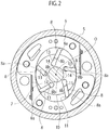
- the compression mechanism 2 is a concentric rotor type compression unit, and includes, as its main components, a cylinder block 6, a rotor 7, vanes 8, a pair of side blocks 9, and a drive shaft 10.
- the cylinder block 6 includes a cylinder chamber 12 that has an ellipsoidal-shaped smooth inner wall surface 11.
- the rotor 7 is rotatably provided at a center of the cylinder chamber 12.
- the rotor 7 formed are five vane slots 13 each of which is offset by a distance L from a radial line passing over a rotational center O of the rotor 7.
- the vanes 8 are slidably accommodated in the vane slots 13, respectively.
- the vane slots 13 are provided so as to be offset parallel on a reverse rotation side B opposite to a normal rotation side A of the rotor 7. Due to this offset, efficiency for compressing refrigerant can be improved.
- backpressure spaces 14 into which lubrication oil is introduced are formed between bottoms of the vane slots 13 and after-explained base edges 8b of the vanes 8.
- Each vane 8 is accommodated in each vane slot 13 and is protruded due to a rotation of the rotor, so that its end edge 8a slidably contacts with the inner wall surface 11 to compress refrigerant.
- the pair of side blocks 9 (see Fig. 1 ) is arranged so as to sandwich the cylinder block 6, and engaged with the cylinder block 6 by bolts or the like.
- the rotary shaft 10 is provided so as to penetrate the center of the rotor 7, and rotated by the electric motor 3 to transfer this rotational force to the rotor 7.
- the controller 15, the inverter 4, the electrical motor 3 and the compression mechanism 2 are connected with each other.
- the electrical motor 3 is controlled by the controller 15 via the inverter 4.
- the compressor 1 is used in an air conditioning system, and the controller 15 is connected with an external A/C amplifier (air conditioning amplifier).
- step S1 it is judged whether or not an air conditioner is activated (step S1), and then, when an activation command of the compressor 1 is generated (Yes in step S1), it is judged whether or not the vane(s) 8 accommodated in the vane slot(s) 13 protrudes form the vane slot(s) 13 (step S2).
- the vane 8 located at an upper position may be accommodated in the vane slot 13 due to its own weight (see Figs. 3(a) to (c) ).
- the rotor 7 is normally rotated to compress refrigerant (step S3).
- step S4 when the vane(s) 8 doesn't protrude from the vane slot(s) 13 (No in step S2), the rotor 7 is reversely rotated (step S4). Subsequently, it is judged whether or not a predetermined time for the reverse rotation of the rotor 7 has elapsed (step S5). When the predetermined time has not elapsed (No in step S5), the process flow is returned to step S4 to continue the reverse rotation. On the other hand, when the predetermined time has elapsed (Yes in step S5), the reverse rotation is stopped (step S6) and then the rotor 7 is normally rotated (step S3). Then, it is judged whether or not the air conditioner is stopped (step S7), the process flow ends when the air conditioner is stopped (Yes in step S7).
- the rotor 7 is reversely rotated when the vane(s) 8 doesn't protrude from the vane slot(s) 13.
- a frictional force and a viscous force of lubrication oil occur between the vanes 8 and the side blocks 9 due to the reverse rotation of the rotor 7.
- a tangential force f1 to the rotation applies to the vane(s) 8 as shown in Fig. 3(c) .
- a component force vector f2 of a force vector f1 applies to the vane(s) 8 as a force for protruding the vane (s) 8 from the vane slot (s) 13.
- the controller 15 reversely rotates the rotor 7 at slower speed than its normal rotational speed (normal rotational speed at a steady operation), so that the vanes 8 can be protruded from the vane slots 13 more surely. Namely, by reversely rotating the rotor 7 at lower speed than its normal rotational speed, secured can be a sufficient time for generating the backpressure in the backpressure spaces 14 and introducing lubrication oil and refrigerant into the backpressure spaces 14 through the clearances.
- the controller 15 controls the electrical motor 3 as a drive source of the compression mechanism 2 to normally/reversely rotate the rotor 7.
- the controller 15 controls a gear mechanism 31 to normally/reversely rotate the rotor 7.
- the gear mechanism 31 includes a normal rotation rotary shaft 32 and a reverse rotation rotary shaft 33 that are rotated by a rotational drive force form a drive source 30, a normal rotation gear set 34 provided on the normal rotation rotary shaft 32, and a reverse rotation gear set 35 provided on the reverse rotation rotary shaft 33.
- the normal rotation gear set 34 has a normal rotation first gear 34a and a normal rotation second gear 34b, and coupled with the compression mechanism 2 via these gears 34a and 34b.
- the reverse rotation gear set 35 has a reverse rotation first gear 35a, a reverse rotation second gear 35b and a reverse rotation third gear 35c, and coupled with the compression mechanism 2 via these gears 35a to 35c.
- the controller 15 judges, upon activating the air conditioner, whether or not the vane(s) 8 protrudes form the vane slot(s) 13.
- the vane(s) 8 doesn't protrude form the vane slot(s) 13
- the rotor 7 in the compression mechanism 2 is reversely rotated via the reverse rotation first to third gears 35a to 35c of the reverse rotation gear set 35.
- the normal rotation first and second gears 34a and 34b are used. According to this, one with a simple mechanism can be used as the drive source 30 (if the drive source 30 is a motor, a motor that rotates only normally can be used).
- Advantages by the reverse rotation of the rotor 7 are the same as those in the above-explained first embodiment.
Landscapes
- Engineering & Computer Science (AREA)
- Mechanical Engineering (AREA)
- General Engineering & Computer Science (AREA)
- Applications Or Details Of Rotary Compressors (AREA)
- Rotary Pumps (AREA)
- Control Of Positive-Displacement Pumps (AREA)
Claims (4)
- Rotationsflügel-Kompressor (1), der umfasst:eine Zylinder-Kammer (12), die eine elliptische Innenwandform hat;einen Rotor (7), der drehbar in der Zylinder-Kammer (12) angeordnet ist;einen Flügel (8), der in dem Rotor (7) so gehalten wird, dass er bei einer Drehung des Rotors (7) mit einer Innenwandfläche (11) der Zylinder-Kammer (12) in Kontakt kommt;einen Flügel-Schlitz (13), der sich an dem Rotor (7) befindet und an einer Umkehrdrehungs-Seite (B) des Rotors (7) gegenüber einer radialen Linie versetzt ist, die über einen Dreh-Mittelpunkt (O) des Rotors (7) verläuft; sowieeine Steuereinrichtung (15) zum Steuern einer Drehung des Rotors (7),dadurch gekennzeichnet, dassdie Steuereinrichtung (15) den Rotor (7) bei stationärem Betrieb über eine vorgegebene Zeit nach Aktivieren des Kompressors (1) mit einer niedrigeren Geschwindigkeit als einer normalen Drehgeschwindigkeit umgekehrt dreht.
- Kompressor (1) nach Anspruch 1, wobei die Steuereinrichtung (15) den Rotor (7) mit 10 U/min oder weniger umgekehrt dreht.
- Kompressor (1) nach Anspruch 1 oder 2, der des Weiteren umfasst:einen Elektromotor (3) als eine Antriebsquelle zum Drehen des Rotors (7), wobeidie Steuereinrichtung (15) den Rotor (7) umgekehrt dreht, indem sie eine Drehrichtung des Elektromotors (3) steuert.
- Kompressor (1) nach Anspruch 1 oder 2, der des Weiteren umfasst:eine Antriebsquelle (30) zum Drehen des Rotors (7); undeinen Getriebemechanismus (31), der sich zwischen der Antriebsquelle (30) und dem Rotor (7) befindet und eine Drehrichtung einer von der Antriebsquelle (30) auf den Rotor (7) übertragenen Drehkraft umschaltet, wobeidie Steuereinrichtung (15) den Rotor (7) umgekehrt dreht, indem sie den Getriebemechanismus (31) steuert.
Applications Claiming Priority (2)
| Application Number | Priority Date | Filing Date | Title |
|---|---|---|---|
| JP2009258984A JP5589358B2 (ja) | 2009-11-12 | 2009-11-12 | コンプレッサ |
| PCT/JP2010/068146 WO2011058848A1 (ja) | 2009-11-12 | 2010-10-15 | ベーン型ロータリコンプレッサ |
Publications (3)
| Publication Number | Publication Date |
|---|---|
| EP2500571A1 EP2500571A1 (de) | 2012-09-19 |
| EP2500571A4 EP2500571A4 (de) | 2016-03-23 |
| EP2500571B1 true EP2500571B1 (de) | 2018-03-28 |
Family
ID=43991508
Family Applications (1)
| Application Number | Title | Priority Date | Filing Date |
|---|---|---|---|
| EP10829808.4A Not-in-force EP2500571B1 (de) | 2009-11-12 | 2010-10-15 | Flügelzellenverdichter |
Country Status (5)
| Country | Link |
|---|---|
| US (1) | US9033675B2 (de) |
| EP (1) | EP2500571B1 (de) |
| JP (1) | JP5589358B2 (de) |
| CN (1) | CN102612600A (de) |
| WO (1) | WO2011058848A1 (de) |
Families Citing this family (6)
| Publication number | Priority date | Publication date | Assignee | Title |
|---|---|---|---|---|
| EP2542761A4 (de) * | 2010-03-01 | 2014-10-15 | Bright Energy Storage Technologies Llp | Drehkompressor-expander-systeme sowie entsprechende verfahren zu ihrer herstellung und verwendung |
| JP5421177B2 (ja) * | 2010-04-01 | 2014-02-19 | カルソニックカンセイ株式会社 | 電動気体圧縮機 |
| CA2839949A1 (en) | 2011-06-28 | 2013-01-03 | Bright Energy Storage Technologies, Llp | Semi-isothermal compression engines with separate combustors and expanders, and associated systems and methods |
| JP5589975B2 (ja) * | 2011-06-28 | 2014-09-17 | カルソニックカンセイ株式会社 | ベーン型圧縮機 |
| JP5919105B2 (ja) * | 2012-06-11 | 2016-05-18 | カルソニックカンセイ株式会社 | 電動ベーン型圧縮機 |
| WO2016078675A2 (en) * | 2014-11-18 | 2016-05-26 | Elzeiny Salah Elzeiny Mostafa | Electric power generation inside the water static animated |
Family Cites Families (16)
| Publication number | Priority date | Publication date | Assignee | Title |
|---|---|---|---|---|
| US3421413A (en) * | 1966-04-18 | 1969-01-14 | Abex Corp | Rotary vane fluid power unit |
| JPS575592A (en) * | 1980-06-12 | 1982-01-12 | Daikin Ind Ltd | Multivane compressor |
| JP2820463B2 (ja) * | 1989-11-02 | 1998-11-05 | 松下電器産業株式会社 | スクロール圧縮機の始動方法 |
| JPH08538Y2 (ja) | 1990-03-24 | 1996-01-10 | 光洋精工株式会社 | ベーンポンプ |
| JPH08538A (ja) | 1994-06-17 | 1996-01-09 | Fuji Photo Optical Co Ltd | 内視鏡内線状部材の保護構造 |
| US7290990B2 (en) * | 1998-06-05 | 2007-11-06 | Carrier Corporation | Short reverse rotation of compressor at startup |
| US6354821B1 (en) * | 2000-11-22 | 2002-03-12 | Scroll Technologies | Scroll compressor with dual clutch capacity modulation |
| JP3792578B2 (ja) * | 2001-02-28 | 2006-07-05 | カルソニックコンプレッサー株式会社 | 気体圧縮機 |
| JP4158348B2 (ja) * | 2001-03-23 | 2008-10-01 | 株式会社デンソー | 燃料噴射弁および燃料噴射弁の組み付け方法 |
| JP2002285983A (ja) | 2001-03-26 | 2002-10-03 | Seiko Instruments Inc | 気体圧縮機 |
| JP4061172B2 (ja) * | 2001-11-30 | 2008-03-12 | カルソニックコンプレッサー株式会社 | 気体圧縮機 |
| US6913451B2 (en) * | 2002-10-11 | 2005-07-05 | Innovative Solutions & Support Inc. | Vacuum pump with fail-safe vanes |
| GB0300183D0 (en) * | 2003-01-06 | 2003-02-05 | Waterworth Anthony | Feed and scavenge pump arrangement |
| JP4234480B2 (ja) | 2003-04-03 | 2009-03-04 | カルソニックコンプレッサー株式会社 | 電動気体圧縮機の制御装置 |
| JP4333238B2 (ja) * | 2003-07-10 | 2009-09-16 | パナソニック株式会社 | 圧縮機 |
| CN1954150A (zh) * | 2004-08-02 | 2007-04-25 | 松下电器产业株式会社 | 叶片旋转式空气泵 |
-
2009
- 2009-11-12 JP JP2009258984A patent/JP5589358B2/ja not_active Expired - Fee Related
-
2010
- 2010-10-15 WO PCT/JP2010/068146 patent/WO2011058848A1/ja not_active Ceased
- 2010-10-15 US US13/505,864 patent/US9033675B2/en not_active Expired - Fee Related
- 2010-10-15 EP EP10829808.4A patent/EP2500571B1/de not_active Not-in-force
- 2010-10-15 CN CN2010800513106A patent/CN102612600A/zh active Pending
Also Published As
| Publication number | Publication date |
|---|---|
| EP2500571A1 (de) | 2012-09-19 |
| CN102612600A (zh) | 2012-07-25 |
| JP5589358B2 (ja) | 2014-09-17 |
| JP2011106278A (ja) | 2011-06-02 |
| WO2011058848A1 (ja) | 2011-05-19 |
| US20120224986A1 (en) | 2012-09-06 |
| EP2500571A4 (de) | 2016-03-23 |
| WO2011058848A9 (ja) | 2012-02-16 |
| US9033675B2 (en) | 2015-05-19 |
Similar Documents
| Publication | Publication Date | Title |
|---|---|---|
| EP2500571B1 (de) | Flügelzellenverdichter | |
| CN113279958B (zh) | 涡旋式压缩机 | |
| JP5901446B2 (ja) | 回転型圧縮機 | |
| CN100564882C (zh) | 可变容量旋转压缩机 | |
| CN113994098B (zh) | 涡旋式压缩机 | |
| JP6738170B2 (ja) | スクロール圧縮機 | |
| JP4947174B2 (ja) | シングルスクリュー圧縮機 | |
| GB2452379A (en) | Scroll compressor back pressure chamber defined between seals on spaced planes | |
| JP2004293552A (ja) | 容量可変回転圧縮機 | |
| JP4516120B2 (ja) | 容量可変型ロータリ圧縮機及びその運転方法 | |
| WO2008023962A1 (en) | Variable capacity type rotary compressor | |
| KR20100014104A (ko) | 바이패스 포트들을 포함하는 스크롤 압축기용 라인 공급식 영구자석 동기 모터 | |
| JP4107903B2 (ja) | スクロール圧縮機 | |
| CN101506527A (zh) | 可变容量式旋转式压缩机 | |
| CN213743965U (zh) | 一种新能源汽车空调用一体式电动涡旋压缩机总成 | |
| KR200381834Y1 (ko) | 로터리 압축기의 용량 가변 장치 | |
| JP4151996B2 (ja) | スクロール型圧縮機 | |
| US20240011487A1 (en) | Scroll fluid machine | |
| CN208252345U (zh) | 机电双驱动单动盘涡旋压缩机 | |
| EP2375076B1 (de) | Drehzahlregelung für einen Spiralverdichter | |
| CN114017324A (zh) | 压缩机以及空调 | |
| KR100585810B1 (ko) | 이중 셀을 구비한 용량 가변형 로터리 압축기 및 그 운전방법 | |
| CN214464886U (zh) | 涡旋压缩膨胀一体机 | |
| JP4234480B2 (ja) | 電動気体圧縮機の制御装置 | |
| CN113614378A (zh) | 涡旋压缩机 |
Legal Events
| Date | Code | Title | Description |
|---|---|---|---|
| PUAI | Public reference made under article 153(3) epc to a published international application that has entered the european phase |
Free format text: ORIGINAL CODE: 0009012 |
|
| 17P | Request for examination filed |
Effective date: 20120612 |
|
| AK | Designated contracting states |
Kind code of ref document: A1 Designated state(s): AL AT BE BG CH CY CZ DE DK EE ES FI FR GB GR HR HU IE IS IT LI LT LU LV MC MK MT NL NO PL PT RO RS SE SI SK SM TR |
|
| DAX | Request for extension of the european patent (deleted) | ||
| RA4 | Supplementary search report drawn up and despatched (corrected) |
Effective date: 20160223 |
|
| RIC1 | Information provided on ipc code assigned before grant |
Ipc: F04C 28/06 20060101ALI20160217BHEP Ipc: F04C 28/08 20060101ALI20160217BHEP Ipc: F04C 29/06 20060101ALI20160217BHEP Ipc: F04B 49/06 20060101ALI20160217BHEP Ipc: F04C 28/04 20060101ALI20160217BHEP Ipc: F04C 18/344 20060101AFI20160217BHEP |
|
| RIC1 | Information provided on ipc code assigned before grant |
Ipc: F04C 28/08 20060101ALI20161115BHEP Ipc: F04C 28/06 20060101ALI20161115BHEP Ipc: F04C 18/344 20060101AFI20161115BHEP Ipc: F04B 49/06 20060101ALI20161115BHEP Ipc: F01C 21/08 20060101ALI20161115BHEP Ipc: F04C 29/06 20060101ALI20161115BHEP Ipc: F04C 28/04 20060101ALI20161115BHEP |
|
| GRAP | Despatch of communication of intention to grant a patent |
Free format text: ORIGINAL CODE: EPIDOSNIGR1 |
|
| INTG | Intention to grant announced |
Effective date: 20170104 |
|
| GRAJ | Information related to disapproval of communication of intention to grant by the applicant or resumption of examination proceedings by the epo deleted |
Free format text: ORIGINAL CODE: EPIDOSDIGR1 |
|
| INTC | Intention to grant announced (deleted) | ||
| 17Q | First examination report despatched |
Effective date: 20170526 |
|
| GRAP | Despatch of communication of intention to grant a patent |
Free format text: ORIGINAL CODE: EPIDOSNIGR1 |
|
| INTG | Intention to grant announced |
Effective date: 20171009 |
|
| GRAS | Grant fee paid |
Free format text: ORIGINAL CODE: EPIDOSNIGR3 |
|
| GRAA | (expected) grant |
Free format text: ORIGINAL CODE: 0009210 |
|
| STAA | Information on the status of an ep patent application or granted ep patent |
Free format text: STATUS: THE PATENT HAS BEEN GRANTED |
|
| AK | Designated contracting states |
Kind code of ref document: B1 Designated state(s): AL AT BE BG CH CY CZ DE DK EE ES FI FR GB GR HR HU IE IS IT LI LT LU LV MC MK MT NL NO PL PT RO RS SE SI SK SM TR |
|
| REG | Reference to a national code |
Ref country code: GB Ref legal event code: FG4D |
|
| REG | Reference to a national code |
Ref country code: CH Ref legal event code: EP |
|
| REG | Reference to a national code |
Ref country code: AT Ref legal event code: REF Ref document number: 983703 Country of ref document: AT Kind code of ref document: T Effective date: 20180415 |
|
| REG | Reference to a national code |
Ref country code: IE Ref legal event code: FG4D |
|
| REG | Reference to a national code |
Ref country code: DE Ref legal event code: R096 Ref document number: 602010049551 Country of ref document: DE |
|
| PG25 | Lapsed in a contracting state [announced via postgrant information from national office to epo] |
Ref country code: LT Free format text: LAPSE BECAUSE OF FAILURE TO SUBMIT A TRANSLATION OF THE DESCRIPTION OR TO PAY THE FEE WITHIN THE PRESCRIBED TIME-LIMIT Effective date: 20180328 Ref country code: NO Free format text: LAPSE BECAUSE OF FAILURE TO SUBMIT A TRANSLATION OF THE DESCRIPTION OR TO PAY THE FEE WITHIN THE PRESCRIBED TIME-LIMIT Effective date: 20180628 Ref country code: HR Free format text: LAPSE BECAUSE OF FAILURE TO SUBMIT A TRANSLATION OF THE DESCRIPTION OR TO PAY THE FEE WITHIN THE PRESCRIBED TIME-LIMIT Effective date: 20180328 Ref country code: FI Free format text: LAPSE BECAUSE OF FAILURE TO SUBMIT A TRANSLATION OF THE DESCRIPTION OR TO PAY THE FEE WITHIN THE PRESCRIBED TIME-LIMIT Effective date: 20180328 |
|
| REG | Reference to a national code |
Ref country code: NL Ref legal event code: MP Effective date: 20180328 |
|
| REG | Reference to a national code |
Ref country code: LT Ref legal event code: MG4D |
|
| PG25 | Lapsed in a contracting state [announced via postgrant information from national office to epo] |
Ref country code: SE Free format text: LAPSE BECAUSE OF FAILURE TO SUBMIT A TRANSLATION OF THE DESCRIPTION OR TO PAY THE FEE WITHIN THE PRESCRIBED TIME-LIMIT Effective date: 20180328 Ref country code: LV Free format text: LAPSE BECAUSE OF FAILURE TO SUBMIT A TRANSLATION OF THE DESCRIPTION OR TO PAY THE FEE WITHIN THE PRESCRIBED TIME-LIMIT Effective date: 20180328 Ref country code: GR Free format text: LAPSE BECAUSE OF FAILURE TO SUBMIT A TRANSLATION OF THE DESCRIPTION OR TO PAY THE FEE WITHIN THE PRESCRIBED TIME-LIMIT Effective date: 20180629 Ref country code: BG Free format text: LAPSE BECAUSE OF FAILURE TO SUBMIT A TRANSLATION OF THE DESCRIPTION OR TO PAY THE FEE WITHIN THE PRESCRIBED TIME-LIMIT Effective date: 20180628 Ref country code: RS Free format text: LAPSE BECAUSE OF FAILURE TO SUBMIT A TRANSLATION OF THE DESCRIPTION OR TO PAY THE FEE WITHIN THE PRESCRIBED TIME-LIMIT Effective date: 20180328 |
|
| PG25 | Lapsed in a contracting state [announced via postgrant information from national office to epo] |
Ref country code: IT Free format text: LAPSE BECAUSE OF FAILURE TO SUBMIT A TRANSLATION OF THE DESCRIPTION OR TO PAY THE FEE WITHIN THE PRESCRIBED TIME-LIMIT Effective date: 20180328 Ref country code: AL Free format text: LAPSE BECAUSE OF FAILURE TO SUBMIT A TRANSLATION OF THE DESCRIPTION OR TO PAY THE FEE WITHIN THE PRESCRIBED TIME-LIMIT Effective date: 20180328 Ref country code: EE Free format text: LAPSE BECAUSE OF FAILURE TO SUBMIT A TRANSLATION OF THE DESCRIPTION OR TO PAY THE FEE WITHIN THE PRESCRIBED TIME-LIMIT Effective date: 20180328 Ref country code: PL Free format text: LAPSE BECAUSE OF FAILURE TO SUBMIT A TRANSLATION OF THE DESCRIPTION OR TO PAY THE FEE WITHIN THE PRESCRIBED TIME-LIMIT Effective date: 20180328 Ref country code: RO Free format text: LAPSE BECAUSE OF FAILURE TO SUBMIT A TRANSLATION OF THE DESCRIPTION OR TO PAY THE FEE WITHIN THE PRESCRIBED TIME-LIMIT Effective date: 20180328 Ref country code: ES Free format text: LAPSE BECAUSE OF FAILURE TO SUBMIT A TRANSLATION OF THE DESCRIPTION OR TO PAY THE FEE WITHIN THE PRESCRIBED TIME-LIMIT Effective date: 20180328 Ref country code: NL Free format text: LAPSE BECAUSE OF FAILURE TO SUBMIT A TRANSLATION OF THE DESCRIPTION OR TO PAY THE FEE WITHIN THE PRESCRIBED TIME-LIMIT Effective date: 20180328 |
|
| PG25 | Lapsed in a contracting state [announced via postgrant information from national office to epo] |
Ref country code: SM Free format text: LAPSE BECAUSE OF FAILURE TO SUBMIT A TRANSLATION OF THE DESCRIPTION OR TO PAY THE FEE WITHIN THE PRESCRIBED TIME-LIMIT Effective date: 20180328 Ref country code: CZ Free format text: LAPSE BECAUSE OF FAILURE TO SUBMIT A TRANSLATION OF THE DESCRIPTION OR TO PAY THE FEE WITHIN THE PRESCRIBED TIME-LIMIT Effective date: 20180328 Ref country code: SK Free format text: LAPSE BECAUSE OF FAILURE TO SUBMIT A TRANSLATION OF THE DESCRIPTION OR TO PAY THE FEE WITHIN THE PRESCRIBED TIME-LIMIT Effective date: 20180328 |
|
| REG | Reference to a national code |
Ref country code: AT Ref legal event code: MK05 Ref document number: 983703 Country of ref document: AT Kind code of ref document: T Effective date: 20180328 |
|
| PG25 | Lapsed in a contracting state [announced via postgrant information from national office to epo] |
Ref country code: PT Free format text: LAPSE BECAUSE OF FAILURE TO SUBMIT A TRANSLATION OF THE DESCRIPTION OR TO PAY THE FEE WITHIN THE PRESCRIBED TIME-LIMIT Effective date: 20180730 |
|
| REG | Reference to a national code |
Ref country code: DE Ref legal event code: R097 Ref document number: 602010049551 Country of ref document: DE |
|
| PG25 | Lapsed in a contracting state [announced via postgrant information from national office to epo] |
Ref country code: AT Free format text: LAPSE BECAUSE OF FAILURE TO SUBMIT A TRANSLATION OF THE DESCRIPTION OR TO PAY THE FEE WITHIN THE PRESCRIBED TIME-LIMIT Effective date: 20180328 Ref country code: DK Free format text: LAPSE BECAUSE OF FAILURE TO SUBMIT A TRANSLATION OF THE DESCRIPTION OR TO PAY THE FEE WITHIN THE PRESCRIBED TIME-LIMIT Effective date: 20180328 |
|
| PLBE | No opposition filed within time limit |
Free format text: ORIGINAL CODE: 0009261 |
|
| STAA | Information on the status of an ep patent application or granted ep patent |
Free format text: STATUS: NO OPPOSITION FILED WITHIN TIME LIMIT |
|
| 26N | No opposition filed |
Effective date: 20190103 |
|
| REG | Reference to a national code |
Ref country code: DE Ref legal event code: R119 Ref document number: 602010049551 Country of ref document: DE |
|
| PG25 | Lapsed in a contracting state [announced via postgrant information from national office to epo] |
Ref country code: SI Free format text: LAPSE BECAUSE OF FAILURE TO SUBMIT A TRANSLATION OF THE DESCRIPTION OR TO PAY THE FEE WITHIN THE PRESCRIBED TIME-LIMIT Effective date: 20180328 |
|
| REG | Reference to a national code |
Ref country code: CH Ref legal event code: PL |
|
| GBPC | Gb: european patent ceased through non-payment of renewal fee |
Effective date: 20181015 |
|
| REG | Reference to a national code |
Ref country code: BE Ref legal event code: MM Effective date: 20181031 |
|
| PG25 | Lapsed in a contracting state [announced via postgrant information from national office to epo] |
Ref country code: LU Free format text: LAPSE BECAUSE OF NON-PAYMENT OF DUE FEES Effective date: 20181015 Ref country code: MC Free format text: LAPSE BECAUSE OF FAILURE TO SUBMIT A TRANSLATION OF THE DESCRIPTION OR TO PAY THE FEE WITHIN THE PRESCRIBED TIME-LIMIT Effective date: 20180328 |
|
| REG | Reference to a national code |
Ref country code: IE Ref legal event code: MM4A |
|
| PG25 | Lapsed in a contracting state [announced via postgrant information from national office to epo] |
Ref country code: DE Free format text: LAPSE BECAUSE OF NON-PAYMENT OF DUE FEES Effective date: 20190501 |
|
| PG25 | Lapsed in a contracting state [announced via postgrant information from national office to epo] |
Ref country code: CH Free format text: LAPSE BECAUSE OF NON-PAYMENT OF DUE FEES Effective date: 20181031 Ref country code: LI Free format text: LAPSE BECAUSE OF NON-PAYMENT OF DUE FEES Effective date: 20181031 Ref country code: FR Free format text: LAPSE BECAUSE OF NON-PAYMENT OF DUE FEES Effective date: 20181031 Ref country code: BE Free format text: LAPSE BECAUSE OF NON-PAYMENT OF DUE FEES Effective date: 20181031 |
|
| PG25 | Lapsed in a contracting state [announced via postgrant information from national office to epo] |
Ref country code: GB Free format text: LAPSE BECAUSE OF NON-PAYMENT OF DUE FEES Effective date: 20181015 Ref country code: IE Free format text: LAPSE BECAUSE OF NON-PAYMENT OF DUE FEES Effective date: 20181015 |
|
| PG25 | Lapsed in a contracting state [announced via postgrant information from national office to epo] |
Ref country code: MT Free format text: LAPSE BECAUSE OF NON-PAYMENT OF DUE FEES Effective date: 20181015 |
|
| PG25 | Lapsed in a contracting state [announced via postgrant information from national office to epo] |
Ref country code: TR Free format text: LAPSE BECAUSE OF FAILURE TO SUBMIT A TRANSLATION OF THE DESCRIPTION OR TO PAY THE FEE WITHIN THE PRESCRIBED TIME-LIMIT Effective date: 20180328 |
|
| PG25 | Lapsed in a contracting state [announced via postgrant information from national office to epo] |
Ref country code: CY Free format text: LAPSE BECAUSE OF FAILURE TO SUBMIT A TRANSLATION OF THE DESCRIPTION OR TO PAY THE FEE WITHIN THE PRESCRIBED TIME-LIMIT Effective date: 20180328 Ref country code: HU Free format text: LAPSE BECAUSE OF FAILURE TO SUBMIT A TRANSLATION OF THE DESCRIPTION OR TO PAY THE FEE WITHIN THE PRESCRIBED TIME-LIMIT; INVALID AB INITIO Effective date: 20101015 Ref country code: MK Free format text: LAPSE BECAUSE OF NON-PAYMENT OF DUE FEES Effective date: 20180328 |
|
| PG25 | Lapsed in a contracting state [announced via postgrant information from national office to epo] |
Ref country code: IS Free format text: LAPSE BECAUSE OF FAILURE TO SUBMIT A TRANSLATION OF THE DESCRIPTION OR TO PAY THE FEE WITHIN THE PRESCRIBED TIME-LIMIT Effective date: 20180728 |