EP2500585B1 - Élément de rétention pour verrou à cliquet entre un boîtier et un élément de couverture d'ouverture de boîtier - Google Patents
Élément de rétention pour verrou à cliquet entre un boîtier et un élément de couverture d'ouverture de boîtier Download PDFInfo
- Publication number
- EP2500585B1 EP2500585B1 EP11165694.8A EP11165694A EP2500585B1 EP 2500585 B1 EP2500585 B1 EP 2500585B1 EP 11165694 A EP11165694 A EP 11165694A EP 2500585 B1 EP2500585 B1 EP 2500585B1
- Authority
- EP
- European Patent Office
- Prior art keywords
- leg
- housing
- detent
- legs
- arrangement according
- Prior art date
- Legal status (The legal status is an assumption and is not a legal conclusion. Google has not performed a legal analysis and makes no representation as to the accuracy of the status listed.)
- Not-in-force
Links
- 230000001747 exhibiting effect Effects 0.000 claims description 2
- 239000004744 fabric Substances 0.000 description 5
- 206010001497 Agitation Diseases 0.000 description 2
- 238000013019 agitation Methods 0.000 description 2
- 238000003780 insertion Methods 0.000 description 2
- 230000037431 insertion Effects 0.000 description 2
- 239000000463 material Substances 0.000 description 2
- 238000000034 method Methods 0.000 description 2
- 230000000903 blocking effect Effects 0.000 description 1
- 230000008878 coupling Effects 0.000 description 1
- 238000010168 coupling process Methods 0.000 description 1
- 238000005859 coupling reaction Methods 0.000 description 1
- 230000001419 dependent effect Effects 0.000 description 1
- 230000003993 interaction Effects 0.000 description 1
Images

Classifications
-
- F—MECHANICAL ENGINEERING; LIGHTING; HEATING; WEAPONS; BLASTING
- F16—ENGINEERING ELEMENTS AND UNITS; GENERAL MEASURES FOR PRODUCING AND MAINTAINING EFFECTIVE FUNCTIONING OF MACHINES OR INSTALLATIONS; THERMAL INSULATION IN GENERAL
- F16B—DEVICES FOR FASTENING OR SECURING CONSTRUCTIONAL ELEMENTS OR MACHINE PARTS TOGETHER, e.g. NAILS, BOLTS, CIRCLIPS, CLAMPS, CLIPS OR WEDGES; JOINTS OR JOINTING
- F16B21/00—Means for preventing relative axial movement of a pin, spigot, shaft or the like and a member surrounding it; Stud-and-socket releasable fastenings
- F16B21/06—Releasable fastening devices with snap-action
- F16B21/065—Releasable fastening devices with snap-action with an additional locking element
-
- F—MECHANICAL ENGINEERING; LIGHTING; HEATING; WEAPONS; BLASTING
- F16—ENGINEERING ELEMENTS AND UNITS; GENERAL MEASURES FOR PRODUCING AND MAINTAINING EFFECTIVE FUNCTIONING OF MACHINES OR INSTALLATIONS; THERMAL INSULATION IN GENERAL
- F16B—DEVICES FOR FASTENING OR SECURING CONSTRUCTIONAL ELEMENTS OR MACHINE PARTS TOGETHER, e.g. NAILS, BOLTS, CIRCLIPS, CLAMPS, CLIPS OR WEDGES; JOINTS OR JOINTING
- F16B5/00—Joining sheets or plates, e.g. panels, to one another or to strips or bars parallel to them
- F16B5/06—Joining sheets or plates, e.g. panels, to one another or to strips or bars parallel to them by means of clamps or clips
- F16B5/0607—Joining sheets or plates, e.g. panels, to one another or to strips or bars parallel to them by means of clamps or clips joining sheets or plates to each other
- F16B5/0621—Joining sheets or plates, e.g. panels, to one another or to strips or bars parallel to them by means of clamps or clips joining sheets or plates to each other in parallel relationship
- F16B5/0664—Joining sheets or plates, e.g. panels, to one another or to strips or bars parallel to them by means of clamps or clips joining sheets or plates to each other in parallel relationship at least one of the sheets or plates having integrally formed or integrally connected snap-in-features
Definitions
- the invention refers to an arrangement comprising a housing, a covering element of a housing aperture and a detent lock between the housing and the covering element.
- Detent locks known in the art e.g. detent locks of a covering element of a housing, are not additionally secured.
- US 4,180,247 discloses a method and device for attaching chain link fabric to the framework of fences and other such enclosures.
- a method and device for holding chain link fabric to the outside face or surface of said framework is disclosed.
- the framework (end post, line post, top rail, and/or bottom rail) is provided with a plurality of slots in the sides of the members of the framework, into which special clips or retainers mesh by press-fit and hold the chain link fabric in place.
- the said clips or retainers being capable of providing a tight connection to maintain the interface between the chain link fabric and the framework member to which attached one tension on the chain link fabric to keep it taut has been established.
- Several types of clips are provided that may be used. The system is useable on a variety of framework member cross-sectional designs.
- GB 2209368 A discloses a single-fin fastener comprising: a base member; a support board projecting from said base member; an engaging fin having a flexible hinging butt at a tip of said support board, said engaging fin extending from said flexible hinging butt in a direction reverse to that of the projection of said support board, said engaging fin including an engaging notched portion and a stopper extending from said engaging notched portion to the movable tip of said fin; opening preventing means for preventing said stopper from further opening, said opening preventing means being provided continuously to said base member and facing said stopper through a gap.
- the objective is achieved by an arrangement comprising a housing, a covering element of a housing aperture and a detent lock between the housing and the covering element, the detent lock comprising a retaining element, wherein a detent element of the detent lock exhibits an essentially U-shaped cross section formed by two resiliently coupled legs, wherein the retaining element may be positively and/or non-positively locked in the area between the legs of the detent element and wherein the retaining element comprises a respective recess on two sides, wherein in each recess a lateral housing section may be positively and/or non-positively locked.
- the legs Due to the arrangement of the retaining element between the two legs of the detent element the legs are prevented from moving towards each other. Consequently, the detent lock with the arranged retaining element is prevented from being accidentally released, e.g. by vibration, centrifugal forces or other agitations.
- a particular advantage is that the loss of the covering element of the housing aperture resulting from release of the detent lock is prevented.
- the retaining element has two symmetrically arranged legs which are resiliently coupled to each other in a lower, rounded section, wherein the recesses are formed on outer faces of the legs corresponding to a wall thickness of the housing in the region of the lateral housing section.
- End sections of the legs may be widened with respect to the remaining leg.
- the end sections may have a surface structure on the outer face such as a surface wrinkling or a corrugation, thus increasing the grip and facilitating handling of the retaining element.
- the lower, rounded section and adjacent lower regions of the legs may be shaped corresponding to the gap between the first leg and the second leg of the detent element.
- the legs may be arranged to be moved towards each other by application of a force to the end sections.
- the retaining element is applied to secure a detent lock between a housing and a covering element of a housing aperture
- the detent lock comprises a detent element exhibiting an essentially U-shaped cross section formed by two slewably or resiliently coupled legs, the detent element moulded in the covering element or integrally moulded with the covering element, wherein the detent element is arrangeable in a non-positively and/or positively locked manner in a rectangular clearance which extends the housing aperture.
- the retaining element is inserted into the space provided between the first leg and the second leg of the detent element in a non-positive and/or positive locking manner thus preventing relative motion of the legs towards each other.
- the shapes of the detent element and the rectangular clearance may correspond to each other.
- the first leg is moulded in the covering element or integrally moulded with the covering element in a manner resulting in a material engagement of the two parts or a one-piece arrangement.
- a latch may be formed at an outer face of the second leg pointing away from the first leg, wherein the latch may be arranged to engage in the region of a front face of the rectangular clearance beneath an edge, thus providing a releasable detent lock.
- the second leg may be moved towards the first leg in such a manner that the latch is no longer arranged beneath the edge thereby releasing the detent lock.
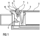
- Figure 1 is a schematic lateral view of a detent lock between a housing 1 and a covering element 2 of a housing aperture 3 with a retaining element 4.
- the housing 1 may be arranged as a conventional housing such as a housing of a remote control. At least one housing aperture 3 is arranged in the housing 1. The housing aperture 3 may be covered by the covering element 2 with positive locking.
- At least one detent lock between the covering element 2 and the housing 1 may be established for mechanically coupling the covering element 2 with the housing 1.
- a conventional detent element 5 is moulded in the covering element 2 or integrally moulded with the covering element 2, wherein the detent element 5 may be arranged in a non-positively and/or positively locked manner in a rectangular clearance 6 which extends the housing aperture 3.
- the shapes of the detent element 5 and the rectangular clearance 6 correspond to each other.
- the detent element 5 exhibits an essentially U-shaped cross section formed from a first leg 7 and a second leg 8 which are resiliently or slewably mounted to each other.
- the first leg 7 is preferably moulded in the covering element 2 or integrally moulded with the covering element 2 in a manner resulting in a material engagement of the two parts or a one-piece arrangement.
- a latch 10 is formed at the free end 9 of the second leg 8 .
- the latch 10 is arranged at an outer face of the second leg 8 pointing away from the first leg 7.
- the latch 10 is arranged on the second leg 8 in such a manner that the latch 10 may be arranged in the region of a front face 11 of the rectangular clearance 6 beneath an edge 12, thus providing a releasable detent lock.
- the second leg 8 may be moved towards the first leg 7 in such a manner that the latch 10 is no longer arranged beneath the edge 12 thereby releasing the detent lock.
- the retaining element 4 is inserted into the space provided between the first leg 7 and the second leg 8 of the detent element 5 in a non-positive and/or positive locking manner thus preventing relative motion of the legs 7 and 8 towards each other.
- Figure 2 shows a schematic front view of the detent lock between the housing 1 and the covering element 2 of a housing aperture 3 with the retaining element 4.
- FIG 3 is a schematic perspective view of the retaining element 4.
- the retaining element 4 comprises two symmetrically arranged legs 13 which are resiliently coupled to each other in a lower, rounded section 14. On the outer faces 15 of the legs 13 respective recesses 16 are formed corresponding to a wall thickness W of the housing 1 in the region of the rectangular clearance 6.
- the end sections 17 of the legs 13 may be widened with respect to the remaining leg 13.
- the end sections 17 may have a surface structure on the outer face 15, e.g. a surface wrinkling or a corrugation, thus increasing the grip and facilitating handling of the retaining element 4.
- the retaining element 4 is inserted into the gap in the detent element 5 between the first leg 7 and the second leg 8.
- the section 14 and the lower regions of the legs 13 are shaped corresponding to the gap between the first leg 7 and the second leg 8 of the detent element 5.
- the two legs 13 of the retaining element 4 are moved towards each other due to interaction of the lateral housing sections 18 of the rectangular clearance 6 until the recesses 16 are arranged in the region of the rectangular clearance 6.
- a respective detent lock is established, wherein the two legs 13 of the retaining element 4 move apart in such a manner that the lateral housing sections 18 of the rectangular clearance 6 are arranged in the recesses 16 of the retaining element 4 forming a non-positive and/or positive lock.
- the legs 13 may be moved towards each other by application of a force to the end sections 17, thus releasing the detent lock between the recesses 16 of the retaining element 4 and the lateral housing sections 18 of the rectangular clearance 6 is released and the retaining element 4 may be removed from the gap between the first leg 7 and the second leg 8 of the detent element 5.
- the legs 7 and 8 Due to the arrangement of the retaining element 4 between the two legs 7 and 8 of the detent element 5 the legs 7 and 8 are prevented from moving towards each other. Consequently, the detent lock with the arranged retaining element 4 is prevented from being accidentally released, e.g. by vibration, centrifugal forces or other agitations.
- a particular advantage is that the loss of the covering element 2 of the housing aperture 3 resulting from release of the detent lock is prevented.
Landscapes
- Engineering & Computer Science (AREA)
- General Engineering & Computer Science (AREA)
- Mechanical Engineering (AREA)
- Casings For Electric Apparatus (AREA)
Claims (8)
- Système comprenant un logement (1), un élément de couverture (2) d'une ouverture de logement (3) et un dispositif de blocage par arrêt entre le logement (1) et l'élément de couverture (2), le dispositif de blocage par arrêt comprenant un élément de retenue (4) et un élément d'arrêt (5) présentant une section transversale essentiellement en forme de U formée par deux branches (7, 8) accouplées de manière pivotante ou élastique et conçues pour se loger dans l'ouverture de logement (3), l'élément de retenue (4) étant formé et conçu pour être bloqué par accouplement géométrique et/ou accouplement par friction dans un espace entre les branches (7, 8) de l'élément d'arrêt (5) de telle sorte que les deux branches (7, 8) de l'élément d'arrêt (5) ne soient pas en mesure de se déplacer l'une vers l'autre, l'élément d'arrêt (5) étant moulé dans l'élément de couverture (2) ou étant moulé d'un seul tenant avec l'élément de couverture (2), l'élément d'arrêt (5) pouvant être disposé de façon à être bloqué par accouplement par friction et/ou accouplement géométrique dans un intervalle rectangulaire (6) qui prolonge l'ouverture de logement (3) et l'élément de retenue (4) comprenant un évidement respectif (16) sur deux côtés conçu pour permettre à une section de logement latérale (18) respective située à côté de l'ouverture de logement (3) de se bloquer par accouplement géométrique et/ou accouplement par friction sur l'élément de retenue (4), l'élément de retenue (4) comprenant deux branches (13) disposées symétriquement qui sont accouplées l'une avec l'autre de manière élastique au niveau d'une section inférieure arrondie (14), les évidements (16) étant formés sur des faces extérieures (15) des branches (13) correspondant à une épaisseur de paroi (W) du logement (1) dans la région de la section de logement latérale (18).
- Système selon la revendication 1, caractérisé en ce que des sections d'extrémité (17) des branches (13) sont élargies par rapport au reste de la branche (13).
- Système selon la revendication 2, caractérisé en ce que les sections d'extrémité (17) comportent une structure de surface sur la face extérieure (15).
- Système selon la revendication 3, caractérisé en ce que la structure de surface est un plissement de surface ou des ondulations.
- Système selon l'une des revendications 1 à 4, caractérisé en ce que la section inférieure arrondie (14) et les régions inférieures adjacentes des branches (13) présentent une forme correspondant à l'espace entre la première branche (7) et la seconde branche (8) de l'élément d'arrêt (5).
- Système selon l'une des revendications 1 à 5, caractérisé en ce que les branches (13) sont conçues pour être déplacées l'une vers l'autre par application d'une force aux sections d'extrémité (17).
- Système selon l'une des revendications 1 à 6, caractérisé en ce que les formes de l'élément d'arrêt (5) et de l'intervalle rectangulaire (6) se correspondent.
- Système selon l'une des revendications 1 à 7, caractérisé en ce que la première branche (7) est moulée dans l'élément de couverture (2) ou est moulée d'un seul tenant avec l'élément de couverture (2), un élément de verrouillage (10) étant formé, au niveau d'une extrémité libre (9) de la seconde branche (8), au niveau d'une face extérieure (15) de la seconde branche (8), dans une orientation s'éloignant de la première branche (7), l'élément de verrouillage (10) étant conçu pour se loger, dans la région d'une face avant (11) de l'intervalle rectangulaire (6), sous un bord (12), le dispositif de blocage par arrêt étant conçu pour être libéré par déplacement de la seconde branche (8) en direction de la première branche (7) de telle sorte que l'élément de verrouillage (10) ne soit plus disposé sous le bord (12).
Applications Claiming Priority (1)
| Application Number | Priority Date | Filing Date | Title |
|---|---|---|---|
| DE102011013971 | 2011-03-15 |
Publications (2)
| Publication Number | Publication Date |
|---|---|
| EP2500585A1 EP2500585A1 (fr) | 2012-09-19 |
| EP2500585B1 true EP2500585B1 (fr) | 2017-03-08 |
Family
ID=46052957
Family Applications (1)
| Application Number | Title | Priority Date | Filing Date |
|---|---|---|---|
| EP11165694.8A Not-in-force EP2500585B1 (fr) | 2011-03-15 | 2011-05-11 | Élément de rétention pour verrou à cliquet entre un boîtier et un élément de couverture d'ouverture de boîtier |
Country Status (1)
| Country | Link |
|---|---|
| EP (1) | EP2500585B1 (fr) |
Family Cites Families (3)
| Publication number | Priority date | Publication date | Assignee | Title |
|---|---|---|---|---|
| US4180247A (en) * | 1977-05-20 | 1979-12-25 | Anchor Post Products, Inc. | Chain link fabric attaching system |
| JPH0353041Y2 (fr) * | 1987-08-31 | 1991-11-19 | ||
| DE102007045296B3 (de) * | 2007-09-21 | 2008-12-11 | A. Raymond Et Cie | Vorrichtung zum Befestigen von zwei Anbauteilen an einem Trägerteil |
-
2011
- 2011-05-11 EP EP11165694.8A patent/EP2500585B1/fr not_active Not-in-force
Non-Patent Citations (1)
| Title |
|---|
| None * |
Also Published As
| Publication number | Publication date |
|---|---|
| EP2500585A1 (fr) | 2012-09-19 |
Similar Documents
| Publication | Publication Date | Title |
|---|---|---|
| US12273066B2 (en) | Device and method for aligning a solar panel with respect to a roof-mounted installation rail prior to installation | |
| US8944733B2 (en) | Device for holding an add-on part on a support part, and arrangement with a device of this type and with an add-on part | |
| ES2539606T3 (es) | Dispositivo de gestión de cables montado en armazón | |
| JP6543694B2 (ja) | 誘導装置 | |
| US9071007B2 (en) | Connector with grommet | |
| JP2010144900A (ja) | 固定具 | |
| KR20130004898A (ko) | 고정 장치 | |
| JP4989211B2 (ja) | 電気接続箱 | |
| US11311109B2 (en) | Reinforced bed frame | |
| CN101802419A (zh) | 将两个附件固定在一个支撑件上的装置 | |
| KR101683968B1 (ko) | 띠장 브래킷 | |
| KR101548326B1 (ko) | 새들 결합용 클립이 탄성 복원에 의하여 새들용 강재에 결합되는 건축 구조물의 지붕 구조 | |
| JP5839879B2 (ja) | 配管固定具、配管固定方法 | |
| KR101498224B1 (ko) | 와이퍼 블레이드 장치 | |
| JP6740745B2 (ja) | バンパホルダ | |
| JP5406078B2 (ja) | 簡易屋根の中骨の取付構造、及び、それを備える簡易屋根 | |
| KR101661589B1 (ko) | 안내판 걸이구 | |
| EP2500585A1 (fr) | Élément de rétention pour verrou à cliquet entre un boîtier et un élément de couverture d'ouverture de boîtier | |
| KR200490126Y1 (ko) | 케이블 트레이의 연결체 | |
| KR20090107741A (ko) | 간판용 프레임 | |
| JP2004166661A (ja) | ペットケージ | |
| KR100773836B1 (ko) | 박스의 커버장착구조 | |
| JP2011249221A (ja) | コネクタの取付構造 | |
| JP7208745B2 (ja) | ロック部材の取付構造及び取付方法 | |
| KR20190058424A (ko) | 금속 천장재 고정 시스템 및 이탈방지장치 |
Legal Events
| Date | Code | Title | Description |
|---|---|---|---|
| PUAI | Public reference made under article 153(3) epc to a published international application that has entered the european phase |
Free format text: ORIGINAL CODE: 0009012 |
|
| AK | Designated contracting states |
Kind code of ref document: A1 Designated state(s): AL AT BE BG CH CY CZ DE DK EE ES FI FR GB GR HR HU IE IS IT LI LT LU LV MC MK MT NL NO PL PT RO RS SE SI SK SM TR |
|
| AX | Request for extension of the european patent |
Extension state: BA ME |
|
| RIN1 | Information on inventor provided before grant (corrected) |
Inventor name: LANGER, PETER Inventor name: OHLER, JENS Inventor name: BIELETZKI-WELZ, VIKTOR Inventor name: NOEL, CHRISTIAN Inventor name: IVANOV, STOYAN Inventor name: KOLIMECHKOV, GEORGI |
|
| 17P | Request for examination filed |
Effective date: 20130319 |
|
| 17Q | First examination report despatched |
Effective date: 20151123 |
|
| GRAP | Despatch of communication of intention to grant a patent |
Free format text: ORIGINAL CODE: EPIDOSNIGR1 |
|
| INTG | Intention to grant announced |
Effective date: 20160927 |
|
| GRAS | Grant fee paid |
Free format text: ORIGINAL CODE: EPIDOSNIGR3 |
|
| GRAA | (expected) grant |
Free format text: ORIGINAL CODE: 0009210 |
|
| AK | Designated contracting states |
Kind code of ref document: B1 Designated state(s): AL AT BE BG CH CY CZ DE DK EE ES FI FR GB GR HR HU IE IS IT LI LT LU LV MC MK MT NL NO PL PT RO RS SE SI SK SM TR |
|
| REG | Reference to a national code |
Ref country code: GB Ref legal event code: FG4D |
|
| REG | Reference to a national code |
Ref country code: CH Ref legal event code: EP Ref country code: AT Ref legal event code: REF Ref document number: 873801 Country of ref document: AT Kind code of ref document: T Effective date: 20170315 |
|
| REG | Reference to a national code |
Ref country code: IE Ref legal event code: FG4D |
|
| REG | Reference to a national code |
Ref country code: DE Ref legal event code: R096 Ref document number: 602011035630 Country of ref document: DE |
|
| REG | Reference to a national code |
Ref country code: FR Ref legal event code: PLFP Year of fee payment: 7 |
|
| REG | Reference to a national code |
Ref country code: LT Ref legal event code: MG4D |
|
| REG | Reference to a national code |
Ref country code: NL Ref legal event code: MP Effective date: 20170308 |
|
| PG25 | Lapsed in a contracting state [announced via postgrant information from national office to epo] |
Ref country code: LT Free format text: LAPSE BECAUSE OF FAILURE TO SUBMIT A TRANSLATION OF THE DESCRIPTION OR TO PAY THE FEE WITHIN THE PRESCRIBED TIME-LIMIT Effective date: 20170308 Ref country code: NO Free format text: LAPSE BECAUSE OF FAILURE TO SUBMIT A TRANSLATION OF THE DESCRIPTION OR TO PAY THE FEE WITHIN THE PRESCRIBED TIME-LIMIT Effective date: 20170608 Ref country code: FI Free format text: LAPSE BECAUSE OF FAILURE TO SUBMIT A TRANSLATION OF THE DESCRIPTION OR TO PAY THE FEE WITHIN THE PRESCRIBED TIME-LIMIT Effective date: 20170308 Ref country code: HR Free format text: LAPSE BECAUSE OF FAILURE TO SUBMIT A TRANSLATION OF THE DESCRIPTION OR TO PAY THE FEE WITHIN THE PRESCRIBED TIME-LIMIT Effective date: 20170308 Ref country code: GR Free format text: LAPSE BECAUSE OF FAILURE TO SUBMIT A TRANSLATION OF THE DESCRIPTION OR TO PAY THE FEE WITHIN THE PRESCRIBED TIME-LIMIT Effective date: 20170609 |
|
| PGFP | Annual fee paid to national office [announced via postgrant information from national office to epo] |
Ref country code: FR Payment date: 20170523 Year of fee payment: 7 |
|
| REG | Reference to a national code |
Ref country code: AT Ref legal event code: MK05 Ref document number: 873801 Country of ref document: AT Kind code of ref document: T Effective date: 20170308 |
|
| PG25 | Lapsed in a contracting state [announced via postgrant information from national office to epo] |
Ref country code: SE Free format text: LAPSE BECAUSE OF FAILURE TO SUBMIT A TRANSLATION OF THE DESCRIPTION OR TO PAY THE FEE WITHIN THE PRESCRIBED TIME-LIMIT Effective date: 20170308 Ref country code: BG Free format text: LAPSE BECAUSE OF FAILURE TO SUBMIT A TRANSLATION OF THE DESCRIPTION OR TO PAY THE FEE WITHIN THE PRESCRIBED TIME-LIMIT Effective date: 20170608 Ref country code: RS Free format text: LAPSE BECAUSE OF FAILURE TO SUBMIT A TRANSLATION OF THE DESCRIPTION OR TO PAY THE FEE WITHIN THE PRESCRIBED TIME-LIMIT Effective date: 20170308 Ref country code: LU Free format text: LAPSE BECAUSE OF NON-PAYMENT OF DUE FEES Effective date: 20170531 Ref country code: ES Free format text: LAPSE BECAUSE OF FAILURE TO SUBMIT A TRANSLATION OF THE DESCRIPTION OR TO PAY THE FEE WITHIN THE PRESCRIBED TIME-LIMIT Effective date: 20170308 Ref country code: LV Free format text: LAPSE BECAUSE OF FAILURE TO SUBMIT A TRANSLATION OF THE DESCRIPTION OR TO PAY THE FEE WITHIN THE PRESCRIBED TIME-LIMIT Effective date: 20170308 |
|
| PG25 | Lapsed in a contracting state [announced via postgrant information from national office to epo] |
Ref country code: NL Free format text: LAPSE BECAUSE OF FAILURE TO SUBMIT A TRANSLATION OF THE DESCRIPTION OR TO PAY THE FEE WITHIN THE PRESCRIBED TIME-LIMIT Effective date: 20170308 |
|
| PG25 | Lapsed in a contracting state [announced via postgrant information from national office to epo] |
Ref country code: SK Free format text: LAPSE BECAUSE OF FAILURE TO SUBMIT A TRANSLATION OF THE DESCRIPTION OR TO PAY THE FEE WITHIN THE PRESCRIBED TIME-LIMIT Effective date: 20170308 Ref country code: CZ Free format text: LAPSE BECAUSE OF FAILURE TO SUBMIT A TRANSLATION OF THE DESCRIPTION OR TO PAY THE FEE WITHIN THE PRESCRIBED TIME-LIMIT Effective date: 20170308 Ref country code: RO Free format text: LAPSE BECAUSE OF FAILURE TO SUBMIT A TRANSLATION OF THE DESCRIPTION OR TO PAY THE FEE WITHIN THE PRESCRIBED TIME-LIMIT Effective date: 20170308 Ref country code: IT Free format text: LAPSE BECAUSE OF FAILURE TO SUBMIT A TRANSLATION OF THE DESCRIPTION OR TO PAY THE FEE WITHIN THE PRESCRIBED TIME-LIMIT Effective date: 20170308 Ref country code: EE Free format text: LAPSE BECAUSE OF FAILURE TO SUBMIT A TRANSLATION OF THE DESCRIPTION OR TO PAY THE FEE WITHIN THE PRESCRIBED TIME-LIMIT Effective date: 20170308 Ref country code: AT Free format text: LAPSE BECAUSE OF FAILURE TO SUBMIT A TRANSLATION OF THE DESCRIPTION OR TO PAY THE FEE WITHIN THE PRESCRIBED TIME-LIMIT Effective date: 20170308 |
|
| PG25 | Lapsed in a contracting state [announced via postgrant information from national office to epo] |
Ref country code: SM Free format text: LAPSE BECAUSE OF FAILURE TO SUBMIT A TRANSLATION OF THE DESCRIPTION OR TO PAY THE FEE WITHIN THE PRESCRIBED TIME-LIMIT Effective date: 20170308 Ref country code: IS Free format text: LAPSE BECAUSE OF FAILURE TO SUBMIT A TRANSLATION OF THE DESCRIPTION OR TO PAY THE FEE WITHIN THE PRESCRIBED TIME-LIMIT Effective date: 20170708 Ref country code: PT Free format text: LAPSE BECAUSE OF FAILURE TO SUBMIT A TRANSLATION OF THE DESCRIPTION OR TO PAY THE FEE WITHIN THE PRESCRIBED TIME-LIMIT Effective date: 20170710 Ref country code: PL Free format text: LAPSE BECAUSE OF FAILURE TO SUBMIT A TRANSLATION OF THE DESCRIPTION OR TO PAY THE FEE WITHIN THE PRESCRIBED TIME-LIMIT Effective date: 20170308 |
|
| REG | Reference to a national code |
Ref country code: DE Ref legal event code: R097 Ref document number: 602011035630 Country of ref document: DE |
|
| REG | Reference to a national code |
Ref country code: CH Ref legal event code: PL |
|
| PLBE | No opposition filed within time limit |
Free format text: ORIGINAL CODE: 0009261 |
|
| STAA | Information on the status of an ep patent application or granted ep patent |
Free format text: STATUS: NO OPPOSITION FILED WITHIN TIME LIMIT |
|
| PG25 | Lapsed in a contracting state [announced via postgrant information from national office to epo] |
Ref country code: MC Free format text: LAPSE BECAUSE OF FAILURE TO SUBMIT A TRANSLATION OF THE DESCRIPTION OR TO PAY THE FEE WITHIN THE PRESCRIBED TIME-LIMIT Effective date: 20170308 Ref country code: DK Free format text: LAPSE BECAUSE OF FAILURE TO SUBMIT A TRANSLATION OF THE DESCRIPTION OR TO PAY THE FEE WITHIN THE PRESCRIBED TIME-LIMIT Effective date: 20170308 |
|
| 26N | No opposition filed |
Effective date: 20171211 |
|
| REG | Reference to a national code |
Ref country code: IE Ref legal event code: MM4A |
|
| GBPC | Gb: european patent ceased through non-payment of renewal fee |
Effective date: 20170608 |
|
| PG25 | Lapsed in a contracting state [announced via postgrant information from national office to epo] |
Ref country code: SI Free format text: LAPSE BECAUSE OF FAILURE TO SUBMIT A TRANSLATION OF THE DESCRIPTION OR TO PAY THE FEE WITHIN THE PRESCRIBED TIME-LIMIT Effective date: 20170308 Ref country code: LI Free format text: LAPSE BECAUSE OF NON-PAYMENT OF DUE FEES Effective date: 20170531 Ref country code: CH Free format text: LAPSE BECAUSE OF NON-PAYMENT OF DUE FEES Effective date: 20170531 |
|
| PG25 | Lapsed in a contracting state [announced via postgrant information from national office to epo] |
Ref country code: LU Free format text: LAPSE BECAUSE OF NON-PAYMENT OF DUE FEES Effective date: 20170511 |
|
| REG | Reference to a national code |
Ref country code: BE Ref legal event code: MM Effective date: 20170531 |
|
| PG25 | Lapsed in a contracting state [announced via postgrant information from national office to epo] |
Ref country code: GB Free format text: LAPSE BECAUSE OF NON-PAYMENT OF DUE FEES Effective date: 20170608 Ref country code: IE Free format text: LAPSE BECAUSE OF NON-PAYMENT OF DUE FEES Effective date: 20170511 |
|
| PGFP | Annual fee paid to national office [announced via postgrant information from national office to epo] |
Ref country code: DE Payment date: 20180522 Year of fee payment: 8 |
|
| PG25 | Lapsed in a contracting state [announced via postgrant information from national office to epo] |
Ref country code: BE Free format text: LAPSE BECAUSE OF NON-PAYMENT OF DUE FEES Effective date: 20170531 |
|
| PG25 | Lapsed in a contracting state [announced via postgrant information from national office to epo] |
Ref country code: MT Free format text: LAPSE BECAUSE OF NON-PAYMENT OF DUE FEES Effective date: 20170511 |
|
| PG25 | Lapsed in a contracting state [announced via postgrant information from national office to epo] |
Ref country code: FR Free format text: LAPSE BECAUSE OF NON-PAYMENT OF DUE FEES Effective date: 20180531 |
|
| PG25 | Lapsed in a contracting state [announced via postgrant information from national office to epo] |
Ref country code: HU Free format text: LAPSE BECAUSE OF FAILURE TO SUBMIT A TRANSLATION OF THE DESCRIPTION OR TO PAY THE FEE WITHIN THE PRESCRIBED TIME-LIMIT; INVALID AB INITIO Effective date: 20110511 |
|
| PG25 | Lapsed in a contracting state [announced via postgrant information from national office to epo] |
Ref country code: CY Free format text: LAPSE BECAUSE OF NON-PAYMENT OF DUE FEES Effective date: 20170308 |
|
| PG25 | Lapsed in a contracting state [announced via postgrant information from national office to epo] |
Ref country code: MK Free format text: LAPSE BECAUSE OF FAILURE TO SUBMIT A TRANSLATION OF THE DESCRIPTION OR TO PAY THE FEE WITHIN THE PRESCRIBED TIME-LIMIT Effective date: 20170308 |
|
| REG | Reference to a national code |
Ref country code: DE Ref legal event code: R119 Ref document number: 602011035630 Country of ref document: DE |
|
| PG25 | Lapsed in a contracting state [announced via postgrant information from national office to epo] |
Ref country code: TR Free format text: LAPSE BECAUSE OF FAILURE TO SUBMIT A TRANSLATION OF THE DESCRIPTION OR TO PAY THE FEE WITHIN THE PRESCRIBED TIME-LIMIT Effective date: 20170308 |
|
| PG25 | Lapsed in a contracting state [announced via postgrant information from national office to epo] |
Ref country code: DE Free format text: LAPSE BECAUSE OF NON-PAYMENT OF DUE FEES Effective date: 20191203 |
|
| PG25 | Lapsed in a contracting state [announced via postgrant information from national office to epo] |
Ref country code: AL Free format text: LAPSE BECAUSE OF FAILURE TO SUBMIT A TRANSLATION OF THE DESCRIPTION OR TO PAY THE FEE WITHIN THE PRESCRIBED TIME-LIMIT Effective date: 20170308 |