EP2500609A1 - Clapet de retenue avec élément de poussée axiale - Google Patents
Clapet de retenue avec élément de poussée axiale Download PDFInfo
- Publication number
- EP2500609A1 EP2500609A1 EP20120159680 EP12159680A EP2500609A1 EP 2500609 A1 EP2500609 A1 EP 2500609A1 EP 20120159680 EP20120159680 EP 20120159680 EP 12159680 A EP12159680 A EP 12159680A EP 2500609 A1 EP2500609 A1 EP 2500609A1
- Authority
- EP
- European Patent Office
- Prior art keywords
- flappers
- check valve
- hinge pin
- lug
- valve assembly
- Prior art date
- Legal status (The legal status is an assumption and is not a legal conclusion. Google has not performed a legal analysis and makes no representation as to the accuracy of the status listed.)
- Withdrawn
Links
Images
Classifications
-
- F—MECHANICAL ENGINEERING; LIGHTING; HEATING; WEAPONS; BLASTING
- F16—ENGINEERING ELEMENTS AND UNITS; GENERAL MEASURES FOR PRODUCING AND MAINTAINING EFFECTIVE FUNCTIONING OF MACHINES OR INSTALLATIONS; THERMAL INSULATION IN GENERAL
- F16K—VALVES; TAPS; COCKS; ACTUATING-FLOATS; DEVICES FOR VENTING OR AERATING
- F16K15/00—Check valves
- F16K15/02—Check valves with guided rigid valve members
- F16K15/03—Check valves with guided rigid valve members with a hinged closure member or with a pivoted closure member
- F16K15/035—Check valves with guided rigid valve members with a hinged closure member or with a pivoted closure member with a plurality of valve members
- F16K15/036—Dual valve members with hinges crossing the flow line substantially diametrical
- F16K15/038—Dual valve members with hinges crossing the flow line substantially diametrical having a common hinge
-
- Y—GENERAL TAGGING OF NEW TECHNOLOGICAL DEVELOPMENTS; GENERAL TAGGING OF CROSS-SECTIONAL TECHNOLOGIES SPANNING OVER SEVERAL SECTIONS OF THE IPC; TECHNICAL SUBJECTS COVERED BY FORMER USPC CROSS-REFERENCE ART COLLECTIONS [XRACs] AND DIGESTS
- Y10—TECHNICAL SUBJECTS COVERED BY FORMER USPC
- Y10T—TECHNICAL SUBJECTS COVERED BY FORMER US CLASSIFICATION
- Y10T137/00—Fluid handling
- Y10T137/7722—Line condition change responsive valves
- Y10T137/7837—Direct response valves [i.e., check valve type]
- Y10T137/7898—Pivoted valves
Definitions
- the present invention generally relates to check valves, and more particularly relates to plural element check valves that include one or more axial thrust elements.
- split flapper check valves may be used in any one of numerous circumstances in which air flow may need to be regulated.
- a typical split flapper check valve includes a valve body having an opening formed therethrough, a shaft that extends across the opening, and two valve plates or flappers rotationally mounted on the shaft via lugs. When airflow impinges on an upstream side of the valve flappers, one or both of the valve flappers unseat from the valve body to allow air to flow through the valve body opening.
- valve flappers are not highly loaded when the valve is open. As a result, the valve flappers may be vulnerable to motion and wear due to vibration and aerodynamic flutter. This can result in early field issues, warranty costs, and customer dissatisfaction when installations are prone to these issues.
- Reducing the wear is dependent on a combination of reducing the relative motion between the parts, reducing the unit loading, or changing the materials to a more favorable wear couple.
- the available options for materials and wear couples are limited and/or have been exhausted.
- the aerodynamic and vibratory loads may not be controllable.
- reducing the unit loading by increasing the contact surface area is difficult without changing the design substantially.
- increasing the contact surface area along the hinge pin axis is problematic because space is very limited.
- a check valve assembly in one embodiment, includes a valve body, a hinge pin, a plurality of flappers, and a grounded lug.
- the valve body includes an inner surface that defines a flow passage.
- the hinge pin is coupled to the valve body and extends across the flow passage.
- the flappers are rotationally mounted on the hinge pin, and the grounded lug is non-rotationally coupled to the hinge pin and is disposed between two of the flappers.
- a check valve assembly in another embodiment, includes a valve body, a plurality of flappers, a plurality of lug bushings, a hinge pin, and a grounded lug.
- the valve body includes an inner surface that defines a flow passage.
- the flappers are rotationally mounted within the flow passage.
- Each flapper comprises a plurality of lugs, each having an opening therein, and each opening has two ends.
- Each lug bushing extends into one of the ends of a different one of the lugs.
- the hinge pin is coupled to the valve body and extends through the each of the lug bushings to thereby rotationally mount the flappers within the flow passage.
- the grounded lug is non-rotationally coupled to the hinge pin and is disposed between two of the flappers.
- a check valve assembly in yet another embodiment, includes a valve body, a plurality of flappers, a plurality of lug bushings, a hinge pin, an open stop, a valve seat, a cross bar, and a grounded lug.
- the valve body includes an inner surface that defines a flow passage.
- the flappers are rotationally mounted within the flow passage and are rotatable between a closed position and a full-open position.
- Each flapper includes a plurality of lugs, each lug has an opening therein, and each opening having two ends.
- Each lug bushing extends into one of the ends of a different one of the lugs.
- the hinge pin is coupled to the valve body and extends through the each of the lug bushings to thereby rotationally mount the flappers within the flow passage.
- the open stop assembly is coupled to the valve body and extends across the flow passage.
- the valve seat is formed on the inner surface of the valve body.
- the cross bar extends across the flow passage.
- the grounded lug is non-rotationally coupled to the hinge pin and is disposed between two of the flappers. The flappers each engage the open stop assembly when the flappers are in the full-open position, and the flappers each engage the valve seat and cross bar when the flappers are in the closed position.
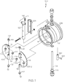
- FIG. 1 depicts an exploded view of a check valve assembly
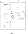
- FIG. 2 depicts a schematic cross section view of the check valve assembly of FIG. 1 ;
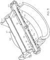
- FIG. 3 depicts a plan view of a portion of the check valve assembly of FIG. 1 .
- FIG. 1 an exploded plan view of an embodiment of a split flapper check valve assembly 100 is depicted, and includes a valve body 102, a hinge pin 104, and a pair of flappers 106 (e.g., 106-1, 106-2).
- the valve body includes an inlet port 108, an outlet port 112, and an inner surface 113 that defines a flow passage 114 between the inlet and outlet ports 108, 112.
- the hinge pin (or shaft) 104 is mounted on the valve body 102 and extends across the flow passage 114.
- the depicted hinge pin 104 is mounted on the valve body via suitable mounting hardware, and is secured via threaded bolts that thread onto like-threaded protrusions on the valve body 102.
- the depicted hinge pin 104 is adjustably coupled to the valve body 102. More specifically, the depicted hinge pin 104 includes a flange 105 that allows the axial endplay thereof to be adjusted.
- the flappers 106 are each rotationally mounted on the hinge pin 104 via a plurality of lugs 116 that are formed on each flapper 106.
- each flapper includes a relatively long lug and a relatively short lug, though this need not be the case.
- the hinge pin 104 extends into and through each of the lugs 116.
- a pair of lug bushings 118 is also associated with each of the lugs 116.
- a lug bushing 118 extends into each end of each of the lugs 116, and the hinge pin 104 extends through each lug bushing 118.
- the lug bushings 118 act as bearing surfaces as well.
- the lug bushings 118 are each configured with a load flange 119.
- the depicted valve assembly 100 additionally includes an open stop assembly 120.
- the open stop assembly 120 is coupled to the valve body 102 and extends across the flow passage 114 downstream of the flappers 106.
- the depicted open stop assembly 120 includes a main body 122 and a soft stop device 124.
- the soft stop device 124 is coupled to the main body 122, and provides a relatively flexible surface against which the flappers 106 may seat when in the open position.
- the valve body 102 additionally includes a cross bar 202.
- the cross bar 202 which is not visible in FIG. 1 , may be formed as an integral part of the valve body 102, or formed separately and coupled thereto. In either case, the cross bar 202 extends across the flow passage 114.
- the flappers 106 rest on, and transfer load to, the cross bar 202 when the flappers 106 are in the closed position (which is the position depicted in FIG. 2 ).
- FIG. 2 also depicts more clearly how the flappers 106 contact the open stop assembly 120 when in the open position.
- FIG. 3 it may be seen that when the flappers 106 are properly mounted on the hinge pin 104, the lugs 116 of each flapper 106 are interlaced.
- another bushing which is referred to herein as a grounded bushing 126, is mounted on the hinge pin 104 and is disposed between each flapper 106.
- the grounded bushing 126 is non-rotationally coupled to the hinge pin 104, and is thus "grounded" to the hinge pin 104.
- the grounded bushing 126 may be non-rotationally coupled to the hinge pin 104 using any one of numerous techniques, but in the depicted embodiment it is non-rotationally coupled via a tapered set screw 128 (or other suitable fastener). Some non-limiting alternative techniques include bolting, welding, and clamping, just to name a few. If a fastener is used, the grounded bushing 126 may be selectively releasable from the hinge pin 104.
- the one or more grounded bushings 126 provide additional surface area for controlling the axial positions of the flappers 106 along the hinge pin 104.
- the flappers 106 bear against the ends of the grounded bushing(s) 126.
- the additional bearing surface area effectively increases the overall axial bearing surface area according to the number of additional grounded lugs that are used, without increasing the diameter of the flapper lugs 116.
- grounded bushing 126 is fixedly coupled to the hinge pin 104, and because the hinge pin 104 is fixed with respect to the valve body 102, the overall effect is that there are now plural bearing surfaces (two in the depicted embodiment) that accept loads from the flappers 106, rather than just one.
- the lug bushings 118 with load flanges 119 on both ends of each flapper lug 116, the grounded bushing 126 fixedly secured between the flappers 106, and the ability to adjust the axial endplay of the hinge pin 104 ensures a close fit between the flanges 119 of the lug bushings 118 and the grounded bushing 126 will be maintained.
Landscapes
- Engineering & Computer Science (AREA)
- General Engineering & Computer Science (AREA)
- Mechanical Engineering (AREA)
- Check Valves (AREA)
Applications Claiming Priority (2)
| Application Number | Priority Date | Filing Date | Title |
|---|---|---|---|
| US201161453815P | 2011-03-17 | 2011-03-17 | |
| US13/357,147 US20120234408A1 (en) | 2011-03-17 | 2012-01-24 | Check valve with axial thrust element |
Publications (1)
| Publication Number | Publication Date |
|---|---|
| EP2500609A1 true EP2500609A1 (fr) | 2012-09-19 |
Family
ID=45894220
Family Applications (1)
| Application Number | Title | Priority Date | Filing Date |
|---|---|---|---|
| EP20120159680 Withdrawn EP2500609A1 (fr) | 2011-03-17 | 2012-03-15 | Clapet de retenue avec élément de poussée axiale |
Country Status (2)
| Country | Link |
|---|---|
| US (1) | US20120234408A1 (fr) |
| EP (1) | EP2500609A1 (fr) |
Cited By (2)
| Publication number | Priority date | Publication date | Assignee | Title |
|---|---|---|---|---|
| EP3193059A1 (fr) * | 2016-01-15 | 2017-07-19 | Hamilton Sundstrand Corporation | Clapet anti-retour |
| US11098821B1 (en) * | 2019-10-10 | 2021-08-24 | Cantex International, Inc. | Flapper valve |
Families Citing this family (7)
| Publication number | Priority date | Publication date | Assignee | Title |
|---|---|---|---|---|
| US20130333776A1 (en) * | 2012-06-15 | 2013-12-19 | Spirax Sarco, Inc. | Condensate removal pump having improved check valve |
| US9279509B2 (en) | 2013-09-09 | 2016-03-08 | Hamilton Sundstrand Corporation | Valve with precision mounted hinge pin posts |
| US9334972B2 (en) * | 2014-05-15 | 2016-05-10 | Honeywell International Inc. | Composite injection molded check valve with integrated features |
| CN106286909B (zh) * | 2016-08-29 | 2019-08-13 | 苏州纽威阀门股份有限公司 | 一种阀瓣结构及双瓣式止回阀 |
| CN112682122B (zh) | 2016-10-06 | 2022-09-09 | 博格华纳公司 | 用于可变凸轮正时系统的双瓣阀 |
| US11111827B2 (en) | 2016-10-06 | 2021-09-07 | Borgwarner, Inc. | Double flapper valve for a variable cam timing system |
| US11326483B2 (en) | 2018-12-14 | 2022-05-10 | Borgwarner Inc. | Double slope stopper usable with a variable cam timing system |
Citations (6)
| Publication number | Priority date | Publication date | Assignee | Title |
|---|---|---|---|---|
| GB870868A (en) * | 1958-10-13 | 1961-06-21 | Rotax Ltd | Non-return valves |
| US3374804A (en) * | 1965-07-07 | 1968-03-26 | Axel Larsson Maskinaffar Ab | Check valves |
| FR2583131A1 (fr) * | 1985-06-07 | 1986-12-12 | Nisshin Manufacturing Co Ltd | Soupape de retenue |
| DE3533905A1 (de) * | 1985-09-23 | 1987-04-02 | Subrat Chatterjee | Zwischenflansch-rueckschlagventil |
| US20060026965A1 (en) * | 2004-08-09 | 2006-02-09 | Christianson Eric J | Methods and apparatus for regulating airflow supply systems |
| US20090056818A1 (en) * | 2007-09-05 | 2009-03-05 | Honeywell International, Inc. | Check valves with noise reducer |
-
2012
- 2012-01-24 US US13/357,147 patent/US20120234408A1/en not_active Abandoned
- 2012-03-15 EP EP20120159680 patent/EP2500609A1/fr not_active Withdrawn
Patent Citations (6)
| Publication number | Priority date | Publication date | Assignee | Title |
|---|---|---|---|---|
| GB870868A (en) * | 1958-10-13 | 1961-06-21 | Rotax Ltd | Non-return valves |
| US3374804A (en) * | 1965-07-07 | 1968-03-26 | Axel Larsson Maskinaffar Ab | Check valves |
| FR2583131A1 (fr) * | 1985-06-07 | 1986-12-12 | Nisshin Manufacturing Co Ltd | Soupape de retenue |
| DE3533905A1 (de) * | 1985-09-23 | 1987-04-02 | Subrat Chatterjee | Zwischenflansch-rueckschlagventil |
| US20060026965A1 (en) * | 2004-08-09 | 2006-02-09 | Christianson Eric J | Methods and apparatus for regulating airflow supply systems |
| US20090056818A1 (en) * | 2007-09-05 | 2009-03-05 | Honeywell International, Inc. | Check valves with noise reducer |
Cited By (3)
| Publication number | Priority date | Publication date | Assignee | Title |
|---|---|---|---|---|
| EP3193059A1 (fr) * | 2016-01-15 | 2017-07-19 | Hamilton Sundstrand Corporation | Clapet anti-retour |
| US10088065B2 (en) | 2016-01-15 | 2018-10-02 | Hamilton Sundstrand Corporation | Check valves and flapper arrangements therefor |
| US11098821B1 (en) * | 2019-10-10 | 2021-08-24 | Cantex International, Inc. | Flapper valve |
Also Published As
| Publication number | Publication date |
|---|---|
| US20120234408A1 (en) | 2012-09-20 |
Similar Documents
| Publication | Publication Date | Title |
|---|---|---|
| EP2500609A1 (fr) | Clapet de retenue avec élément de poussée axiale | |
| EP1852641B1 (fr) | Clapet de retenue de volets d'intrados comportant un mécanisme de réduction d'usure du ressort de torsion | |
| US9581256B2 (en) | Valve flapper spring stop mechanism | |
| US9334972B2 (en) | Composite injection molded check valve with integrated features | |
| EP1930238A1 (fr) | Clapet de retenue avec pression d'ouverture réglable | |
| US8240331B2 (en) | Negative pressure relief valve assembly | |
| US20120216894A1 (en) | Valve Assembly | |
| EP3232101B1 (fr) | Butoir de soupape de non-retour à battant | |
| EP3043047B1 (fr) | Dispositif de réglage de débit de gaz | |
| US8714190B2 (en) | Metal plate for dual plate check valve | |
| US11231049B2 (en) | Blower and a blower diffuser | |
| US8276880B2 (en) | Butterfly valve plate sealing assembly | |
| US7954509B2 (en) | Check valves with hinge shafts retained by welding | |
| US20090032120A1 (en) | Check valves with hinge shafts retained by locking pins | |
| US20090032118A1 (en) | Check valves with hinge shafts retained by bushings | |
| US20140251461A1 (en) | Check valve having petals with lift generating elements | |
| US9157537B2 (en) | Aircraft fluid check valve assembly with indexing | |
| US9625054B2 (en) | Shut-off flap | |
| US20100236650A1 (en) | Butterfly valve combined with check valve | |
| US7334773B2 (en) | Outflow valve having a cable operated closure mechanism | |
| US20220163119A1 (en) | Butterfly valve device | |
| EP3205872A1 (fr) | Dispositif de réduction du bruit à l'admission | |
| US10648581B2 (en) | Check valves | |
| EP3495703B1 (fr) | Clapets anti-retour | |
| US20090159827A1 (en) | Rotary gate valve |
Legal Events
| Date | Code | Title | Description |
|---|---|---|---|
| PUAI | Public reference made under article 153(3) epc to a published international application that has entered the european phase |
Free format text: ORIGINAL CODE: 0009012 |
|
| 17P | Request for examination filed |
Effective date: 20120315 |
|
| AK | Designated contracting states |
Kind code of ref document: A1 Designated state(s): AL AT BE BG CH CY CZ DE DK EE ES FI FR GB GR HR HU IE IS IT LI LT LU LV MC MK MT NL NO PL PT RO RS SE SI SK SM TR |
|
| AX | Request for extension of the european patent |
Extension state: BA ME |
|
| STAA | Information on the status of an ep patent application or granted ep patent |
Free format text: STATUS: THE APPLICATION IS DEEMED TO BE WITHDRAWN |
|
| 18D | Application deemed to be withdrawn |
Effective date: 20130122 |