EP2500638B1 - Scheinwerfervorrichtung - Google Patents
Scheinwerfervorrichtung Download PDFInfo
- Publication number
- EP2500638B1 EP2500638B1 EP12151068.9A EP12151068A EP2500638B1 EP 2500638 B1 EP2500638 B1 EP 2500638B1 EP 12151068 A EP12151068 A EP 12151068A EP 2500638 B1 EP2500638 B1 EP 2500638B1
- Authority
- EP
- European Patent Office
- Prior art keywords
- base member
- headlamp device
- intermediate member
- light source
- internal space
- Prior art date
- Legal status (The legal status is an assumption and is not a legal conclusion. Google has not performed a legal analysis and makes no representation as to the accuracy of the status listed.)
- Not-in-force
Links
- 238000005192 partition Methods 0.000 claims description 14
- 230000002093 peripheral effect Effects 0.000 claims description 14
- 230000000644 propagated effect Effects 0.000 claims description 6
- 229920005989 resin Polymers 0.000 description 6
- 239000011347 resin Substances 0.000 description 6
- 239000000463 material Substances 0.000 description 5
- 229920003002 synthetic resin Polymers 0.000 description 5
- 239000000057 synthetic resin Substances 0.000 description 5
- 230000002787 reinforcement Effects 0.000 description 4
- 238000001816 cooling Methods 0.000 description 3
- 238000005286 illumination Methods 0.000 description 3
- 239000004412 Bulk moulding compound Substances 0.000 description 2
- 229920002430 Fibre-reinforced plastic Polymers 0.000 description 2
- 239000004743 Polypropylene Substances 0.000 description 2
- 230000005540 biological transmission Effects 0.000 description 2
- 239000011151 fibre-reinforced plastic Substances 0.000 description 2
- 239000002828 fuel tank Substances 0.000 description 2
- 229920001155 polypropylene Polymers 0.000 description 2
- XLYOFNOQVPJJNP-UHFFFAOYSA-N water Substances O XLYOFNOQVPJJNP-UHFFFAOYSA-N 0.000 description 2
- 239000004676 acrylonitrile butadiene styrene Substances 0.000 description 1
- XAGFODPZIPBFFR-UHFFFAOYSA-N aluminium Chemical compound [Al] XAGFODPZIPBFFR-UHFFFAOYSA-N 0.000 description 1
- 229910052782 aluminium Inorganic materials 0.000 description 1
- 238000005266 casting Methods 0.000 description 1
- 238000002485 combustion reaction Methods 0.000 description 1
- 230000006835 compression Effects 0.000 description 1
- 238000007906 compression Methods 0.000 description 1
- 230000008021 deposition Effects 0.000 description 1
- 239000000428 dust Substances 0.000 description 1
- 230000000694 effects Effects 0.000 description 1
- 230000002708 enhancing effect Effects 0.000 description 1
- 229910052736 halogen Inorganic materials 0.000 description 1
- 150000002367 halogens Chemical class 0.000 description 1
- 239000002861 polymer material Substances 0.000 description 1
- -1 polypropylene Polymers 0.000 description 1
- 230000001737 promoting effect Effects 0.000 description 1
- 230000005855 radiation Effects 0.000 description 1
- 230000011664 signaling Effects 0.000 description 1
- 239000000725 suspension Substances 0.000 description 1
- 238000011144 upstream manufacturing Methods 0.000 description 1
Images



Classifications
-
- B—PERFORMING OPERATIONS; TRANSPORTING
- B60—VEHICLES IN GENERAL
- B60Q—ARRANGEMENT OF SIGNALLING OR LIGHTING DEVICES, THE MOUNTING OR SUPPORTING THEREOF OR CIRCUITS THEREFOR, FOR VEHICLES IN GENERAL
- B60Q1/00—Arrangement of optical signalling or lighting devices, the mounting or supporting thereof or circuits therefor
- B60Q1/26—Arrangement of optical signalling or lighting devices, the mounting or supporting thereof or circuits therefor the devices being primarily intended to indicate the vehicle, or parts thereof, or to give signals, to other traffic
- B60Q1/2607—Arrangement of optical signalling or lighting devices, the mounting or supporting thereof or circuits therefor the devices being primarily intended to indicate the vehicle, or parts thereof, or to give signals, to other traffic comprising at least two indicating lamps
-
- B—PERFORMING OPERATIONS; TRANSPORTING
- B60—VEHICLES IN GENERAL
- B60Q—ARRANGEMENT OF SIGNALLING OR LIGHTING DEVICES, THE MOUNTING OR SUPPORTING THEREOF OR CIRCUITS THEREFOR, FOR VEHICLES IN GENERAL
- B60Q1/00—Arrangement of optical signalling or lighting devices, the mounting or supporting thereof or circuits therefor
- B60Q1/0029—Spatial arrangement
- B60Q1/0041—Spatial arrangement of several lamps in relation to each other
- B60Q1/0047—Signalling unit mounted on a headlamp unit
-
- B—PERFORMING OPERATIONS; TRANSPORTING
- B62—LAND VEHICLES FOR TRAVELLING OTHERWISE THAN ON RAILS
- B62J—CYCLE SADDLES OR SEATS; AUXILIARY DEVICES OR ACCESSORIES SPECIALLY ADAPTED TO CYCLES AND NOT OTHERWISE PROVIDED FOR, e.g. ARTICLE CARRIERS OR CYCLE PROTECTORS
- B62J6/00—Arrangement of optical signalling or lighting devices on cycles; Mounting or supporting thereof; Circuits therefor
- B62J6/02—Headlights
- B62J6/022—Headlights specially adapted for motorcycles or the like
- B62J6/026—Headlights specially adapted for motorcycles or the like characterised by the structure, e.g. casings
-
- F—MECHANICAL ENGINEERING; LIGHTING; HEATING; WEAPONS; BLASTING
- F21—LIGHTING
- F21S—NON-PORTABLE LIGHTING DEVICES; SYSTEMS THEREOF; VEHICLE LIGHTING DEVICES SPECIALLY ADAPTED FOR VEHICLE EXTERIORS
- F21S41/00—Illuminating devices specially adapted for vehicle exteriors, e.g. headlamps
- F21S41/50—Illuminating devices specially adapted for vehicle exteriors, e.g. headlamps characterised by aesthetic components not otherwise provided for, e.g. decorative trim, partition walls or covers
-
- F—MECHANICAL ENGINEERING; LIGHTING; HEATING; WEAPONS; BLASTING
- F21—LIGHTING
- F21S—NON-PORTABLE LIGHTING DEVICES; SYSTEMS THEREOF; VEHICLE LIGHTING DEVICES SPECIALLY ADAPTED FOR VEHICLE EXTERIORS
- F21S45/00—Arrangements within vehicle lighting devices specially adapted for vehicle exteriors, for purposes other than emission or distribution of light
- F21S45/30—Ventilation or drainage of lighting devices
- F21S45/33—Ventilation or drainage of lighting devices specially adapted for headlamps
Definitions
- the present invention relates to a headlamp device including a headlight light source and a position-light light source.
- Patent Document 1 discloses a headlamp structure (device) in which a headlight bulb (headlight light source) and position light bulbs (position-light light sources) are provided in one unit.
- the position light bulbs are disposed on vehicle-width-directionally outer upper sides of the headlight bulb, and reflectors (a vertical wall portion and an upper wall surface) are provided on the front and rear sides of the position light bulb.
- the reflectors reflect the light emitted from the position light bulb, whereby the light in a predetermined quantity is radiated as position light to the outside of the headlamp device.
- Patent Document 2 discloses an automotive headlamp that includes a lamp body, a reflector, a light source and an inner lens that is provided in front of an outer lens, wherein the inner lens is formed with an air path.
- Patent Document 3 discloses a light unit that has an aperture frame with reflector chambers in two stacked planes with the chamber for the flasher light beneath the chambers for dipped and main beams and/or for signaling lights, a cover panel and an arrangement for ventilating the inner volume.
- Patent Document 4 discloses a vehicular headlamp including two lamp units and an extension for covering gaps among a lamp body and the lamp units.
- Patent Document 5 discloses a headlamp for automobile comprising an inner cover that is extended between projection lamps and a lamp body to cover a lamp chamber. Furthermore, the headlamp is provided with an air inflow hole and air outflow hole for forming natural convection in the lamp chamber at the right and left positions on the back face side of the lamp chamber.
- a headlamp device during when a headlight and position lights are turned on, heat is generated attendantly on the emission of light from the headlight bulb and the position light bulbs. Especially, from the headlight radiating a large quantity of light, a large quantity of heat is transmitted to air present in the internal space of the headlamp device, and the heat stagnates in the internal space. As a result, water contained in the air in the internal space is warmed up to cause fogging (deposition of water droplets) on a lens. The fogging on the lens lowers the quantity of light emitted when the headlamp device is on. In particular, where an intermediate cover member (intermediate member) for hiding a base member in the surroundings of the reflectors is provided, the space inside the headlight is reduced and, therefore, the influence of the fogging becomes further conspicuous.
- the heat of the headlight bulb and the heat of the position light bulbs are locally concentrated in a certain part, which may cause a deformation at the part under the influence of the heat.
- the present invention has been made in consideration of the above-mentioned circumstances. Accordingly, it is an object of the present invention to provide a headlamp device in which fogging on lens in the headlamp device can be restrained and deformation of members constituting the headlamp device can be prevented by promoting release of heat from within the internal space of the headlamp device, while using a simple configuration.
- a headlamp device (10) including: a base member (100) on which to dispose a headlight light source (106) and a position-light light source (108); a lens (102) mounted to a front portion of the base member (100); a reflector (122) which is disposed in an internal space (114) defined by the base member (100) and the lens (102) and which reflects light emitted by the headlight light source (106); and an intermediate member (130) which covers the base member (100) at least in the surroundings of the reflector (122) in front view, is characterized in that the intermediate member (130) is provided with a cutout (144) which permits a gas present on the lens (102) side relative to the intermediate member (130) to flow therethrough to the base member (100) side relative to the intermediate member (130).
- the headlamp device is characterized in that an upper edge part (100a) of the base member (100) is formed to be hollowed in a central portion thereof, and both left and right edges continuous with the central portion are inclined obliquely upward.
- a lower edge part (100b) is smaller in width than the upper edge part (100a), and is slowly inclined obliquely upward along vehicle-width-directionally outward directions.
- a pair of left and right side edge parts (100c, 100c) are inclined obliquely downward along vehicle-width-directionally outward directions from top portions (100d, 100d) continuous with the upper edge part (100a), are bent at side end portions (100e, 100e) and are inclined obliquely downward toward the center, to be continuous with the lower edge part (100b).
- the headlamp device (10) according to claim 1 is characterized in that the intermediate member (130) is disposed in the internal space (114) so as to form a predetermined gap (164) between itself and the reflector (122).
- the headlamp device (10) is characterized in that the base member (100) has a gas supply hole (148, 150) for taking a gas into the internal space (114) and a gas exhaust hole (152, 154, 156) for exhausting the gas from inside the internal space (114), and the intermediate member (130) ensures that the gas taken in through the gas supply hole (148, 150) and moved to the lens (102) side can be guided through the cutout (144) to the gas exhaust hole (152, 154, 156).
- two cutouts (144) are provided on the upper side of said headlight light source (106) and are provided on the outer side of the intermediate member (130) in the vehicle width direction, so as to be close to the pair of left and right side edge parts (100c, 100c).
- the headlamp device (10) is further characterized in that the gas supply hole (150) is provided on the lower side of the base member (100), and the gas exhaust hole (152, 154, 156) is provided on the upper side of the base member (100).
- the headlamp device (10) according to any one of claims 1 to 2 is characterized in that the intermediate member (130) has a partition wall (146) on an imaginary straight line interconnecting the headlight light source (106) and the position-light light source (108), and the partition wall (146) shieldingly prevents radiant heat generated from the headlight light source (106) or the position-light light source (108) from being propagated directly toward other light source.
- the intermediate member (130) has a partition wall (146) on an imaginary straight line interconnecting the headlight light source (106) and the position-light light source (108), and the partition wall (146) shieldingly prevents radiant heat generated from the headlight light source (106) or the position-light light source (108) from being propagated directly toward other light source.
- the cutout ensures that the gas present on the lens side relative to the intermediate member can flow therethrough to the base member side relative to the intermediate member, whereby convection of the gas can be generated in the internal space of the headlamp device, and release of heat from within the internal space is accelerated.
- the heat generated from the headlight light source and the position-light light source can be prevented from stagnating on the lens side, and fogging on the lens can be restrained from occurring.
- the release of heat from within the internal space is promoted, such troubles as deformation of the members constituting the headlamp device can also be prevented from occurring.
- the intermediate member is so disposed as to form a predetermined gap between itself and the reflector. This ensures that the gas present in the internal space can flow into and through the gap between the internal member and the reflector, and the gas can flow more smoothly. Consequently, the release of heat from within the internal space can be more accelerated.
- the intermediate member ensures that the gas taken in through the gas supply hole and moved to the lens side can be guided through the cutout to the gas exhaust hole. Therefore, the heat generated from the headlight light source and the position-light light source can be easily guided to the gas exhaust hole, so that the release of heat from within the internal space can be further promoted.
- a cold gas can be taken in through the gas supply hole on the lower side of the base member to thereby cool the internal space. Further, the gas warmed up in the internal space can be exhausted through the gas exhaust hole on the upper side by convection. In other words, the convection of heat within the internal space can be utilized efficiently, and the release of heat from within the internal space can be accelerated further.
- the radiant heat generated from the headlight light source or the position-light light source is shieldingly prevented from being propagated directly toward other light source, whereby mutual thermal influences between the headlight light source and the position-light light source can be greatly reduced. Consequently, such troubles as deformation of the members constituting the headlamp device can also be prevented from occurring.
- FIG. 1 is a schematic side view of a saddle type motorcycle (hereinafter referred also to simply as motorcycle) 12 having a headlamp device 10 according to an embodiment of the present invention.
- the present invention will be described in detail by showing the saddle type motorcycle as an example, but the invention is not to be restricted to the saddle type motorcycle, and, naturally, the invention is also applicable to other types of motorcycles or motorbikes, etc.
- the forward and rearward directions FRONT, REAR
- UP, DOWN upward and downward directions
- UP, DOWN upward and downward directions
- LEFT, RIGHT leftward and rightward directions
- the motorcycle 12 includes a front wheel 14 as a steering wheel, a handlebar 16 for steering the front wheel 14, a body frame 18 constituting a vehicle body, an engine 20 as a drive source, a rear wheel 22 as a drive wheel, and a seat 24 on which to seat the rider(s).
- the front wheel 14 is steerably borne on the lower end side of a front fork 26 having a pair of parts extending roughly vertically.
- a front fender 28 covering the upper side of the front wheel 14 is mounted to the front fork 26.
- the handlebar 16 is connected to the upper end side of the front fork 26, and a roughly middle portion of the front fork 26 is turnably borne on a head pipe 30 possessed by the body frame 18.
- the handlebar 16 extends in the vehicle width direction in left-right symmetry, with its joint part to the front fork 26 as a center of symmetry. Grips 16a to be gripped by the driver are respectively mounted to both end portions of the handlebar 16.
- the body frame 18 is composed, for example, of a tube frame of aluminum casting which is high in rigidity.
- the body frame 18 includes: a main frame 32 extending rearward from an upper portion of the head pipe 30 and being slowly inclined obliquely downward; a down frame 34 extending rearward from a lower portion of the head pipe 30 and being rapidly inclined obliquely downward; a pair of left and right pivot plates 36 connected to a rear end portion of the main frame 32 and extending downward from a roughly middle portion of the vehicle body; a seat frame 38 obliquely extending rearwardly upward from a roughly middle portion of the main frame 32; and a reinforcement frame 40 connected to the upper ends of the pivot plates 36 and extending obliquely upward toward a rear end portion of the seat frame 38.
- a plurality of front-side reinforcement stays 42 are connected between the main frame 32 and the down frame 34.
- a plurality of rear-side reinforcement stays 44 are connected between the seat frame 38 and the reinforcement frame 40.
- the engine 20 includes a cylinder block 46 and a crankcase 48.
- the engine 20 may be, for example, of an in-line 4-cylinder type.
- the engine 20 has a configuration in which a front end portion of the crankcase 48 is supported by the down frame 34, and a rear end portion of the crankcase 48 is supported by upper end portions of the pivot plates 36, whereby the engine 20 is fixed in such an attitude that the cylinder axis in the cylinder block 46 is inclined forwardly upward.
- a spark plug for combustion and a piston for compression are contained in the cylinder block 46.
- a crankshaft connected to the piston through a connecting rod and an engine output shaft are rotatably supported, and a clutch mechanism and a transmission and the like constituting a power transmission mechanism are contained between the shafts.
- a rotational driving force of the engine 20 is transmitted from the engine output shaft in the crankcase 48 to an endless drive chain 50, and is transmitted through the drive chain 50 to the rear wheel 22.
- a radiator (not shown) for radiating heat from the engine 20 is disposed forwardly of the cylinder block 46.
- a fuel tank 52 and an intake system 54 are mounted on the upper side of the engine 20.
- the intake system 54 has an intake port 56 connected to an upper portion of the cylinder block 46, and an air cleaner 58 provided at an upstream end of the intake port 56.
- the air cleaner 58 is disposed so as to be covered with the fuel tank 52, and adsorbs dust and the like present in air taken in through the double-structured cowl which will be described later.
- an exhaust system 60 is connected to a front portion of the cylinder block 46.
- the exhaust system 60 includes a plurality of exhaust pipes 62 extending downward from the cylinder block 46 in individual correspondence with the cylinders, and an exhaust muffler 64 disposed on the right side of the rear wheel 22 so as to be continuous with each of the exhaust pipes 62.
- a swing arm 66 is borne at its front end portion so that it can be swung upward and downward. Further, a suspension 68 for absorbing vibrations is attached to a front portion side of the swing arm 66, and the rear wheel 22 is rotatably supported on rear end portions of the swing arm 66. Furthermore, pillion steps 70 extending rearward are fixed to the pivot plates 36, and step holders 70a on which to put the driver's and passenger's feet are attached thereto.
- the seat 24 on which the riders (the driver and the passenger) are to be seated is disposed on the seat frame 38.
- the seat 24 there is adopted a so-called tandem type seat having a front seat 24a on which the driver is to be seated and a rear seat 24b on which the passenger is to be seated rewarwardly of the front seat 24a.
- a rear fender 72 roughly arcuate in shape in side view is mounted to a rear portion of the seat frame 38.
- Rear-side winker lamps 74 and a tail lamp 76 as lighting parts on the vehicle rear portion side are attached to the rear fender 72, and a license plate 78 is mounted under the tail lamp 76.
- a body cover 80 constituting design surfaces (external appearance) of the vehicle body along the back-and-forth direction of the vehicle body is mounted on the motorcycle 12.
- the body cover 80 is formed, for example, from a polymer material such as acrylonitrile-butadiene-styrene (ABS), fiber-reinforced plastic (FRP) or polypropylene (PP).
- the body cover 80 includes: a front cowl 82 constituting a design of a body front portion; a pair of left and right inner cowls 84 provided continuously with and on the rear side of both side surfaces of the front cowl 82 and extending rearward from both lateral sides; a pair of left and right outer cowls 86 partly covering the inner cowls 84 on the outer sides of the inner cowls 84; a pair of left and right middle cowls 88 provided continuously with and on the rear side of the inner cowls 84 and extending to the lower side of the front seat 24a; and a rear cowl 90 provided continuously with and on the rear side of the middle cowls 88 and extending rearward along the seat frame 38.
- the front cowl 82 is formed in such a shape as to cover a roughly middle portion of the front fork 26 and the head pipe 30 on the front side of them.
- the headlamp device 10 is disposed which illuminates the front side of the vehicle during traveling.
- a front screen 92 formed in such a shape as to relieve resistance of an airflow induced by traveling of the vehicle is attached to the front cowl 82, and a pair of left and right rearview mirrors 94 are mounted on both sides in the vehicle width direction of the front screen 92.
- a meter unit 96 is disposed in which meters such as a speedometer and a tachometer are contained.
- the inner cowl 84 and the outer cowl 86 are mounted to both side surfaces of the front of the motorcycle 12 as a double-structured cowl. Since the double-structured cowl composed of the inner cowl 84 and the outer cowl 86 is thus provided, air can be taken in via a gap formed between the two cowls, and the air can be easily guided to the air cleaner 58.
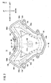
- FIG. 2 is a front view of the headlamp device 10 of FIG. 1 ;
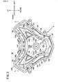
- FIG. 3 is a front view of the headlamp device 10 of FIG. 2 , with a lens 102 removed;
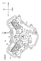
- FIG. 4 is a back elevation showing the rear side of the headlamp device 10 of FIG. 2 ;
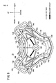
- FIG. 5 is a front view of a base member 100 of the headlamp device 10 of FIG. 2 ;
- FIG. 6 is a front view of an intermediate member 130 of FIG. 3 ;
- FIG. 7 is a sectional view taken along line VII-VII.
- the headlamp device 10 includes, in one unit, a headlight bulb (headlight light source) 106 for illuminating as a headlamp (headlight) and two position light bulbs (position-light light sources) 108, 108 for lighting as position lights.
- the headlamp device 10 has a casing which includes the base member 100 supporting the headlight bulb 106 and the position light bulbs 108, 108, and the lens 102 mounted to a front portion of the base member 100.
- the base member 100 is formed in a roughly heart-like shape in front view. More specifically, an upper edge part 100a of the base member 100 is formed to be hollowed in a central portion thereof, and both left and right edges continuous with the central portion are inclined obliquely upward. Besides, a lower edge part 100b is smaller in width than the upper edge part 100a, and is slowly inclined obliquely upward along vehicle-width-directionally outward directions.
- a pair of left and right side edge parts 100c, 100c are inclined obliquely downward along vehicle-width-directionally outward directions from top portions 100d, 100d continuous with the upper edge part 100a, are bent at predetermined positions (side end portions 100e, 100e) and are inclined obliquely downward toward the center, to be continuous with the lower edge part 100b.
- the base member 100 is formed in a roughly concave box-like shape in side sectional view.
- a bottom portion of the concave shape of the base member 100 is formed in an arcuate shape as a rear side wall part 110.
- the rear side wall part 110 is provided at its peripheral edge with the upper edge part 100a, the lower edge part 100b and the side edge parts 100c, 100c (hereinafter, these parts will collectively be referred to also as peripheral edge part 101).
- the peripheral edge part 101 of the base member 100 is provided at the front thereof with a mounting groove 112 into which a rear-side opening end part 102a of the lens 102 is to be inserted.
- the base member 100 is molded from a synthetic resin material endurable to a temperature rise attendant on light emission from the headlight bulb 106 and the position light bulbs 108.
- a synthetic resin material for example, a BMC (Bulk Molding Compound) resin or the like is preferably adopted.
- the lens 102 is molded from a highly transparent synthetic resin material, in such an outer shape as to be roughly coincident with the shape of the peripheral edge part 101 of the base member 100 in front view, as shown in FIG. 2 .
- the lens 102 is mounted at its rear-side opening end part 102a to the mounting groove 112 of the base member 100, without any gap therebetween. This ensures that rainwater or the like would not enter into an internal space 114 (see FIG. 7 ) formed by the mounting of the base member 100 and the lens 102 to each other.
- the lens 102 has a configuration in which, in side sectional view as shown in FIG. 7 , a side peripheral surface 102b projects forward from the rear-side opening end part 102a, and a front surface part 102c is formed in a roughly arcuate shape slowly bulging increasingly from the upper side toward the lower side.
- the shape of the front surface part 102c of the lens 102 is so set as to be continuous with the design surface of the front cowl 82 (see FIG. 1 ).
- the lens 102 of the headlamp device 10 and the front cowl 82, at the front of the vehicle body constitute a streamline-shaped design which is slowly inclined in vehicle-width-directionally outward and upward from a tip central portion toward the rear side.
- the headlight bulb 106 is mounted in a center position of the base member 100 formed in the roughly heart-like shape.
- the headlight bulb 106 for example, a halogen lamp or an HID lamp or the like can be applied.
- the headlamp device 10 may have an LED lamp or the like, instead of the headlight bulb 106, as the headlight light source.
- the headlight bulb 106 has a base portion 106a to which anode and cathode wirings 116 are connected, and a light emitting portion 106c projecting from the base portion 106a toward the lens 102.
- the base portion 106a is supported by a support member 118 attached to the rear side wall part 110 of the base member 100.
- the support member 118 is mounted in a mounting hole 120 (see FIG. 5 ) formed in a roughly central portion of the rear side wall part 110.
- a central portion projects toward the lens 102 and is provided at its tip portion with a fixing hole 118a in which the base portion 106a of the headlight bulb 106 is fixed and supported.
- the headlight bulb 106 as a whole is supported roughly horizontally, with its base portion 106a fitted in the fixing hole 118a. Besides, the light emitting portion 106b of the headlight bulb 106 is provided therein with a filament, and emits light in a predetermined quantity when supplied with electric power through the wiring 116, based on the driver's light turning-on operation.
- a reflector 122 is attached by which the light emitted from the headlight bulb 106 is reflected.
- the reflector 122 is formed in a curved surface (for example, quadric surface) such that the light emitted from the headlight bulb 106 to the side periphery is reflected thereby toward the forward side.
- the two position light bulbs 108, 108 are respectively mounted at vehicle-width-directionally outer upper positions on the base member 100. These position light bulbs 108, 108 are turned on for enhancing the assuredness with which the motorcycle 12 can be visually recognized by the oncoming vehicles. Therefore, light bulbs lower in light emission capacity than the headlight bulb 106 are applied as the position light bulbs 108, 108.
- the base member 100 is provided with two mounting holes 124, 124 at vehicle-width-directionally outer upper positions thereof, and the position light bulbs 108, 108 are mounted in the mounting holes 124, 124 respectively.
- stepped parts 126, 126 are provided by which the light emitted from the position light bulbs 108, 108 is reflected into a predetermined direction.
- the stepped parts 126, 126 function as reflectors for the position light bulbs 108.
- wall parts 128, 128 are erectly provided in the peripheries of the mounting holes 124, 124 of the base member 100.
- the wall parts 128, 128 are formed in a roughly V shape in front view, and extend toward the center (toward the mounting hole 120) from bent portions (top portions) 128a, 128a located at vehicle-width-directionally outer upper positions, while surrounding the mounting holes 124, 124 by two edge portions thereof.
- Each of the wall parts 128, 128 is open only toward the mounting hole 120, and a part of the reflector 122 extends toward the open part.
- the wall parts 128, 128 cooperate with the outer surface of the reflector 122 in surrounding the position light bulbs 108, 108, to thereby form spaces shielded from the headlight bulb 106.
- the position light bulbs 108, 108 are disposed in comparatively narrow spaces shielded by the reflector 122 and the wall parts 128, 128, whereby the quantities of light and illumination directions in emission of light from the position light bulbs 108, 108 are set appropriately.
- an intermediate member 130 is disposed on the front side of the position light bulbs 108, 108. Front surfaces of the position light bulbs 108, 108 are covered by cover members 138, 138 which are mounted to the intermediate member 130.
- the intermediate member 130 is molded from an opaque synthetic resin material pigmented in a predetermined color, and is disposed between the lens 102 and the reflector 122 in the internal space 114 of the headlamp device 10. Specifically, the intermediate member 130 is disposed at the rear of the transparent lens 102, and is visually recognized through the lens 102 when the headlamp device 10 is viewed from the front side. Therefore, the intermediate member 130 has a shape so designed as to engage with the lens 102 and thereby to enhance external appearance (aesthetic appearance) of the headlamp device 10.
- the intermediate member 130 is a little smaller than the peripheral edge part 101 of the base member 100 and the side peripheral surface 102b of the lens 102 and has an outer shape roughly coincident with the peripheral edge part 101, in front view. Accordingly, in the state where the intermediate member 130 is disposed in the internal space 114, the intermediate member 130 serves as a design surface hiding the rear side wall part 110 of the base member 100, as shown in FIG. 2 .
- the intermediate member 130 is provided in a front central portion thereof with a headlight aperture 132 for guiding the illumination of headlamp by the headlight bulb 106.
- the headlight aperture 132 is defined by an upper end edge part 132a and lower-side side end edge parts 132b, 132b which are slowly curved to be protuberant inward, and a lower end edge part 132c and upper-side side end edge parts 132d, 132d which are slowly curved to be protuberant outward.
- the headlight bulb 106 is disposed in a central position of the headlight aperture 132.
- the distance from the upper end edge part 132a to the headlight bulb 106 and the distances from the lower-side side end edge parts 132b, 132b to the headlight bulb 106 appear to be equal, while the distance from the lower end edge part 132c to the headlight bulb 106 and the distances from the upper-side side end edge parts 132d, 132d to the headlight bulb 106 appear to be equal.
- a pair of left and right shield parts 134, 134 are formed which cover the position light bulbs 108, 108.
- the shield parts 134, 134 each include a roughly triangular resin part 136, 136 inclined toward a vehicle-width-directionally outer upper side from the upper-side side end edge part 132d, 132d of the headlight aperture 132, and a cover member 138, 138 so fitted as to surround the two edges of the resin part 136, 136 and extending further toward an obliquely upper side.
- the resin parts 136, 136 are formed integrally with the intermediate member 130, whereas the cover members 138, 138 are formed from a semi-transparent synthetic resin material as separate members.
- the semi-transparent cover members 138, 138 which are disposed on the rear side of the opaque resin parts 136, 136 and surround the resin parts 136, 136.
- the shield parts 134, 134 function to permit a predetermined quantity of light from the position light bulbs 108, 108 to be transmitted therethrough to the exterior of the headlamp device 10, while covering the position light bulbs 108, 108.
- the intermediate member 130 is screwed to the rear-side opening end part 102a of the lens 102, and is held by the lens 102 (see FIG. 7 ). Therefore, the intermediate member 130 is provided with an upper edge mounting part 140 and a pair of left and right side edge mounting parts 142, 142 which extend outward from the peripheries of the headlight aperture 132 and the shield parts 134.
- the upper edge mounting part 140 and the side edge mounting parts 142, 142 are each provided with a plurality of screw holes 143.
- the intermediate member 130 is provided with a pair of left and right cutouts 144, 144 on the upper side of the side edge mounting parts 142, 142.
- the cutouts 144, 144 have predetermined depth and width in relation to the peripheral edges of the side edge mounting parts 142, 142. In the condition where the intermediate member 130 is disposed in the internal space 114, the cutouts 144, 144 ensure that air in convection to the lens 102 side relative to the intermediate member 130 can flow to the base member 100 side.
- FIG. 8 is a partial perspective view of the headlamp device 10 of FIG. 3 , as viewed from the direction of arrow A.
- the intermediate member 130 is formed with partition walls 146, 146 on the rear side of the upper-side side end edge parts 132d, 132d of the headlight aperture 132.
- the partition walls 146, 146 are proximate to a peripheral end part 122a of the reflector 122 disposed on the rear side of the intermediate member 130.
- the partition walls 146, 146 are formed on imaginary straight lines L each of which interconnects the headlight bulb 106 and the position light bulb 108 (see FIG. 3 ).
- partition wall 146 is interposed between the headlight bulb 106 and each of the position light bulbs 108, 108.
- the partition walls 146, 146 can prevent the radiant heat generated from the headlight bulb 106 (or the position light bulbs 108, 108) at the time of light emission from being propagated directly toward the cover members 138, 138.
- the headlamp device 10 is provided with a distribution mechanism for distributing air into the internal space 114 defined by the base member 100 and the lens 102, for releasing the heat generated by emission of light from the headlight bulb 106 and the position light bulbs 108, 108. More specifically, as shown in FIG. 5 , the rear side wall part 110 of the base member 100 is provided with a plurality of gas supply holes (first and second gas supply holes 148, 150) for taking air into the internal space 114, and a plurality of gas exhaust holes (first to third gas exhaust holes 152, 154, 156) for exhausting air from the internal space 114.
- first and second gas supply holes 148, 150 for taking air into the internal space 114
- gas exhaust holes first to third gas exhaust holes 152, 154, 156
- the first gas supply hole 148 is provided on a lateral side of the mounting hole 120, whereas the second gas supply hole 150 is provided on the lower side of the base member 100.
- the first and second gas supply holes 148, 150 are connected respectively with gas supply pipes 158 (see FIGS. 4 and 7 ) provided on the back side of the base member 100, and the gas supply pipes 158 are each connected to a breather (not shown).
- the outside air for example, cooling air such as an airflow induced by the traveling of the vehicle
- the outside air is sent from the breather, and it can be taken into the internal space 114 of the headlamp device 10 through the first and second gas supply holes 148, 150.
- the first gas exhaust hole 152 is provided on the upper side of the mounting hole 120, while the second and third gas exhaust holes 154, 156 are provided in the vicinity of the mounting holes 124 of the position light bulbs 108 at positions partitioned by the wall parts 128, 128.
- the first to third gas exhaust holes 152, 154, 156 are connected respectively with gas exhaust pipes 160 (see FIGS. 4 and 7 ) provided on the back side of the base member 100 so that air in convection in the internal space 114 of the headlamp device 10 is exhausted to the outside of the headlamp device 10.
- the headlamp device 10 in the present embodiment has a configuration in which in the condition where the members are assembled together, the lens 102, the intermediate member 130, the reflector 122 (and the headlight bulb 106) and the base member 100 are disposed in this order from the front side toward the rear side.
- the peripheral end part 122a of the reflector 122 is roughly coincident with the upper end edge part 132a, the lower-side side end edge parts 132b, 132b, the lower end edge part 132c and the upper-side side end edge parts 132d, 132d which form the headlight aperture 132.
- the intermediate member 130 in the present embodiment hides the peripheral end part 122a of the reflector 122, whereby the external appearance of the headlamp device 10 is enhanced.
- the upper edge mounting part 140 and the side edge mounting parts 142 of the intermediate member 130 are screwed to the rear surface side of the lens 102 through the screw holes 143.
- the intermediate member 130 is held in the internal space 114 by the lens 102. This ensures that a first gap 162 having a predetermined spacing is formed between the rear surface of the lens 102 and the front surface of the intermediate member 130.
- a second gap 164 is formed between the intermediate member 130 and the reflector 122.
- the intermediate member 130 is spaced from the reflector 122 by a predetermined spacing.
- the partition walls 146, 146 formed at the upper-side side end edge parts 132d, 132d are disposed at positions proximate to the peripheral end part 122a of the reflector 122.
- the motorcycle 12 having the headlamp device 10 according to the present embodiment is basically configured as above-described. Now, operation and effect of the headlamp device 10 will be described below.
- the motorcycle 12 causes the headlight bulb 106 to emit light when a headlight turning-on operation is conducted by the driver.
- the light emitted forward from the headlight bulb 106 is transmitted through the lens 102, to be radiated directly to the forward side of the headlamp device 10.
- the light emitted from the headlight bulb 106 to the surroundings is reflected by the reflector 122, to be transmitted through the lens 102 and radiated toward the forward side of the headlamp device 10.
- the headlamp device 10 can perform an illuminating operation to emit a predetermined quantity of light.
- the motorcycle 12 causes the two position light bulbs 108, 108 possessed by the headlamp device 10 to emit light when a position light turning-on operation is conducted.
- the light emitted from the position light bulbs 108, 108 is controlled to a predetermined light quantity and a predetermined illumination direction by the shielded spaces (the reflector 122, the wall parts 128, 128) relevant to the position light bulbs 108, 108 and the shield parts 134, 134 of the intermediate member 130, to be radiated through the cover members 138, 138 covering the front surface.
- the headlamp device 10 emission of light from the headlight bulb 106 and the position light bulbs 108, 108 is attended by generation of heat from each of the light bulbs. As a result, the heat is transmitted to air present in the internal space 114, whereby the temperature of the headlamp device 10 as a whole is raised.
- the headlamp device 10 according to the present embodiment is so configured that the heat generated from the headlight bulb 106 and the position light bulbs 108, 108 is discharged by utilizing convection inside the internal space 114.
- the outside air (for example, the airflow induced by the traveling of the vehicle) is supplied (let flow) into the headlamp device 10 through the first and second gas supply holes 148, 150 provided in the base member 100, and heated air (hereinafter referred to also as hot air) inside the headlamp device 10 is exhausted (let flow out) through the first to third gas exhaust holes.
- heated air hereinafter referred to also as hot air
- the outside air supplied through the first gas supply hole 148 is used mainly for cooling the headlight bulb 106 and the reflector 122.
- the outside air supplied through the first gas supply hole 148 flows on the back side of the reflector 122, thereby cooling (radiating) the headlight bulb 106 and the reflector 122, before being exhausted through the first to third gas exhaust holes 152, 154, 156 as hot air.
- the outside air supplied through the second gas supply hole 150 flows through the gap between the intermediate member 130 and the reflector 122 into an aperture space of the reflector 122 (or to the front side of the reflector 122), thereby radiating the headlight bulb 106 and the surrounding space thereof.
- the outside air is warmed up to be hot air, which is guided upward by a convection phenomenon in the internal space 114 of the headlamp device 10.
- the hot air is diffused also in the vehicle width directions, so that the moving path of the hot air is roughly divided into three directions (a first path H1, a second path H2, and a third path H3) (see FIG. 9 ).
- FIG. 9 is a schematic illustration of the paths of the hot air in the headlamp device 10 of FIG. 3 .
- the first path H1 is a path along which the hot air warmed up by the headlight bulb 106 moves upward.
- the hot air in the vicinity of the headlight bulb 106 moves upward by convection, flows through the second gap 164 (see FIG. 7 ) between the intermediate member 130 and the reflector 122 to the first gas exhaust hole 152, and is exhausted through the first gas exhaust hole 152 to the exterior of the headlamp device 10.
- the second path H2 and the third path H3 are paths along which the hot air warmed up by the headlight bulb 106 moves obliquely toward the vehicle-width-directionally outer upper sides.
- the second path H2 and the third path H3 are each divided further into two paths. Specifically, the second path H2 and the third path H3 are divided, by the intermediate member 130 disposed in the internal space 114, into a front-side second path H2a and a front-side third path H3a passing on the front side of the intermediate member 130 and a rear-side second path H2b and a rear-side third path H3b passing on the rear side of the intermediate member 130.
- the hot air passes along the rear-side second path H2b and the rear-side third path H3b, like when the hot air passes along the first path H1, the hot air flows through the second gap 164 formed between the intermediate member 130 and the reflector 122 to the second and third gas exhaust holes 154, 156, and is exhausted through the second and third gas exhaust holes 154, 156 to the exterior.
- the headlamp device 10 has the pair of left and right cutouts 144, 144 in the side edge mounting parts 142, 142 of the intermediate member 130. Therefore, even if the hot air passes on the front side of the intermediate member 130 (through the first gap 162; see FIG. 7 ) obliquely toward the vehicle-width-directionally outer upper sides, this hot air can be easily guided to the back side of the intermediate member 130 through the cutouts 144, 144.
- the headlamp device 10 since the headlamp device 10 according to the present embodiment is provided with the cutouts 144, 144, the hot air having moved to the lens 102 side can be guided onto the front-side second path H2a and the front-side third path H3a, whereby stagnation of the hot air in the vicinity of the lens 102 can be avoided.
- the hot air generated due to emission of light from the position light bulbs 108, 108 passes over the wall parts 128, 128 formed on the base member 100 and passes on the back side of the intermediate member 130, to be guided to the second and third gas exhaust holes 154, 156.
- the hot air generated from the position light bulb 108 can flow partly along the rear-side second path H2b and the rear-side third path H3b, so that the hot air is easily exhausted through the second and third gas exhaust holes 154, 156 in the vicinity of the position light bulbs 108, 108.
- predetermined convections can be generated in the internal space 114, whereby release of heat from the internal space 114 warmed up by the heat generated from the headlight bulb 106 and the position light bulbs 108, 108 can be accelerated. Therefore, the hot air in the internal space 114 can be prevented from stagnating on the lens 102 side, whereby fogging of the lens 102 of the headlamp device 10 can be obviated.
- the headlamp device 10 is so configured that in the vicinity of the upper-side side end edge parts 132d, 132d of the intermediate member 130 where the heat of the headlight bulb 106 and the heat of the position light bulbs 108 are concentrated, the hot air moving obliquely toward the vehicle-width-directionally outer upper sides can be divided into flows on the front side and the rear side of the intermediate member 130 and be guided to the second and third gas exhaust holes 154, 156, so that release of heat from these parts can be accelerated. Consequently, the members (the intermediate member 130, the cover member 138, etc.) constituting the headlamp device 10 can be prevented from deformation or the like.
- the headlamp device 10 cold air can be taken in through the second gas supply hole 150 on the lower side of the base member 100 to cool the internal space 114, and the gas warmed up in the internal space can be exhausted through the first to third gas exhaust holes 152, 154, 156 on the upper side by convection.
- the convections in the internal space 114 can be utilized efficiently, whereby release of heat from the internal space 114 is further accelerated.
- the headlight bulb 106 (or the position light bulbs 108, 108) generates radiant heat (heat rays) when emitting light.
- radiant heat heat rays
- the radiant heat generated from the headlight bulb 106 and the position light bulbs 108, 108 is propagated straight toward the cover members 138, 138 and large quantities of radiant heat reach the cover members 138, 138, such troubles as deformation of the cover members 138, 138 may be generated.
- the partition walls 146, 146 are interposed between the headlight bulb 106 and the position light bulbs 108, 108 (on the imaginary straight lines L in FIG. 3 ).
- the partition walls 146, 146 can inhibit the radiant heat generated from the headlight bulb 106 from being propagated directly toward the position light bulbs 108, 108.
- the partition walls 146, 146 possessed by the intermediate member 130 can greatly reduce mutual influence of the radiant heat from the headlight bulb 106 or the position light bulbs 108, 108 on the other light bulb(s). As a result, such troubles as deformation of the members (for example, the cover members 138, 138) constituting the headlamp device 10 can be prevented.
Landscapes
- Engineering & Computer Science (AREA)
- Mechanical Engineering (AREA)
- General Engineering & Computer Science (AREA)
- Non-Portable Lighting Devices Or Systems Thereof (AREA)
Claims (4)
- Scheinwerfervorrichtung (10), die aufweist: ein Basiselement (100), an dem eine Scheinwerferlichtquelle (106) und eine Positionslichtlichtquelle (108) anzuordnen ist; eine Linse (102), die an einem vorderen Bereich des Basiselements (100) befestigt ist; einen Reflektor (122), der in einem Innenraum (114) angeordnet ist, der von dem Basiselement (100) und der Linse (102) definiert wird, und der Licht reflektiert, das von der Scheinwerferlichtquelle (106) ausgestrahlt wird; und ein Zwischenelement (130), das das Basiselement (100) von vorne betrachtet wenigstens um den Reflektor (122) herum abdeckt,
wobei das Zwischenelement (130) mit einem Ausschnitt (144) vorgesehen ist, der das Hindurchfließen eines an der Seite der Linse (102) bezüglich des Zwischenelements (130) vorhandenes Gases zur Seite des Basiselements (100) bezüglich des Zwischenelements (130) ermöglicht,
dadurch gekennzeichnet, dass
ein oberer Kantenteil (100a) des Basiselements (100) in einem Mittenbereich davon als hohl ausgebildet ist,
und die linke und rechte Kante beide fortlaufend mit dem Mittenbereich schräg nach oben geneigt sind,
ein unterer Kantenteil (100b) des Basiselements (100) in der Breite kleiner ist als der obere Kantenteil (100a) und leicht schräg nach oben entlang der Fahrzeugbreite nach außen verlaufend geneigt ist, und
ein Paar aus linkem und rechtem Seitenkantenteil (100c, 100c) schräg nach unten entlang der Fahrzeugbreite nach außen verlaufend von den oberen Bereichen (100d, 100d) fortlaufend mit dem oberen Kantenteil (100a) geneigt ist, an den seitlichen Endbereichen (100e, 100e) gebogen ist und schräg nach unten zur Mitte hin geneigt sind, um mit dem unteren Kantenteil (100b) fortlaufend zu sein;
wobei das Basiselement (100) eine Gaszuleitungsöffnung (148, 150) aufweist, um ein Gas in dem Innenraum (114) aufzunehmen, und eine Gasaustrittsöffnung (152, 154, 156), um das Gas aus dem Inneren des Innenraums (114) abzuleiten,
wobei das Zwischenelement (130) sicherstellt, dass das durch die Gaszuleitungsöffnung (148, 150) eingeführte und zur Seite der Linse (102) geführte Gas durch den Ausschnitt (144) zu der Gasaustrittsöffnung (152, 154, 156) geführt werden kann,
wobei zwei Ausschnitte (144) an der oberen Seite der Scheinwerferlichtquelle (106) vorgesehen sind und an der Außenseite des Zwischenelements (130) in der Fahrzeugbreitenrichtung vorgesehen sind, um so nahe dem Paar aus linkem und rechtem Seitenkantenteil (100c, 100c) angeordnet zu sein,
wobei die Gaszuleitungsöffnung (150) an der Unterseite des Basiselements (100) vorgesehen ist, und
wobei die Gasaustrittsöffnung (152, 154, 156) an der Oberseite des Basiselements (100) vorgesehen ist. - Scheinwerfervorrichtung (10) nach Anspruch 1,
wobei das Zwischenelement (130) im Innenraum (114) angeordnet ist, um so einen Abstand (164) zwischen sich selbst und dem Reflektor (122) zu bilden. - Scheinwerfervorrichtung (10) nach einem der Ansprüche 1 oder 2,
wobei das Zwischenelement (130) eine Trennwand (146) an einer imaginären geraden Linie hat, die die Scheinwerferlichtquelle (106) und die Positionslichtlichtquelle (108) verbindet, und
die Trennwand (146) in abschirmender Weise verhindert, dass von der Scheinwerferlichtquelle (106) oder der Positionslichtlichtquelle (108) erzeugte Strahlungswärme direkt in Richtung einer anderen Lichtquelle weitergeleitet wird. - Scheinwerfervorrichtung (10) nach einem der Ansprüche 1 bis 3,
wobei die Scheinwerfervorrichtung (10) zwei Positionslichtlichtquellen (108, 108) besitzt,
wobei das Basiselement (100) in einer ungefähren konkaven schachtelartigen Form in einer seitlichen Schnittansicht betrachtet ausgebildet ist und ein unterer Bereich der konkaven Form des Basiselements (100) in einer Bogenform als eine rückseitige Wandkomponente (110) ausgebildet ist,
wobei die rückseitige Wandkomponente (110) an der Umfangskante davon mit dem oberen Kantenteil (100a) vorgesehen ist, der untere Kantenteil (100b) und die Seitenkantenteile (100c, 100c) sowie die rückseitige Wandkomponente (110) weiterhin mit einer Vielzahl von Gasaustrittsöffnungen (152, 154, 156) zum Ablassen von Luft aus dem Innenraum (114) vorgesehen sind,
wobei eine erste Gasaustrittsöffnung (152) an der Oberseite einer Befestigungsöffnung (120) vorgesehen ist, die in einem ungefähren mittigen Bereich der rückseitigen Wandkomponente (110) ausgebildet ist, und wobei eine zweite Gasaustrittsöffnung (154) und eine dritte Gasaustrittsöffnung (156) in der Nähe der Befestigungsöffnungen (124) der beiden Positionslichtlichtquellen (108, 108) vorgesehen sind, die in äußeren oberen Positionen des Basiselements (100) in der Fahrzeugbreitenrichtung vorgesehen sind.
Applications Claiming Priority (1)
| Application Number | Priority Date | Filing Date | Title |
|---|---|---|---|
| JP2011060240A JP5808924B2 (ja) | 2011-03-18 | 2011-03-18 | 前照灯装置 |
Publications (2)
| Publication Number | Publication Date |
|---|---|
| EP2500638A1 EP2500638A1 (de) | 2012-09-19 |
| EP2500638B1 true EP2500638B1 (de) | 2018-06-20 |
Family
ID=45478246
Family Applications (1)
| Application Number | Title | Priority Date | Filing Date |
|---|---|---|---|
| EP12151068.9A Not-in-force EP2500638B1 (de) | 2011-03-18 | 2012-01-13 | Scheinwerfervorrichtung |
Country Status (8)
| Country | Link |
|---|---|
| US (1) | US20120236583A1 (de) |
| EP (1) | EP2500638B1 (de) |
| JP (1) | JP5808924B2 (de) |
| CN (1) | CN102679251B (de) |
| AU (1) | AU2012200297B2 (de) |
| BR (1) | BR102012005751A2 (de) |
| CA (1) | CA2769351C (de) |
| ES (1) | ES2675397T3 (de) |
Families Citing this family (11)
| Publication number | Priority date | Publication date | Assignee | Title |
|---|---|---|---|---|
| JP5727874B2 (ja) * | 2011-06-10 | 2015-06-03 | 本田技研工業株式会社 | 鞍乗り型車両の前部構造 |
| JP6078368B2 (ja) * | 2013-02-14 | 2017-02-08 | 本田技研工業株式会社 | 鞍乗型車両 |
| JP6057772B2 (ja) * | 2013-02-21 | 2017-01-11 | 本田技研工業株式会社 | 灯火器 |
| JP6190611B2 (ja) | 2013-03-29 | 2017-08-30 | 本田技研工業株式会社 | 自動二輪車のヘッドライト装置 |
| JP6104675B2 (ja) | 2013-03-29 | 2017-03-29 | 本田技研工業株式会社 | 自動二輪車のヘッドライト装置 |
| CN104456353B (zh) * | 2014-11-13 | 2017-01-18 | 宁波雅佳达电器有限公司 | 一种摩托车车头灯具结构 |
| CN104456354B (zh) * | 2014-11-13 | 2017-02-08 | 宁波雅佳达电器有限公司 | 一种摩托车头灯 |
| DE102016223972A1 (de) * | 2016-12-01 | 2018-06-07 | Osram Gmbh | Primäroptik, sekundäroptik, modul, anordnung, fahrzeugscheinwerfer und scheinwerfersystem |
| USD1072305S1 (en) * | 2022-02-04 | 2025-04-22 | LJE Products | LED safety light for snowmobile helmets |
| CN115539897B (zh) * | 2022-09-26 | 2025-04-22 | 东风汽车集团股份有限公司 | 一种除雾车灯及具有其的车辆 |
| US12065209B1 (en) | 2023-04-25 | 2024-08-20 | Harley-Davidson Motor Company, Inc. | Vehicle headlight |
Family Cites Families (13)
| Publication number | Priority date | Publication date | Assignee | Title |
|---|---|---|---|---|
| US4931912A (en) * | 1988-04-18 | 1990-06-05 | Koito Manufacturing Co., Ltd. | Square headlamp for automobile |
| JPH0817044B2 (ja) * | 1989-12-28 | 1996-02-21 | 株式会社小糸製作所 | 車輌用前照灯 |
| JPH03201301A (ja) * | 1989-12-28 | 1991-09-03 | Koito Mfg Co Ltd | 車輌用前照灯 |
| JP2783956B2 (ja) * | 1993-03-16 | 1998-08-06 | 株式会社小糸製作所 | 自動車用ヘッドランプ |
| JP3235039B2 (ja) * | 1993-08-06 | 2001-12-04 | 日産自動車株式会社 | ランプ構造 |
| JP3308474B2 (ja) * | 1997-09-02 | 2002-07-29 | 株式会社小糸製作所 | 車両用灯具 |
| DE19933766A1 (de) * | 1999-07-19 | 2001-05-17 | Volkswagen Ag | Leuchteneinheit für ein Fahrzeug |
| JP4594566B2 (ja) * | 2001-09-13 | 2010-12-08 | 川崎重工業株式会社 | 自動二輪車のランプユニット |
| JP4024659B2 (ja) * | 2002-12-02 | 2007-12-19 | 本田技研工業株式会社 | ヘッドライト装置 |
| JP2004349136A (ja) * | 2003-05-22 | 2004-12-09 | Yamaha Motor Co Ltd | 車両用ヘッドライト |
| JP4661740B2 (ja) * | 2006-09-04 | 2011-03-30 | 日産自動車株式会社 | 車両用led灯具 |
| JP5140403B2 (ja) * | 2007-12-10 | 2013-02-06 | 株式会社小糸製作所 | 車両用前照灯 |
| JP5259221B2 (ja) | 2008-03-26 | 2013-08-07 | 本田技研工業株式会社 | 車両の前照灯構造 |
-
2011
- 2011-03-18 JP JP2011060240A patent/JP5808924B2/ja active Active
-
2012
- 2012-01-13 ES ES12151068.9T patent/ES2675397T3/es active Active
- 2012-01-13 EP EP12151068.9A patent/EP2500638B1/de not_active Not-in-force
- 2012-01-18 AU AU2012200297A patent/AU2012200297B2/en not_active Ceased
- 2012-02-10 CN CN201210032300.9A patent/CN102679251B/zh not_active Expired - Fee Related
- 2012-02-24 CA CA2769351A patent/CA2769351C/en not_active Expired - Fee Related
- 2012-03-14 BR BR102012005751A patent/BR102012005751A2/pt active Search and Examination
- 2012-03-16 US US13/422,495 patent/US20120236583A1/en not_active Abandoned
Non-Patent Citations (1)
| Title |
|---|
| None * |
Also Published As
| Publication number | Publication date |
|---|---|
| US20120236583A1 (en) | 2012-09-20 |
| CN102679251A (zh) | 2012-09-19 |
| ES2675397T3 (es) | 2018-07-11 |
| EP2500638A1 (de) | 2012-09-19 |
| BR102012005751A2 (pt) | 2015-11-24 |
| JP2012195261A (ja) | 2012-10-11 |
| CA2769351A1 (en) | 2012-09-18 |
| JP5808924B2 (ja) | 2015-11-10 |
| CN102679251B (zh) | 2014-11-05 |
| AU2012200297A1 (en) | 2012-10-04 |
| AU2012200297B2 (en) | 2013-12-12 |
| CA2769351C (en) | 2015-06-30 |
Similar Documents
| Publication | Publication Date | Title |
|---|---|---|
| CA2769351C (en) | Headlamp device | |
| US9080737B2 (en) | Lighting device for vehicle, and mounting structure for the device | |
| US7798509B2 (en) | Vehicle motorcycle light unit having lens | |
| US20110148149A1 (en) | Front portion structure of saddle-ride type vehicle | |
| US10391925B2 (en) | Vehicle headlight with a plurality of inner non spherical lenses transmitting light from a high beam and a low beam light source | |
| CN107406113B (zh) | 包括辅助照明的照明装置结构 | |
| EP2583884A1 (de) | Vorderstruktur für ein Sattelfahrzeug | |
| JP6116935B2 (ja) | 自動二輪車の前照灯装置 | |
| US9371104B2 (en) | Headlight device for motorcycle | |
| EP2343233B1 (de) | Sattelfahrzeuge mit Frontbeleuchtungsstruktur | |
| US20140293629A1 (en) | Headlight device for motorcycle | |
| EP2949556B1 (de) | Fahrzeug | |
| US20200256535A1 (en) | Lighting apparatus | |
| EP2796318B1 (de) | Heckleuchtenvorrichtung für ein Fahrzeug | |
| JP4762629B2 (ja) | 自動二輪車のランプユニット | |
| US20140293627A1 (en) | Headlight device for motorcycle | |
| JP6885982B2 (ja) | 鞍乗り型車両のヘッドライト構造 | |
| JPWO2018180432A1 (ja) | 鞍乗型車両の灯火装置 | |
| EP4566926A1 (de) | Positionsleuchte für grätschsitzfahrzeug | |
| JP2023049473A (ja) | 鞍乗型車両及び探知構造 |
Legal Events
| Date | Code | Title | Description |
|---|---|---|---|
| PUAI | Public reference made under article 153(3) epc to a published international application that has entered the european phase |
Free format text: ORIGINAL CODE: 0009012 |
|
| 17P | Request for examination filed |
Effective date: 20120113 |
|
| AK | Designated contracting states |
Kind code of ref document: A1 Designated state(s): AL AT BE BG CH CY CZ DE DK EE ES FI FR GB GR HR HU IE IS IT LI LT LU LV MC MK MT NL NO PL PT RO RS SE SI SK SM TR |
|
| AX | Request for extension of the european patent |
Extension state: BA ME |
|
| STAA | Information on the status of an ep patent application or granted ep patent |
Free format text: STATUS: EXAMINATION IS IN PROGRESS |
|
| 17Q | First examination report despatched |
Effective date: 20170206 |
|
| GRAP | Despatch of communication of intention to grant a patent |
Free format text: ORIGINAL CODE: EPIDOSNIGR1 |
|
| STAA | Information on the status of an ep patent application or granted ep patent |
Free format text: STATUS: GRANT OF PATENT IS INTENDED |
|
| RIC1 | Information provided on ipc code assigned before grant |
Ipc: F21V 31/03 20060101AFI20180108BHEP Ipc: F21S 45/33 20180101ALI20180108BHEP Ipc: B60Q 1/26 20060101ALI20180108BHEP Ipc: F21S 41/50 20180101ALI20180108BHEP Ipc: B60Q 1/00 20060101ALI20180108BHEP Ipc: B62J 6/02 20060101ALI20180108BHEP |
|
| INTG | Intention to grant announced |
Effective date: 20180201 |
|
| RIN1 | Information on inventor provided before grant (corrected) |
Inventor name: OCHIAI, KAZUYUKI Inventor name: SHIMIZU, NORIFUMI Inventor name: SEKINE, TASUKU |
|
| GRAS | Grant fee paid |
Free format text: ORIGINAL CODE: EPIDOSNIGR3 |
|
| GRAA | (expected) grant |
Free format text: ORIGINAL CODE: 0009210 |
|
| STAA | Information on the status of an ep patent application or granted ep patent |
Free format text: STATUS: THE PATENT HAS BEEN GRANTED |
|
| AK | Designated contracting states |
Kind code of ref document: B1 Designated state(s): AL AT BE BG CH CY CZ DE DK EE ES FI FR GB GR HR HU IE IS IT LI LT LU LV MC MK MT NL NO PL PT RO RS SE SI SK SM TR |
|
| REG | Reference to a national code |
Ref country code: GB Ref legal event code: FG4D |
|
| REG | Reference to a national code |
Ref country code: ES Ref legal event code: FG2A Ref document number: 2675397 Country of ref document: ES Kind code of ref document: T3 Effective date: 20180711 Ref country code: IE Ref legal event code: FG4D |
|
| REG | Reference to a national code |
Ref country code: DE Ref legal event code: R096 Ref document number: 602012047584 Country of ref document: DE |
|
| REG | Reference to a national code |
Ref country code: AT Ref legal event code: REF Ref document number: 1010866 Country of ref document: AT Kind code of ref document: T Effective date: 20180715 |
|
| REG | Reference to a national code |
Ref country code: NL Ref legal event code: MP Effective date: 20180620 |
|
| PG25 | Lapsed in a contracting state [announced via postgrant information from national office to epo] |
Ref country code: NO Free format text: LAPSE BECAUSE OF FAILURE TO SUBMIT A TRANSLATION OF THE DESCRIPTION OR TO PAY THE FEE WITHIN THE PRESCRIBED TIME-LIMIT Effective date: 20180920 Ref country code: LT Free format text: LAPSE BECAUSE OF FAILURE TO SUBMIT A TRANSLATION OF THE DESCRIPTION OR TO PAY THE FEE WITHIN THE PRESCRIBED TIME-LIMIT Effective date: 20180620 Ref country code: FI Free format text: LAPSE BECAUSE OF FAILURE TO SUBMIT A TRANSLATION OF THE DESCRIPTION OR TO PAY THE FEE WITHIN THE PRESCRIBED TIME-LIMIT Effective date: 20180620 Ref country code: SE Free format text: LAPSE BECAUSE OF FAILURE TO SUBMIT A TRANSLATION OF THE DESCRIPTION OR TO PAY THE FEE WITHIN THE PRESCRIBED TIME-LIMIT Effective date: 20180620 Ref country code: BG Free format text: LAPSE BECAUSE OF FAILURE TO SUBMIT A TRANSLATION OF THE DESCRIPTION OR TO PAY THE FEE WITHIN THE PRESCRIBED TIME-LIMIT Effective date: 20180920 |
|
| REG | Reference to a national code |
Ref country code: LT Ref legal event code: MG4D |
|
| PG25 | Lapsed in a contracting state [announced via postgrant information from national office to epo] |
Ref country code: RS Free format text: LAPSE BECAUSE OF FAILURE TO SUBMIT A TRANSLATION OF THE DESCRIPTION OR TO PAY THE FEE WITHIN THE PRESCRIBED TIME-LIMIT Effective date: 20180620 Ref country code: HR Free format text: LAPSE BECAUSE OF FAILURE TO SUBMIT A TRANSLATION OF THE DESCRIPTION OR TO PAY THE FEE WITHIN THE PRESCRIBED TIME-LIMIT Effective date: 20180620 Ref country code: LV Free format text: LAPSE BECAUSE OF FAILURE TO SUBMIT A TRANSLATION OF THE DESCRIPTION OR TO PAY THE FEE WITHIN THE PRESCRIBED TIME-LIMIT Effective date: 20180620 Ref country code: GR Free format text: LAPSE BECAUSE OF FAILURE TO SUBMIT A TRANSLATION OF THE DESCRIPTION OR TO PAY THE FEE WITHIN THE PRESCRIBED TIME-LIMIT Effective date: 20180921 |
|
| REG | Reference to a national code |
Ref country code: AT Ref legal event code: MK05 Ref document number: 1010866 Country of ref document: AT Kind code of ref document: T Effective date: 20180620 |
|
| PG25 | Lapsed in a contracting state [announced via postgrant information from national office to epo] |
Ref country code: NL Free format text: LAPSE BECAUSE OF FAILURE TO SUBMIT A TRANSLATION OF THE DESCRIPTION OR TO PAY THE FEE WITHIN THE PRESCRIBED TIME-LIMIT Effective date: 20180620 |
|
| PG25 | Lapsed in a contracting state [announced via postgrant information from national office to epo] |
Ref country code: AT Free format text: LAPSE BECAUSE OF FAILURE TO SUBMIT A TRANSLATION OF THE DESCRIPTION OR TO PAY THE FEE WITHIN THE PRESCRIBED TIME-LIMIT Effective date: 20180620 Ref country code: PL Free format text: LAPSE BECAUSE OF FAILURE TO SUBMIT A TRANSLATION OF THE DESCRIPTION OR TO PAY THE FEE WITHIN THE PRESCRIBED TIME-LIMIT Effective date: 20180620 Ref country code: IS Free format text: LAPSE BECAUSE OF FAILURE TO SUBMIT A TRANSLATION OF THE DESCRIPTION OR TO PAY THE FEE WITHIN THE PRESCRIBED TIME-LIMIT Effective date: 20181020 Ref country code: EE Free format text: LAPSE BECAUSE OF FAILURE TO SUBMIT A TRANSLATION OF THE DESCRIPTION OR TO PAY THE FEE WITHIN THE PRESCRIBED TIME-LIMIT Effective date: 20180620 Ref country code: CZ Free format text: LAPSE BECAUSE OF FAILURE TO SUBMIT A TRANSLATION OF THE DESCRIPTION OR TO PAY THE FEE WITHIN THE PRESCRIBED TIME-LIMIT Effective date: 20180620 Ref country code: RO Free format text: LAPSE BECAUSE OF FAILURE TO SUBMIT A TRANSLATION OF THE DESCRIPTION OR TO PAY THE FEE WITHIN THE PRESCRIBED TIME-LIMIT Effective date: 20180620 Ref country code: SK Free format text: LAPSE BECAUSE OF FAILURE TO SUBMIT A TRANSLATION OF THE DESCRIPTION OR TO PAY THE FEE WITHIN THE PRESCRIBED TIME-LIMIT Effective date: 20180620 |
|
| REG | Reference to a national code |
Ref country code: CH Ref legal event code: PK Free format text: BERICHTIGUNGEN |
|
| RIC2 | Information provided on ipc code assigned after grant |
Ipc: B60Q 1/26 20060101ALI20180108BHEP Ipc: F21S 41/50 20180101ALI20180108BHEP Ipc: B60Q 1/00 20060101ALI20180108BHEP Ipc: B62J 6/02 20060101ALI20180108BHEP Ipc: F21S 45/33 20180101ALI20180108BHEP Ipc: F21V 31/03 20060101AFI20180108BHEP |
|
| PG25 | Lapsed in a contracting state [announced via postgrant information from national office to epo] |
Ref country code: SM Free format text: LAPSE BECAUSE OF FAILURE TO SUBMIT A TRANSLATION OF THE DESCRIPTION OR TO PAY THE FEE WITHIN THE PRESCRIBED TIME-LIMIT Effective date: 20180620 |
|
| PGFP | Annual fee paid to national office [announced via postgrant information from national office to epo] |
Ref country code: FR Payment date: 20181213 Year of fee payment: 8 |
|
| REG | Reference to a national code |
Ref country code: DE Ref legal event code: R097 Ref document number: 602012047584 Country of ref document: DE |
|
| PLBE | No opposition filed within time limit |
Free format text: ORIGINAL CODE: 0009261 |
|
| STAA | Information on the status of an ep patent application or granted ep patent |
Free format text: STATUS: NO OPPOSITION FILED WITHIN TIME LIMIT |
|
| PGFP | Annual fee paid to national office [announced via postgrant information from national office to epo] |
Ref country code: IE Payment date: 20190128 Year of fee payment: 9 Ref country code: GB Payment date: 20190109 Year of fee payment: 8 Ref country code: IT Payment date: 20190121 Year of fee payment: 8 |
|
| 26N | No opposition filed |
Effective date: 20190321 |
|
| PG25 | Lapsed in a contracting state [announced via postgrant information from national office to epo] |
Ref country code: DK Free format text: LAPSE BECAUSE OF FAILURE TO SUBMIT A TRANSLATION OF THE DESCRIPTION OR TO PAY THE FEE WITHIN THE PRESCRIBED TIME-LIMIT Effective date: 20180620 |
|
| PG25 | Lapsed in a contracting state [announced via postgrant information from national office to epo] |
Ref country code: MC Free format text: LAPSE BECAUSE OF FAILURE TO SUBMIT A TRANSLATION OF THE DESCRIPTION OR TO PAY THE FEE WITHIN THE PRESCRIBED TIME-LIMIT Effective date: 20180620 Ref country code: SI Free format text: LAPSE BECAUSE OF FAILURE TO SUBMIT A TRANSLATION OF THE DESCRIPTION OR TO PAY THE FEE WITHIN THE PRESCRIBED TIME-LIMIT Effective date: 20180620 |
|
| REG | Reference to a national code |
Ref country code: CH Ref legal event code: PL |
|
| PG25 | Lapsed in a contracting state [announced via postgrant information from national office to epo] |
Ref country code: LU Free format text: LAPSE BECAUSE OF NON-PAYMENT OF DUE FEES Effective date: 20190113 |
|
| REG | Reference to a national code |
Ref country code: BE Ref legal event code: MM Effective date: 20190131 |
|
| REG | Reference to a national code |
Ref country code: IE Ref legal event code: MM4A |
|
| PG25 | Lapsed in a contracting state [announced via postgrant information from national office to epo] |
Ref country code: AL Free format text: LAPSE BECAUSE OF FAILURE TO SUBMIT A TRANSLATION OF THE DESCRIPTION OR TO PAY THE FEE WITHIN THE PRESCRIBED TIME-LIMIT Effective date: 20180620 Ref country code: BE Free format text: LAPSE BECAUSE OF NON-PAYMENT OF DUE FEES Effective date: 20190131 |
|
| REG | Reference to a national code |
Ref country code: DE Ref legal event code: R084 Ref document number: 602012047584 Country of ref document: DE |
|
| PG25 | Lapsed in a contracting state [announced via postgrant information from national office to epo] |
Ref country code: CH Free format text: LAPSE BECAUSE OF NON-PAYMENT OF DUE FEES Effective date: 20190131 Ref country code: LI Free format text: LAPSE BECAUSE OF NON-PAYMENT OF DUE FEES Effective date: 20190131 |
|
| PG25 | Lapsed in a contracting state [announced via postgrant information from national office to epo] |
Ref country code: IE Free format text: LAPSE BECAUSE OF NON-PAYMENT OF DUE FEES Effective date: 20190113 |
|
| PG25 | Lapsed in a contracting state [announced via postgrant information from national office to epo] |
Ref country code: TR Free format text: LAPSE BECAUSE OF FAILURE TO SUBMIT A TRANSLATION OF THE DESCRIPTION OR TO PAY THE FEE WITHIN THE PRESCRIBED TIME-LIMIT Effective date: 20180620 |
|
| PG25 | Lapsed in a contracting state [announced via postgrant information from national office to epo] |
Ref country code: MT Free format text: LAPSE BECAUSE OF NON-PAYMENT OF DUE FEES Effective date: 20190113 Ref country code: PT Free format text: LAPSE BECAUSE OF FAILURE TO SUBMIT A TRANSLATION OF THE DESCRIPTION OR TO PAY THE FEE WITHIN THE PRESCRIBED TIME-LIMIT Effective date: 20181022 |
|
| GBPC | Gb: european patent ceased through non-payment of renewal fee |
Effective date: 20200113 |
|
| PG25 | Lapsed in a contracting state [announced via postgrant information from national office to epo] |
Ref country code: GB Free format text: LAPSE BECAUSE OF NON-PAYMENT OF DUE FEES Effective date: 20200113 Ref country code: FR Free format text: LAPSE BECAUSE OF NON-PAYMENT OF DUE FEES Effective date: 20200131 |
|
| PG25 | Lapsed in a contracting state [announced via postgrant information from national office to epo] |
Ref country code: IT Free format text: LAPSE BECAUSE OF NON-PAYMENT OF DUE FEES Effective date: 20200113 |
|
| PG25 | Lapsed in a contracting state [announced via postgrant information from national office to epo] |
Ref country code: CY Free format text: LAPSE BECAUSE OF FAILURE TO SUBMIT A TRANSLATION OF THE DESCRIPTION OR TO PAY THE FEE WITHIN THE PRESCRIBED TIME-LIMIT Effective date: 20180620 |
|
| PGFP | Annual fee paid to national office [announced via postgrant information from national office to epo] |
Ref country code: DE Payment date: 20201229 Year of fee payment: 10 |
|
| REG | Reference to a national code |
Ref country code: ES Ref legal event code: FD2A Effective date: 20210603 |
|
| PG25 | Lapsed in a contracting state [announced via postgrant information from national office to epo] |
Ref country code: HU Free format text: LAPSE BECAUSE OF FAILURE TO SUBMIT A TRANSLATION OF THE DESCRIPTION OR TO PAY THE FEE WITHIN THE PRESCRIBED TIME-LIMIT; INVALID AB INITIO Effective date: 20120113 |
|
| PG25 | Lapsed in a contracting state [announced via postgrant information from national office to epo] |
Ref country code: ES Free format text: LAPSE BECAUSE OF NON-PAYMENT OF DUE FEES Effective date: 20200114 |
|
| PG25 | Lapsed in a contracting state [announced via postgrant information from national office to epo] |
Ref country code: MK Free format text: LAPSE BECAUSE OF FAILURE TO SUBMIT A TRANSLATION OF THE DESCRIPTION OR TO PAY THE FEE WITHIN THE PRESCRIBED TIME-LIMIT Effective date: 20180620 |
|
| REG | Reference to a national code |
Ref country code: DE Ref legal event code: R119 Ref document number: 602012047584 Country of ref document: DE |
|
| PG25 | Lapsed in a contracting state [announced via postgrant information from national office to epo] |
Ref country code: DE Free format text: LAPSE BECAUSE OF NON-PAYMENT OF DUE FEES Effective date: 20220802 |