EP2500641B1 - Buse d'injection de produit de recirculation - Google Patents
Buse d'injection de produit de recirculation Download PDFInfo
- Publication number
- EP2500641B1 EP2500641B1 EP12250061.4A EP12250061A EP2500641B1 EP 2500641 B1 EP2500641 B1 EP 2500641B1 EP 12250061 A EP12250061 A EP 12250061A EP 2500641 B1 EP2500641 B1 EP 2500641B1
- Authority
- EP
- European Patent Office
- Prior art keywords
- fuel
- air
- air swirler
- swirler
- recirculation
- Prior art date
- Legal status (The legal status is an assumption and is not a legal conclusion. Google has not performed a legal analysis and makes no representation as to the accuracy of the status listed.)
- Active
Links
Images


Classifications
-
- F—MECHANICAL ENGINEERING; LIGHTING; HEATING; WEAPONS; BLASTING
- F23—COMBUSTION APPARATUS; COMBUSTION PROCESSES
- F23R—GENERATING COMBUSTION PRODUCTS OF HIGH PRESSURE OR HIGH VELOCITY, e.g. GAS-TURBINE COMBUSTION CHAMBERS
- F23R3/00—Continuous combustion chambers using liquid or gaseous fuel
- F23R3/28—Continuous combustion chambers using liquid or gaseous fuel characterised by the fuel supply
- F23R3/283—Attaching or cooling of fuel injecting means including supports for fuel injectors, stems, or lances
-
- F—MECHANICAL ENGINEERING; LIGHTING; HEATING; WEAPONS; BLASTING
- F23—COMBUSTION APPARATUS; COMBUSTION PROCESSES
- F23C—METHODS OR APPARATUS FOR COMBUSTION USING FLUID FUEL OR SOLID FUEL SUSPENDED IN A CARRIER GAS OR AIR
- F23C9/00—Combustion apparatus characterised by arrangements for returning combustion products or flue gases to the combustion chamber
- F23C9/006—Combustion apparatus characterised by arrangements for returning combustion products or flue gases to the combustion chamber the recirculation taking place in the combustion chamber
-
- F—MECHANICAL ENGINEERING; LIGHTING; HEATING; WEAPONS; BLASTING
- F23—COMBUSTION APPARATUS; COMBUSTION PROCESSES
- F23R—GENERATING COMBUSTION PRODUCTS OF HIGH PRESSURE OR HIGH VELOCITY, e.g. GAS-TURBINE COMBUSTION CHAMBERS
- F23R3/00—Continuous combustion chambers using liquid or gaseous fuel
- F23R3/02—Continuous combustion chambers using liquid or gaseous fuel characterised by the air-flow or gas-flow configuration
- F23R3/04—Air inlet arrangements
- F23R3/10—Air inlet arrangements for primary air
- F23R3/12—Air inlet arrangements for primary air inducing a vortex
-
- F—MECHANICAL ENGINEERING; LIGHTING; HEATING; WEAPONS; BLASTING
- F23—COMBUSTION APPARATUS; COMBUSTION PROCESSES
- F23R—GENERATING COMBUSTION PRODUCTS OF HIGH PRESSURE OR HIGH VELOCITY, e.g. GAS-TURBINE COMBUSTION CHAMBERS
- F23R3/00—Continuous combustion chambers using liquid or gaseous fuel
- F23R3/02—Continuous combustion chambers using liquid or gaseous fuel characterised by the air-flow or gas-flow configuration
- F23R3/16—Continuous combustion chambers using liquid or gaseous fuel characterised by the air-flow or gas-flow configuration with devices inside the flame tube or the combustion chamber to influence the air or gas flow
-
- F—MECHANICAL ENGINEERING; LIGHTING; HEATING; WEAPONS; BLASTING
- F23—COMBUSTION APPARATUS; COMBUSTION PROCESSES
- F23R—GENERATING COMBUSTION PRODUCTS OF HIGH PRESSURE OR HIGH VELOCITY, e.g. GAS-TURBINE COMBUSTION CHAMBERS
- F23R3/00—Continuous combustion chambers using liquid or gaseous fuel
- F23R3/28—Continuous combustion chambers using liquid or gaseous fuel characterised by the fuel supply
- F23R3/34—Feeding into different combustion zones
- F23R3/343—Pilot flames, i.e. fuel nozzles or injectors using only a very small proportion of the total fuel to insure continuous combustion
-
- F—MECHANICAL ENGINEERING; LIGHTING; HEATING; WEAPONS; BLASTING
- F23—COMBUSTION APPARATUS; COMBUSTION PROCESSES
- F23R—GENERATING COMBUSTION PRODUCTS OF HIGH PRESSURE OR HIGH VELOCITY, e.g. GAS-TURBINE COMBUSTION CHAMBERS
- F23R3/00—Continuous combustion chambers using liquid or gaseous fuel
- F23R3/42—Continuous combustion chambers using liquid or gaseous fuel characterised by the arrangement or form of the flame tubes or combustion chambers
- F23R3/50—Combustion chambers comprising an annular flame tube within an annular casing
-
- F—MECHANICAL ENGINEERING; LIGHTING; HEATING; WEAPONS; BLASTING
- F23—COMBUSTION APPARATUS; COMBUSTION PROCESSES
- F23C—METHODS OR APPARATUS FOR COMBUSTION USING FLUID FUEL OR SOLID FUEL SUSPENDED IN A CARRIER GAS OR AIR
- F23C2900/00—Special features of, or arrangements for combustion apparatus using fluid fuels or solid fuels suspended in air; Combustion processes therefor
- F23C2900/99001—Cold flame combustion or flameless oxidation processes
-
- F—MECHANICAL ENGINEERING; LIGHTING; HEATING; WEAPONS; BLASTING
- F23—COMBUSTION APPARATUS; COMBUSTION PROCESSES
- F23R—GENERATING COMBUSTION PRODUCTS OF HIGH PRESSURE OR HIGH VELOCITY, e.g. GAS-TURBINE COMBUSTION CHAMBERS
- F23R2900/00—Special features of, or arrangements for continuous combustion chambers; Combustion processes therefor
- F23R2900/03282—High speed injection of air and/or fuel inducing internal recirculation
-
- Y—GENERAL TAGGING OF NEW TECHNOLOGICAL DEVELOPMENTS; GENERAL TAGGING OF CROSS-SECTIONAL TECHNOLOGIES SPANNING OVER SEVERAL SECTIONS OF THE IPC; TECHNICAL SUBJECTS COVERED BY FORMER USPC CROSS-REFERENCE ART COLLECTIONS [XRACs] AND DIGESTS
- Y02—TECHNOLOGIES OR APPLICATIONS FOR MITIGATION OR ADAPTATION AGAINST CLIMATE CHANGE
- Y02E—REDUCTION OF GREENHOUSE GAS [GHG] EMISSIONS, RELATED TO ENERGY GENERATION, TRANSMISSION OR DISTRIBUTION
- Y02E20/00—Combustion technologies with mitigation potential
- Y02E20/34—Indirect CO2mitigation, i.e. by acting on non CO2directly related matters of the process, e.g. pre-heating or heat recovery
-
- Y—GENERAL TAGGING OF NEW TECHNOLOGICAL DEVELOPMENTS; GENERAL TAGGING OF CROSS-SECTIONAL TECHNOLOGIES SPANNING OVER SEVERAL SECTIONS OF THE IPC; TECHNICAL SUBJECTS COVERED BY FORMER USPC CROSS-REFERENCE ART COLLECTIONS [XRACs] AND DIGESTS
- Y02—TECHNOLOGIES OR APPLICATIONS FOR MITIGATION OR ADAPTATION AGAINST CLIMATE CHANGE
- Y02T—CLIMATE CHANGE MITIGATION TECHNOLOGIES RELATED TO TRANSPORTATION
- Y02T50/00—Aeronautics or air transport
- Y02T50/60—Efficient propulsion technologies, e.g. for aircraft
Definitions
- the present invention relates to combustion systems, and more particularly to lean combustion systems for distributed combustion, such as in gas turbine engines.
- a number of nozzles and injectors are known in the art for injecting fuel for combustion, such as in furnaces, gas turbine engines, and the like.
- the trend in the gas turbine industry, for example, has been to operate engines at increasingly lean fuel-to-air ratios and under higher combustor pressures to reduce emissions of environmentally harmful products of incomplete combustion, such as oxides of nitrogen (NO x ) and to reduce specific fuel consumption.
- NO x oxides of nitrogen
- Current technology utilize techniques such as lean direct injection and premixing (or partial premix) of fuel and air prior to combustion. These methods are susceptible to lean instabilities that limit engine operating envelopes.
- Distributed combustion has been successfully demonstrated in industrial furnaces. The technique involves using a very lean mixture wherein high temperature oxidizer reacts with fuel at very high levels of turbulence in a distributed reaction zone. Distributed combustion has been shown to produce very stable combustion having low NOx levels in industrial furnaces. Distributed combustion is sometimes called "flameless combustion" because of the lack of a discrete visible flame resulting from the distributed nature of the reaction.
- the required high oxidizer temperatures are obtained by either preheating the air with furnace exhaust gases through a heat exchanger or by direct mixing of the air with hot recirculated exhaust gas. These furnaces typically recycle combustion gases via a duct external to the combustion region. These ducts and/or heat exchangers in conventional burners are heavy and take up considerable space and have therefore limited the practical application of distributed combustion.
- the subject invention is directed to a new and useful recirculation product injection nozzle.
- the recirculation product injection nozzle includes a nozzle housing having an inlet end and opposed outlet end.
- the nozzle housing defines a central axis along a direction from the inlet end to the outlet end.
- An outer air swirler is mounted to the nozzle housing and is configured to impart swirl to a flow of compressor discharge air from upstream of the inlet end passing through the outer air swirler with sufficient swirl strength to recirculate combustion products from downstream of the outlet end into an outer recirculation zone in proximity with the outlet end.
- An outer fuel injector is mounted proximate to the outer air swirler and defines a plurality of outlet orifices oriented for direct injection of a spray of fuel at an angle away from the central axis downstream of the nozzle into the outer recirculation zone.
- An inner air swirler is mounted radially inboard of the outer air swirler and outer fuel injector with respect to the central axis.
- the inner air swirler includes a central cavity defined therein along the central axis.
- the inner air swirler is configured and adapted to impart swirl to a flow of compressor discharge air from upstream of the inlet end passing through the inner air swirler.
- the inner air swirler is configured to impart sufficient swirl strength to recirculate combustion products from downstream of the outlet end into an inner recirculation zone radially inboard of the outer recirculation zone and extending into the central cavity.
- An inner fuel injector is mounted radially outboard of the central cavity of the inner air swirler.
- the inner fuel injector is configured to inject a spray of fuel through a layer of compressor discharge air from the inner air swirler and into the inner recirculation zone.
- the outer fuel injector includes at least one fuel outlet orifice for injecting fuel therefrom
- the outer air swirler includes an air outlet for injecting compressor discharge air therefrom
- at least one fuel outlet orifice of the outer fuel injector is radially outboard of the air outlet of the outer air swirler.
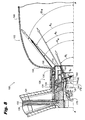
- the central cavity of the inner air swirler defines a converging diverging flow path. The converging portion of the converging diverging flow path defines a throat of the inner air swirler, which can advantageously be upstream of fuel injection points of the inner fuel injector.
- the throat of the converging diverging flow path can define a stagnation point in the central cavity, and another stagnation point can be defined at an upstream end of the central cavity.
- the inner air swirler can include an inlet dome with radial swirl slots defined therethrough for introducing a swirling air flow into the central cavity. It is also contemplated that the recirculation product injection nozzle can include an inner intermediate air passage between the inner air swirler and the inner fuel injector.
- the inner air swirler can include a radial air swirler defined therethrough in a downstream portion thereof for passage of air from the inner intermediate air passage into the central cavity.
- An inner air swirler is mounted radially inboard of the diffuser ring.
- the inner air swirler includes a central cavity defined therein along the central axis.
- the inner air swirler is configured and adapted to recirculate combustion products as described above.
- the inner air swirler includes a plurality of apertures, each having a respective fuel injection port of the inner fuel injector ring proximate thereto for injecting fuel through a layer of compressor discharge air from the inner air swirler into the inner recirculation zone.
- the step of injecting fuel from an inner fuel injector includes injecting fuel through a layer of swirling compressor discharge air between the inner fuel injector and the inner recirculation zone.
- the step of injecting fuel from an outer fuel injector can include injecting fuel in a direction away from compressor discharge air from the outer air swirler and into the outer recirculation zone.
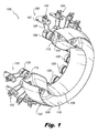
- FIG. 1 a partial view of an exemplary embodiment of a combustion system in accordance with the invention is shown in Fig. 1 and is designated generally by reference character 100.
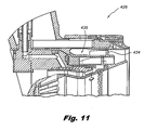
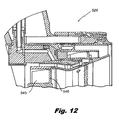
- FIGs. 2-12 Other embodiments of combustion systems in accordance with the invention, or aspects thereof, are provided in Figs. 2-12 , as will be described.
- the systems of the invention can be used to inject and combust fuel and air in a distributed manner using recirculated combustion products to improve emissions and lean bum stability for gas turbine engines and the like.
- Aero gas turbine engines have progressively been designed to operate at leaner fuel-to-air ratios in order to reduce emissions of NO x , and at higher pressure to increase efficiency.
- the trend toward higher pressure, lean combustion has been impeded by operability concerns.
- Very lean combustion has proven to be unstable and generally not well suited for aircraft engines.
- a very stable form of combustion has been used in industrial furnaces in Europe, operating at very lean conditions with fuel reacting with a very high temperature oxidizer at very high levels of turbulence in a distributed reaction zone.
- the high turbulence that is required to dissipate coherent flow structures and distribute the flame over a large volume requires the oxidizer temperature to be high to prevent the turbulence from extinguishing the flame by the high turbulent strain. Due to high flame strain and excessive dissipation of combustion radicals, the oxidizer temperature needs to be greater than approximately 1100°K. Such temperatures are significantly higher than typical gas turbine compressor discharge temperatures (T3) for even 40:1 compression ratio gas turbine engines.
- Distributed combustion also results in a substantially more homogeneous temperature distribution across the combustor than in systems with wrinkled laminar flames or flamelets in eddies. This is due to the completion of combustion prior to encountering the turbine and the lack of local combustion pockets being significantly richer or leaner than the average. An even temperature distribution reduces wear on turbine blades since there are no high temperature streaks, and little to no temperature gradient at the turbine inlet allows for higher turbine efficiency.
- the systems and methods of the invention provide a means of mixing fuel and oxidizer through a unique and indirect process in order to meet the requirements of distributed combustion in a gas turbine engine combustor.
- the primary requirements to obtain stable distributed combustion are high temperature oxidation and sufficiently rapid mixing such that distributed oxidization occurs without a discrete flame front.
- the temperature required about 1100°K or greater, exceeds compressor discharge temperature (T3) for typical gas turbine engines.
- This invention includes a device for mixing compressor air with combustion gases to reduce oxidizer concentration and to increase oxidizer temperature such that volumetric distributed combustion occurs at very lean fuel-air mixtures.
- the device achieves mixing of inlet oxidizer and recirculated combustion gases within the confines af the combustor and fuel nozzle section of a gas turbine engine without the need for auxiliary ducting or large heat exchangers common in industrial process applications, and without needing to include a more unconventional reverse flow style combustor in a gas turbine engine.
- flame anchoring is a secondary function that is only utilized at equivalence ratios above which the distributed reaction occurs.
- the inventive device described herein primarily uses the swirl as a means of pumping large amounts of combustion products upstream of the fuel injection and internal to the device to be mixed with and heat the compressor air to sufficiently high temperatures as to promote stable, volumetric, distributed reaction.
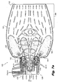
- a lip on the exit of the nozzle protruding aft from the most forward part of the combustion chamber in conjunction with the strong swirl also generates a significant outer recirculation zone of hot combustion gases that is greater in volume than that of the central/internal recirculation zone and important to achieving rapid homogeneous distribution of fuel.
- two fuel circuits exist, an inner fuel circuit and an outer fuel circuit, each having of a plurality of injection sites to reduce mixing lengths. Mixing between the inlet air and combustion products prior to fuel injection also results in a more dilute mixture of oxidizer with products that creates a leaner combustion environment extending auto-ignition delay of the reaction.
- Upstream stagnation point 174 near the wall of dome 178 is very stable since this point is relatively isolated from small pressure oscillations in combustor 102 far downstream.
- the recirculating flow in upstream zone 180 within central cavity 146 also helps pull downstream stagnation point 176 back into place if it is perturbed by downstream fluctuations.
- the recirculation downstream of throat 172 pulls stagnation point 176 back to throat 172 if perturbed from upstream.
- the stability of the stagnation points 174 and 176 is greater than that of traditional fuel nozzles.
Landscapes
- Engineering & Computer Science (AREA)
- Chemical & Material Sciences (AREA)
- Combustion & Propulsion (AREA)
- Mechanical Engineering (AREA)
- General Engineering & Computer Science (AREA)
Claims (15)
- Tuyère d'injection de produit de remise en circulation (126, 226, 326, 426, 526) comprenant :a) un carter de tuyère (128) comportant une extrémité d'admission (130) et une extrémité opposée d'évacuation (132), le carter de tuyère définissant un axe central (A) le long d'une direction de l'extrémité d'admission à l'extrémité d' évacuation ;b) un pulvérisateur d'air extérieur (134, 234, 334, 434) monté au carter de tuyère et configuré pour provoquer un tourbillon vers un flux d'air d'évacuation de compresseur à partir de l'amont de l'extrémité d'admission traversant le pulvérisateur d'air extérieur avec suffisamment de force de pulvérisation pour remettre en circulation des produits de combustion à partir de l'aval de l'extrémité d'évacuation jusqu'à une zone extérieure de remise en circulation (162) à proximité de l'extrémité extérieure ;c) un injecteur extérieur de carburant (136, 236, 336) monté à proximité du pulvérisateur d'air extérieur et définissant un ensemble d'orifices d'évacuation (158, 358) orientés pour diriger l'injection d'un jet de carburant selon un angle écarté de l'axe central en aval de la tuyère dans la zone extérieure de remise en circulation ;d) un pulvérisateur d'air intérieur (144, 244, 334, 545) monté radialement à l'intérieur du pulvérisateur d'air extérieur et de l'injecteur extérieur de carburant par rapport à l'axe central, le pulvérisateur d'air intérieur comprenant une cavité centrale (146) définie dans celui-ci le long de l'axe central et configurée et conçue pour produire un tourbillon vers un flux d'air d'évacuation de compresseur de l'amont de l'extrémité d'admission traversant le pulvérisateur d'air intérieur avec suffisamment de force de pulvérisation pour remettre en circulation des produits de combustion provenant de l'aval de l'extrémité de sortie dans une zone intérieure de remise en circulation (168) radialement vers l'intérieur de la zone extérieure de remise en circulation et s'étendant dans la cavité centrale ; ete) un injecteur intérieur de carburant (148, 248, 348) monté radialement à l'extérieur de la cavité centrale du pulvérisateur d'air intérieur et configuré pour injecter un jet de carburant à travers une couche d'air d'évacuation de compresseur à partir du pulvérisateur d'air intérieur et dans la zone intérieure de remise en circulation.
- Tuyère d'injection de produit de remise en circulation (126) selon la revendication 1, dans laquelle la cavité centrale (146) du pulvérisateur d'air intérieur définit une voie d'écoulement convergente divergente, la partie convergente de la voie d'écoulement convergente divergente définissant une gorge (172) du pulvérisateur d'air intérieur (144), et la gorge se trouvant en amont des points d'injection de carburant (156) de l'injecteur intérieur de carburant (148).
- Tuyère d'injection de produit de remise en circulation (126) selon la revendication 1, dans laquelle soit a) soit b) au moins :a) la tuyère d'injection de produit de remise en circulation comprend en outre un passage intermédiaire intérieur pour l'air (181) entre le pulvérisateur d'air intérieur (144) et l'injecteur intérieur de carburant (148), le pulvérisateur d'air intérieur comprenant un pulvérisateur radial d'air (179) défini à travers lui dans une partie aval de celui-ci, pour le passage d'air à partir du passage intérieur d'air intermédiaire jusqu'à la cavité centrale (146) ;b) le pulvérisateur d'air intérieur comprend un dôme d'admission (178) doté de fentes radiales de pulvérisation (145) définies à travers lui pour introduire un flux d'air tourbillonnant dans la cavité centrale.
- Tuyère d'injection de produit de remise en circulation (126, 226, 326) selon la revendication 1, dans laquelle la tuyère d'injection de produit de remise en circulation comprend en outre un pulvérisateur d'air intermédiaire (182, 282, 382) disposé entre le pulvérisateur d'air extérieur (134, 234, 334) et l'injecteur intérieur de carburant (148, 248, 348), le pulvérisateur d'air intermédiaire ayant une sortie divergente configurée pour diriger l'air de sortie du pulvérisateur d'air extérieur et le pulvérisateur d'air intermédiaire selon un angle divergent par rapport à l'axe central (A), et
en option :la sortie divergente du pulvérisateur d'air intérieur a une surface intérieure qui affleure avec la cavité centrale (146) du pulvérisateur d'air intérieur (144, 244, 344). - Tuyère d'injection de produit de remise en circulation (126, 226, 326) selon la revendication 1, dans laquelle au moins l'une des choses suivantes est vérifiée :a) l'injecteur extérieur de carburant (136, 236, 336) est configuré et conçu pour injecter un jet de carburant dans une direction radialement divergente par rapport à l'axe central (A) ;b) l'injecteur intérieur de carburant (148, 248, 348) est configuré et conçu pour injecter un jet de carburant dans une direction radialement convergente par rapport à l'axe central.
- Tuyère d'injection de produit de remise en circulation (126, 226, 326) selon la revendication 1, dans laquelle le carter de tuyère (128) contient une surface aval à forme de filetage (165, 265, 365) configurée et conçue pour diriger des produits de combustion remis en circulation dans la zone extérieure de remise en circulation (162) dans un sens orienté vers l'aval.
- Tuyère d'injection de produit de remise en circulation (126, 226, 326) selon la revendication 1, comprenant en outre :une bague de diffusion montée radialement à l'intérieur de l'injecteur extérieur de carburant (134, 234, 334) et contenant une sortie tronconique divergente (184, 284, 384) configurée pour diriger l'air d'évacuation directe du compresseur du pulvérisateur radial du pulvérisateur d'air extérieur dans une direction divergente par rapport à l'axe central (A),l'injecteur intérieur de carburant (148, 248, 348) étant une bague montée radialement à l'intérieur de la bague collectrice et comportant une pluralité d'orifices d'injection de carburant dirigés vers l'intérieur (160), et le pulvérisateur d'air intérieur (144, 244, 344) étant monté radialement à l'intérieur de la bague de diffusion, le pulvérisateur d'air intérieur comprenant un ensemble d'ouvertures (179) dont chacun contient un orifice respectif d'injection de carburant de l'injecteur intérieur de carburant proche de lui, permettant d'injecter du carburant à travers une couche d'air d'évacuation du compresseur à partir du pulvérisateur d'air intérieur dans la zone intérieure de remise en circulation (168), etle pulvérisateur d'air extérieur étant une bague qui contient un pulvérisateur radial, et le l'injecteur extérieur de carburant (136, 236, 336) étant une bague montée dans une cavité d'isolement du pulvérisateur d'air extérieur en aval du pulvérisateur radial.
- Tuyère d'injection de produit de remise en circulation (126) selon la revendication 7, dans laquelle la cavité centrale (146) du pulvérisateur d'air intérieur (144) comprend une gorge (172) qui définit une voie d'écoulement convergente divergente avec un premier point de stagnation (176) défini au niveau d'une extrémité amont de la cavité centrale, et un deuxième point de stagnation (174) défini au niveau de la gorge.
- Tuyère d'injection de produit de remise en circulation (126) selon la revendication 7, dans laquelle au moins soit a) soit b) :a) la tuyère d'injection de produit de remise en circulation comprend en outre un passage d'air intermédiaire intérieur (181) entre le pulvérisateur d'air intérieur (144) et l'injecteur intérieur de carburant (148), le pulvérisateur d'air intérieur contenant un pulvérisateur radial d'air (179) défini à travers lui dans une partie aval de celui-ci pour le passage d'air du passage d'air intermédiaire intérieur et jusqu'à la cavité centrale (146) ;b) le pulvérisateur d'air intérieur contient un dôme d'admission (178) d'air doté de fentes radiales de pulvérisation (145) défini à travers lui pour introduire un flux d'air pulvérisé dans la cavité centrale.
- Tuyère d'injection de produit de remise en circulation (126, 226, 326) selon la revendication 7, comprenant en outre un pulvérisateur d'air intermédiaire (182, 282, 382) disposé entre le pulvérisateur d'air extérieur (134, 234, 334) et l'injecteur intérieur de carburant (148, 248, 348), le pulvérisateur d'air intermédiaire ayant une sortie divergente configurée pour diriger l'air de sortie du pulvérisateur d'air extérieur et le pulvérisateur d'air intermédiaire selon un angle divergent par rapport à l'axe central (A), et la sortie divergente du pulvérisateur d'air intérieur ayant une surface intérieure qui affleure avec la cavité centrale (146) du pulvérisateur d'air intérieur (144, 244, 344).
- Tuyère d'injection de produit de remise en circulation (126, 226, 326) selon la revendication 10, dans laquelle l'injecteur extérieur de carburant (136, 236, 336) est configuré et conçu pour injecter un jet de carburant dans une direction radialement divergente par rapport à l'axe central (A).
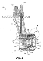
- Système de combustion (100) destiné à un moteur de turbine, comprenant :a) un corps annulaire de chambre de combustion (102) comportant une paroi amont (104) dotée de parois radialement intérieures et extérieures (106, 108) s'étendant à partir de celui-ci avec une ouverture aval (110) entre les parois radialement intérieure et extérieure opposées à la paroi amont pour acheminer des produits de combustion jusqu'à une turbine, la paroi amont comprenant une pluralité d'orifices d'injecteur (112) ; etb) une pluralité d'injecteurs (120) dont chacun est monté à un orifice respectif d'injecteur du corps de chambre de combustion, chaque injecteur comprenant une entrée de carburant (122), un bras d'alimentation d'injecteur (124) s'étendant à partir de l'entrée de carburant et une tuyère d'injection de produit de remise en circulation (126, 226, 326, 426, 526) selon la revendication 1 dépendant du bras d'alimentation en communication fluidique avec l'entrée de carburant, afin d'injecter du carburant et de l'air d'évacuation de compresseur dans le corps de chambre de combustion.
- Système de combustion (100) selon la revendication 12, dans lequel le corps de chambre de combustion (102) et les injecteurs (120) sont configurés et conçus pour introduire sensiblement l'ensemble du carburant et de l'air d'évacuation du compresseur dans le corps de chambre de combustion à travers les injecteurs.
- Procédé d'acheminement de produits de combustion jusqu'à une turbine dans un moteur de turbine à gaz, comprenant :a) la formation d'une zone extérieure de remise en circulation (162) de produits de combustion de remise en circulation dans une chambre à combustion (102) et la formation d'une zone intérieure de remise en circulation (168) à l'intérieur de la zone intérieure de remise en circulation, les zones intérieure et extérieure de remise en circulation étant formées par production d'un tourbillon dans l'air d'évacuation de compresseur traversant un pulvérisateur d'air extérieur (134, 234, 334, 434) et un pulvérisateur d'air intérieur (144, 244, 344, 545) radialement à l'intérieur du pulvérisateur d'air extérieur ;b) l'injection de carburant à partir d'un injecteur extérieur de carburant (136, 236, 336) à travers une pluralité d'orifices de sortie (158) orientés selon un angle dans une direction aval en aval de l'injecteur de carburant, directement dans la zone extérieure de remise en circulation ; etc) l'injection de carburant à partir d'un injecteur intérieur de carburant (148, 248, 348) dans la zone intérieure de remise en circulation.
- Procédé selon la revendication 14, dans lequel au moins soit a) soit b) :a) l'étape d'injection de carburant à partir d'un injecteur intérieur de carburant (148, 248, 348) comprend l'injection de carburant à travers une couche d'air d'évacuation de compresseur de pulvérisation entre l'injecteur intérieur de carburant et la zone intérieure de remise en circulation (168) ;b) l'étape d'injection de carburant à partir d'un injecteur extérieur de carburant (136, 236, 336) comprend l'injection de carburant dans une direction d'éloignement de l'air d'évacuation du compresseur à partir du pulvérisateur d'air extérieur (134, 234, 334, 434) et dans la zone extérieure de remise en circulation (162).
Applications Claiming Priority (2)
| Application Number | Priority Date | Filing Date | Title |
|---|---|---|---|
| US201161454356P | 2011-03-18 | 2011-03-18 | |
| US13/083,298 US8925325B2 (en) | 2011-03-18 | 2011-04-08 | Recirculating product injection nozzle |
Publications (2)
| Publication Number | Publication Date |
|---|---|
| EP2500641A1 EP2500641A1 (fr) | 2012-09-19 |
| EP2500641B1 true EP2500641B1 (fr) | 2014-11-05 |
Family
ID=45937132
Family Applications (1)
| Application Number | Title | Priority Date | Filing Date |
|---|---|---|---|
| EP12250061.4A Active EP2500641B1 (fr) | 2011-03-18 | 2012-03-16 | Buse d'injection de produit de recirculation |
Country Status (2)
| Country | Link |
|---|---|
| US (1) | US8925325B2 (fr) |
| EP (1) | EP2500641B1 (fr) |
Cited By (1)
| Publication number | Priority date | Publication date | Assignee | Title |
|---|---|---|---|---|
| CN108980893A (zh) * | 2018-07-09 | 2018-12-11 | 西北工业大学 | 孔型多点直接喷射旋流器及孔型多点直接喷射头部结构 |
Families Citing this family (49)
| Publication number | Priority date | Publication date | Assignee | Title |
|---|---|---|---|---|
| JP5773342B2 (ja) * | 2011-06-03 | 2015-09-02 | 川崎重工業株式会社 | 燃料噴射装置 |
| JP5772245B2 (ja) | 2011-06-03 | 2015-09-02 | 川崎重工業株式会社 | 燃料噴射装置 |
| US9188063B2 (en) | 2011-11-03 | 2015-11-17 | Delavan Inc. | Injectors for multipoint injection |
| US9447974B2 (en) * | 2012-09-13 | 2016-09-20 | United Technologies Corporation | Light weight swirler for gas turbine engine combustor and a method for lightening a swirler for a gas turbine engine |
| US10161633B2 (en) * | 2013-03-04 | 2018-12-25 | Delavan Inc. | Air swirlers |
| US9958161B2 (en) | 2013-03-12 | 2018-05-01 | Pratt & Whitney Canada Corp. | Combustor for gas turbine engine |
| US9366187B2 (en) * | 2013-03-12 | 2016-06-14 | Pratt & Whitney Canada Corp. | Slinger combustor |
| US9541292B2 (en) | 2013-03-12 | 2017-01-10 | Pratt & Whitney Canada Corp. | Combustor for gas turbine engine |
| US9127843B2 (en) | 2013-03-12 | 2015-09-08 | Pratt & Whitney Canada Corp. | Combustor for gas turbine engine |
| US9228747B2 (en) | 2013-03-12 | 2016-01-05 | Pratt & Whitney Canada Corp. | Combustor for gas turbine engine |
| EP3011231B1 (fr) | 2013-06-18 | 2019-10-30 | Woodward, Inc. | Ensemble de chambre de combustion de turbine à gaz |
| US9835089B2 (en) * | 2013-06-28 | 2017-12-05 | General Electric Company | System and method for a fuel nozzle |
| EP3036482B1 (fr) * | 2013-08-20 | 2020-10-21 | United Technologies Corporation | Système et appareil de buse à deux combustibles |
| EP3039343B8 (fr) * | 2013-08-30 | 2021-03-31 | Raytheon Technologies Corporation | Injecteur de bicarburant ayant une injection de gaz axial tourbillonnant pour une turbine à gaz et procédé associé |
| US9482433B2 (en) * | 2013-11-11 | 2016-11-01 | Woodward, Inc. | Multi-swirler fuel/air mixer with centralized fuel injection |
| US10731861B2 (en) * | 2013-11-18 | 2020-08-04 | Raytheon Technologies Corporation | Dual fuel nozzle with concentric fuel passages for a gas turbine engine |
| WO2015116360A1 (fr) * | 2014-01-30 | 2015-08-06 | United Technologies Corporation | Flux de refroidissement pour un panneau principal dans une chambre de combustion de moteur à turbine à gaz |
| US9897321B2 (en) * | 2015-03-31 | 2018-02-20 | Delavan Inc. | Fuel nozzles |
| US10385809B2 (en) | 2015-03-31 | 2019-08-20 | Delavan Inc. | Fuel nozzles |
| US10001281B2 (en) * | 2015-04-17 | 2018-06-19 | General Electric Company | Fuel nozzle with dual-staged main circuit |
| US10184665B2 (en) | 2015-06-10 | 2019-01-22 | General Electric Company | Prefilming air blast (PAB) pilot having annular splitter surrounding a pilot fuel injector |
| US9927126B2 (en) | 2015-06-10 | 2018-03-27 | General Electric Company | Prefilming air blast (PAB) pilot for low emissions combustors |
| FR3039254B1 (fr) * | 2015-07-24 | 2021-10-08 | Snecma | Chambre de combustion comportant des dispositifs d'injection additionnels debouchant directement dans les zones de recirculation de coin, turbomachine la comprenant, et procede d'alimentation en carburant de celle-ci |
| US10364751B2 (en) * | 2015-08-03 | 2019-07-30 | Delavan Inc | Fuel staging |
| US10047959B2 (en) * | 2015-12-29 | 2018-08-14 | Pratt & Whitney Canada Corp. | Fuel injector for fuel spray nozzle |
| GB2548585B (en) * | 2016-03-22 | 2020-05-27 | Rolls Royce Plc | A combustion chamber assembly |
| US10502425B2 (en) * | 2016-06-03 | 2019-12-10 | General Electric Company | Contoured shroud swirling pre-mix fuel injector assembly |
| US10247106B2 (en) * | 2016-06-15 | 2019-04-02 | General Electric Company | Method and system for rotating air seal with integral flexible heat shield |
| US20180058404A1 (en) * | 2016-08-29 | 2018-03-01 | Parker-Hannifin Corporation | Fuel injector assembly with wire mesh damper |
| US11149952B2 (en) * | 2016-12-07 | 2021-10-19 | Raytheon Technologies Corporation | Main mixer in an axial staged combustor for a gas turbine engine |
| WO2019132326A1 (fr) * | 2017-12-26 | 2019-07-04 | 한화에어로스페이스 주식회사 | Mélangeur pour chambre de combustion |
| US11175045B2 (en) * | 2018-01-04 | 2021-11-16 | General Electric Company | Fuel nozzle for gas turbine engine combustor |
| US10788214B2 (en) * | 2018-04-10 | 2020-09-29 | Delavan Inc. | Fuel injectors for turbomachines having inner air swirling |
| FR3084446B1 (fr) * | 2018-07-25 | 2024-02-02 | Safran Aircraft Engines | Chambre de combustion monobloc |
| CZ308246B6 (cs) * | 2018-09-26 | 2020-03-18 | První Brněnská Strojírna Velká Bíteš, A.S. | Montážní sestava obtokových palivových trysek pro malý turbínový motor s prstencovou spalovací komorou a obtoková palivová tryska pro ni |
| US11253823B2 (en) | 2019-03-29 | 2022-02-22 | Delavan Inc. | Mixing nozzles |
| US11608783B2 (en) | 2020-11-04 | 2023-03-21 | Delavan, Inc. | Surface igniter cooling system |
| US11635027B2 (en) | 2020-11-18 | 2023-04-25 | Collins Engine Nozzles, Inc. | Fuel systems for torch ignition devices |
| GB202019219D0 (en) | 2020-12-07 | 2021-01-20 | Rolls Royce Plc | Lean burn combustor |
| GB202019222D0 (en) * | 2020-12-07 | 2021-01-20 | Rolls Royce Plc | Lean burn combustor |
| US11421602B2 (en) * | 2020-12-16 | 2022-08-23 | Delavan Inc. | Continuous ignition device exhaust manifold |
| US12092333B2 (en) | 2020-12-17 | 2024-09-17 | Collins Engine Nozzles, Inc. | Radially oriented internally mounted continuous ignition device |
| US20220364511A1 (en) * | 2021-05-11 | 2022-11-17 | General Electric Company | Integral fuel-nozzle and mixer with angled jet-in-crossflow fuel injection |
| US11773784B2 (en) * | 2021-10-12 | 2023-10-03 | Collins Engine Nozzles, Inc. | Fuel injectors with torch ignitors |
| FR3135114A1 (fr) * | 2022-05-02 | 2023-11-03 | Safran | Procede d’injection de melange hydrogene-air pour bruleur de turbomachine |
| JP2024080498A (ja) * | 2022-12-02 | 2024-06-13 | トヨタ自動車株式会社 | 水素ガスタービンに適した燃焼器及びその燃焼ノズル |
| CN121620666A (zh) * | 2023-08-14 | 2026-03-06 | 气体产品与化学公司 | 燃烧器、操作方法和燃烧设备 |
| US12338774B1 (en) * | 2024-04-11 | 2025-06-24 | General Electric Company | Fuel injector manifold having a variable fuel flow system for a turbine engine |
| US20250361839A1 (en) * | 2024-05-23 | 2025-11-27 | Solar Turbines Incorporated | Fuel injector and methods of use |
Citations (1)
| Publication number | Priority date | Publication date | Assignee | Title |
|---|---|---|---|---|
| EP2497922A2 (fr) * | 2011-03-10 | 2012-09-12 | Delavan Inc. | Systèmes et procédés de refroidissement d'un injecteur de carburant à air comprimé étagé |
Family Cites Families (19)
| Publication number | Priority date | Publication date | Assignee | Title |
|---|---|---|---|---|
| USRE23149E (en) | 1949-09-20 | Combustion burner | ||
| IT1111808B (it) * | 1978-03-28 | 1986-01-13 | Rolls Royce | Perfezionamenti apportati ai dispositivi di combustione di motori a turbina a gas |
| US4977740A (en) * | 1989-06-07 | 1990-12-18 | United Technologies Corporation | Dual fuel injector |
| US5076061A (en) | 1989-12-15 | 1991-12-31 | Sundstrand Corporation | Stored energy combustor |
| GB9023004D0 (en) | 1990-10-23 | 1990-12-05 | Rolls Royce Plc | A gas turbine engine combustion chamber and a method of operating a gas turbine engine combustion chamber |
| GB9410233D0 (en) | 1994-05-21 | 1994-07-06 | Rolls Royce Plc | A gas turbine engine combustion chamber |
| CH695793A5 (de) | 2001-10-01 | 2006-08-31 | Alstom Technology Ltd | Verbrennungsverfahren, insbesondere für Verfahren zur Erzeugung von elektrischem Strom und/oder von Wärme. |
| DE10217913B4 (de) | 2002-04-23 | 2004-10-07 | WS Wärmeprozesstechnik GmbH | Gasturbine mit Brennkammer zur flammenlosen Oxidation |
| US7565803B2 (en) | 2005-07-25 | 2009-07-28 | General Electric Company | Swirler arrangement for mixer assembly of a gas turbine engine combustor having shaped passages |
| US7581396B2 (en) | 2005-07-25 | 2009-09-01 | General Electric Company | Mixer assembly for combustor of a gas turbine engine having a plurality of counter-rotating swirlers |
| US7464553B2 (en) | 2005-07-25 | 2008-12-16 | General Electric Company | Air-assisted fuel injector for mixer assembly of a gas turbine engine combustor |
| US7762073B2 (en) * | 2006-03-01 | 2010-07-27 | General Electric Company | Pilot mixer for mixer assembly of a gas turbine engine combustor having a primary fuel injector and a plurality of secondary fuel injection ports |
| US20080083224A1 (en) | 2006-10-05 | 2008-04-10 | Balachandar Varatharajan | Method and apparatus for reducing gas turbine engine emissions |
| FR2911667B1 (fr) | 2007-01-23 | 2009-10-02 | Snecma Sa | Systeme d'injection de carburant a double injecteur. |
| CA2595061C (fr) | 2007-07-23 | 2014-10-07 | General Electric Company | Methode et appareil pour la commande active de l'ecoulement de carburant a un melangeur d'une chambre de combustion d'une turbine a gaz |
| DE102007043626A1 (de) * | 2007-09-13 | 2009-03-19 | Rolls-Royce Deutschland Ltd & Co Kg | Gasturbinenmagerbrenner mit Kraftstoffdüse mit kontrollierter Kraftstoffinhomogenität |
| EP2107309A1 (fr) * | 2008-04-01 | 2009-10-07 | Siemens Aktiengesellschaft | Diffuseurs dans un brûleur |
| EP2107300A1 (fr) * | 2008-04-01 | 2009-10-07 | Siemens Aktiengesellschaft | Ensemble de tourbillonnement avec injecteur à gaz |
| US8667800B2 (en) * | 2009-05-13 | 2014-03-11 | Delavan Inc. | Flameless combustion systems for gas turbine engines |
-
2011
- 2011-04-08 US US13/083,298 patent/US8925325B2/en active Active
-
2012
- 2012-03-16 EP EP12250061.4A patent/EP2500641B1/fr active Active
Patent Citations (1)
| Publication number | Priority date | Publication date | Assignee | Title |
|---|---|---|---|---|
| EP2497922A2 (fr) * | 2011-03-10 | 2012-09-12 | Delavan Inc. | Systèmes et procédés de refroidissement d'un injecteur de carburant à air comprimé étagé |
Cited By (1)
| Publication number | Priority date | Publication date | Assignee | Title |
|---|---|---|---|---|
| CN108980893A (zh) * | 2018-07-09 | 2018-12-11 | 西北工业大学 | 孔型多点直接喷射旋流器及孔型多点直接喷射头部结构 |
Also Published As
| Publication number | Publication date |
|---|---|
| EP2500641A1 (fr) | 2012-09-19 |
| US8925325B2 (en) | 2015-01-06 |
| US20120234013A1 (en) | 2012-09-20 |
Similar Documents
| Publication | Publication Date | Title |
|---|---|---|
| EP2500641B1 (fr) | Buse d'injection de produit de recirculation | |
| US5511375A (en) | Dual fuel mixer for gas turbine combustor | |
| US5251447A (en) | Air fuel mixer for gas turbine combustor | |
| US6993916B2 (en) | Burner tube and method for mixing air and gas in a gas turbine engine | |
| EP0500256B1 (fr) | Mélangeur air/combustible pour chambre de combustion de turbine à gaz | |
| US5590529A (en) | Air fuel mixer for gas turbine combustor | |
| US5351477A (en) | Dual fuel mixer for gas turbine combustor | |
| US5613363A (en) | Air fuel mixer for gas turbine combustor | |
| US7926282B2 (en) | Pure air blast fuel injector | |
| CN103776060B (zh) | 再热喷燃器布置 | |
| US8667800B2 (en) | Flameless combustion systems for gas turbine engines | |
| US5865024A (en) | Dual fuel mixer for gas turbine combustor | |
| JP5746091B2 (ja) | ローブスワーラ | |
| CN110631049B (zh) | 燃气轮机柔和燃烧室 | |
| US20140096502A1 (en) | Burner for a gas turbine | |
| CN102032569A (zh) | 燃烧器 | |
| US20100192583A1 (en) | Non-rotational stabilization of the flame of a premixing burner | |
| JP2009133599A (ja) | 燃焼システム内における逆火/保炎を減少させるのを可能にする方法及びシステム | |
| CN101377305A (zh) | 带径向分级流通道的预混合器和混合空气及燃气的方法 | |
| JP2011058775A (ja) | ガスタービン燃焼器 | |
| JP2011002221A (ja) | 予混合ノズルにおける合成ガス/天然ガス乾式低NOxのための複数燃料回路 | |
| EP4056902B1 (fr) | Mélangeur de carburant | |
| US11846425B2 (en) | Dual fuel gas turbine engine pilot nozzles | |
| CN102345879A (zh) | 燃料喷嘴及包括该燃料喷嘴的组件和燃气涡轮机 | |
| JP2008128631A (ja) | 空気と燃料の混合物を噴射する装置と、このような装置を備える燃焼チャンバ及びターボ機械 |
Legal Events
| Date | Code | Title | Description |
|---|---|---|---|
| PUAI | Public reference made under article 153(3) epc to a published international application that has entered the european phase |
Free format text: ORIGINAL CODE: 0009012 |
|
| 17P | Request for examination filed |
Effective date: 20120326 |
|
| AK | Designated contracting states |
Kind code of ref document: A1 Designated state(s): AL AT BE BG CH CY CZ DE DK EE ES FI FR GB GR HR HU IE IS IT LI LT LU LV MC MK MT NL NO PL PT RO RS SE SI SK SM TR |
|
| AX | Request for extension of the european patent |
Extension state: BA ME |
|
| 17Q | First examination report despatched |
Effective date: 20131007 |
|
| GRAP | Despatch of communication of intention to grant a patent |
Free format text: ORIGINAL CODE: EPIDOSNIGR1 |
|
| INTG | Intention to grant announced |
Effective date: 20140812 |
|
| RIN1 | Information on inventor provided before grant (corrected) |
Inventor name: SHORT, JOHN E. Inventor name: OVERMAN, NICHOLAS R. |
|
| GRAS | Grant fee paid |
Free format text: ORIGINAL CODE: EPIDOSNIGR3 |
|
| GRAA | (expected) grant |
Free format text: ORIGINAL CODE: 0009210 |
|
| AK | Designated contracting states |
Kind code of ref document: B1 Designated state(s): AL AT BE BG CH CY CZ DE DK EE ES FI FR GB GR HR HU IE IS IT LI LT LU LV MC MK MT NL NO PL PT RO RS SE SI SK SM TR |
|
| REG | Reference to a national code |
Ref country code: GB Ref legal event code: FG4D |
|
| REG | Reference to a national code |
Ref country code: CH Ref legal event code: EP |
|
| REG | Reference to a national code |
Ref country code: AT Ref legal event code: REF Ref document number: 694839 Country of ref document: AT Kind code of ref document: T Effective date: 20141115 |
|
| REG | Reference to a national code |
Ref country code: IE Ref legal event code: FG4D |
|
| REG | Reference to a national code |
Ref country code: DE Ref legal event code: R096 Ref document number: 602012003672 Country of ref document: DE Effective date: 20141224 |
|
| REG | Reference to a national code |
Ref country code: AT Ref legal event code: MK05 Ref document number: 694839 Country of ref document: AT Kind code of ref document: T Effective date: 20141105 |
|
| REG | Reference to a national code |
Ref country code: NL Ref legal event code: VDEP Effective date: 20141105 |
|
| REG | Reference to a national code |
Ref country code: LT Ref legal event code: MG4D |
|
| PG25 | Lapsed in a contracting state [announced via postgrant information from national office to epo] |
Ref country code: PT Free format text: LAPSE BECAUSE OF FAILURE TO SUBMIT A TRANSLATION OF THE DESCRIPTION OR TO PAY THE FEE WITHIN THE PRESCRIBED TIME-LIMIT Effective date: 20150305 Ref country code: ES Free format text: LAPSE BECAUSE OF FAILURE TO SUBMIT A TRANSLATION OF THE DESCRIPTION OR TO PAY THE FEE WITHIN THE PRESCRIBED TIME-LIMIT Effective date: 20141105 Ref country code: LT Free format text: LAPSE BECAUSE OF FAILURE TO SUBMIT A TRANSLATION OF THE DESCRIPTION OR TO PAY THE FEE WITHIN THE PRESCRIBED TIME-LIMIT Effective date: 20141105 Ref country code: IS Free format text: LAPSE BECAUSE OF FAILURE TO SUBMIT A TRANSLATION OF THE DESCRIPTION OR TO PAY THE FEE WITHIN THE PRESCRIBED TIME-LIMIT Effective date: 20150305 Ref country code: FI Free format text: LAPSE BECAUSE OF FAILURE TO SUBMIT A TRANSLATION OF THE DESCRIPTION OR TO PAY THE FEE WITHIN THE PRESCRIBED TIME-LIMIT Effective date: 20141105 Ref country code: NL Free format text: LAPSE BECAUSE OF FAILURE TO SUBMIT A TRANSLATION OF THE DESCRIPTION OR TO PAY THE FEE WITHIN THE PRESCRIBED TIME-LIMIT Effective date: 20141105 Ref country code: NO Free format text: LAPSE BECAUSE OF FAILURE TO SUBMIT A TRANSLATION OF THE DESCRIPTION OR TO PAY THE FEE WITHIN THE PRESCRIBED TIME-LIMIT Effective date: 20150205 |
|
| PG25 | Lapsed in a contracting state [announced via postgrant information from national office to epo] |
Ref country code: PL Free format text: LAPSE BECAUSE OF FAILURE TO SUBMIT A TRANSLATION OF THE DESCRIPTION OR TO PAY THE FEE WITHIN THE PRESCRIBED TIME-LIMIT Effective date: 20141105 Ref country code: GR Free format text: LAPSE BECAUSE OF FAILURE TO SUBMIT A TRANSLATION OF THE DESCRIPTION OR TO PAY THE FEE WITHIN THE PRESCRIBED TIME-LIMIT Effective date: 20150206 Ref country code: RS Free format text: LAPSE BECAUSE OF FAILURE TO SUBMIT A TRANSLATION OF THE DESCRIPTION OR TO PAY THE FEE WITHIN THE PRESCRIBED TIME-LIMIT Effective date: 20141105 Ref country code: AT Free format text: LAPSE BECAUSE OF FAILURE TO SUBMIT A TRANSLATION OF THE DESCRIPTION OR TO PAY THE FEE WITHIN THE PRESCRIBED TIME-LIMIT Effective date: 20141105 Ref country code: SE Free format text: LAPSE BECAUSE OF FAILURE TO SUBMIT A TRANSLATION OF THE DESCRIPTION OR TO PAY THE FEE WITHIN THE PRESCRIBED TIME-LIMIT Effective date: 20141105 Ref country code: LV Free format text: LAPSE BECAUSE OF FAILURE TO SUBMIT A TRANSLATION OF THE DESCRIPTION OR TO PAY THE FEE WITHIN THE PRESCRIBED TIME-LIMIT Effective date: 20141105 Ref country code: CY Free format text: LAPSE BECAUSE OF FAILURE TO SUBMIT A TRANSLATION OF THE DESCRIPTION OR TO PAY THE FEE WITHIN THE PRESCRIBED TIME-LIMIT Effective date: 20141105 Ref country code: HR Free format text: LAPSE BECAUSE OF FAILURE TO SUBMIT A TRANSLATION OF THE DESCRIPTION OR TO PAY THE FEE WITHIN THE PRESCRIBED TIME-LIMIT Effective date: 20141105 |
|
| PG25 | Lapsed in a contracting state [announced via postgrant information from national office to epo] |
Ref country code: DK Free format text: LAPSE BECAUSE OF FAILURE TO SUBMIT A TRANSLATION OF THE DESCRIPTION OR TO PAY THE FEE WITHIN THE PRESCRIBED TIME-LIMIT Effective date: 20141105 Ref country code: EE Free format text: LAPSE BECAUSE OF FAILURE TO SUBMIT A TRANSLATION OF THE DESCRIPTION OR TO PAY THE FEE WITHIN THE PRESCRIBED TIME-LIMIT Effective date: 20141105 Ref country code: SK Free format text: LAPSE BECAUSE OF FAILURE TO SUBMIT A TRANSLATION OF THE DESCRIPTION OR TO PAY THE FEE WITHIN THE PRESCRIBED TIME-LIMIT Effective date: 20141105 Ref country code: CZ Free format text: LAPSE BECAUSE OF FAILURE TO SUBMIT A TRANSLATION OF THE DESCRIPTION OR TO PAY THE FEE WITHIN THE PRESCRIBED TIME-LIMIT Effective date: 20141105 |
|
| REG | Reference to a national code |
Ref country code: DE Ref legal event code: R097 Ref document number: 602012003672 Country of ref document: DE |
|
| PLBE | No opposition filed within time limit |
Free format text: ORIGINAL CODE: 0009261 |
|
| STAA | Information on the status of an ep patent application or granted ep patent |
Free format text: STATUS: NO OPPOSITION FILED WITHIN TIME LIMIT |
|
| 26N | No opposition filed |
Effective date: 20150806 |
|
| PG25 | Lapsed in a contracting state [announced via postgrant information from national office to epo] |
Ref country code: MC Free format text: LAPSE BECAUSE OF FAILURE TO SUBMIT A TRANSLATION OF THE DESCRIPTION OR TO PAY THE FEE WITHIN THE PRESCRIBED TIME-LIMIT Effective date: 20141105 Ref country code: LU Free format text: LAPSE BECAUSE OF FAILURE TO SUBMIT A TRANSLATION OF THE DESCRIPTION OR TO PAY THE FEE WITHIN THE PRESCRIBED TIME-LIMIT Effective date: 20150316 |
|
| REG | Reference to a national code |
Ref country code: CH Ref legal event code: PL |
|
| PG25 | Lapsed in a contracting state [announced via postgrant information from national office to epo] |
Ref country code: IT Free format text: LAPSE BECAUSE OF FAILURE TO SUBMIT A TRANSLATION OF THE DESCRIPTION OR TO PAY THE FEE WITHIN THE PRESCRIBED TIME-LIMIT Effective date: 20141105 |
|
| REG | Reference to a national code |
Ref country code: IE Ref legal event code: MM4A |
|
| PG25 | Lapsed in a contracting state [announced via postgrant information from national office to epo] |
Ref country code: IE Free format text: LAPSE BECAUSE OF NON-PAYMENT OF DUE FEES Effective date: 20150316 Ref country code: LI Free format text: LAPSE BECAUSE OF NON-PAYMENT OF DUE FEES Effective date: 20150331 Ref country code: CH Free format text: LAPSE BECAUSE OF NON-PAYMENT OF DUE FEES Effective date: 20150331 |
|
| REG | Reference to a national code |
Ref country code: FR Ref legal event code: PLFP Year of fee payment: 5 |
|
| PG25 | Lapsed in a contracting state [announced via postgrant information from national office to epo] |
Ref country code: SI Free format text: LAPSE BECAUSE OF FAILURE TO SUBMIT A TRANSLATION OF THE DESCRIPTION OR TO PAY THE FEE WITHIN THE PRESCRIBED TIME-LIMIT Effective date: 20141105 |
|
| PG25 | Lapsed in a contracting state [announced via postgrant information from national office to epo] |
Ref country code: RO Free format text: LAPSE BECAUSE OF FAILURE TO SUBMIT A TRANSLATION OF THE DESCRIPTION OR TO PAY THE FEE WITHIN THE PRESCRIBED TIME-LIMIT Effective date: 20141105 |
|
| PG25 | Lapsed in a contracting state [announced via postgrant information from national office to epo] |
Ref country code: MT Free format text: LAPSE BECAUSE OF FAILURE TO SUBMIT A TRANSLATION OF THE DESCRIPTION OR TO PAY THE FEE WITHIN THE PRESCRIBED TIME-LIMIT Effective date: 20141105 |
|
| REG | Reference to a national code |
Ref country code: FR Ref legal event code: PLFP Year of fee payment: 6 |
|
| PG25 | Lapsed in a contracting state [announced via postgrant information from national office to epo] |
Ref country code: SM Free format text: LAPSE BECAUSE OF FAILURE TO SUBMIT A TRANSLATION OF THE DESCRIPTION OR TO PAY THE FEE WITHIN THE PRESCRIBED TIME-LIMIT Effective date: 20141105 Ref country code: BG Free format text: LAPSE BECAUSE OF FAILURE TO SUBMIT A TRANSLATION OF THE DESCRIPTION OR TO PAY THE FEE WITHIN THE PRESCRIBED TIME-LIMIT Effective date: 20141105 Ref country code: HU Free format text: LAPSE BECAUSE OF FAILURE TO SUBMIT A TRANSLATION OF THE DESCRIPTION OR TO PAY THE FEE WITHIN THE PRESCRIBED TIME-LIMIT; INVALID AB INITIO Effective date: 20120316 |
|
| REG | Reference to a national code |
Ref country code: DE Ref legal event code: R082 Ref document number: 602012003672 Country of ref document: DE Representative=s name: SCHMITT-NILSON SCHRAUD WAIBEL WOHLFROM PATENTA, DE |
|
| PG25 | Lapsed in a contracting state [announced via postgrant information from national office to epo] |
Ref country code: TR Free format text: LAPSE BECAUSE OF FAILURE TO SUBMIT A TRANSLATION OF THE DESCRIPTION OR TO PAY THE FEE WITHIN THE PRESCRIBED TIME-LIMIT Effective date: 20141105 |
|
| PG25 | Lapsed in a contracting state [announced via postgrant information from national office to epo] |
Ref country code: BE Free format text: LAPSE BECAUSE OF FAILURE TO SUBMIT A TRANSLATION OF THE DESCRIPTION OR TO PAY THE FEE WITHIN THE PRESCRIBED TIME-LIMIT Effective date: 20141105 |
|
| REG | Reference to a national code |
Ref country code: FR Ref legal event code: PLFP Year of fee payment: 7 |
|
| PG25 | Lapsed in a contracting state [announced via postgrant information from national office to epo] |
Ref country code: MK Free format text: LAPSE BECAUSE OF FAILURE TO SUBMIT A TRANSLATION OF THE DESCRIPTION OR TO PAY THE FEE WITHIN THE PRESCRIBED TIME-LIMIT Effective date: 20141105 |
|
| PG25 | Lapsed in a contracting state [announced via postgrant information from national office to epo] |
Ref country code: AL Free format text: LAPSE BECAUSE OF FAILURE TO SUBMIT A TRANSLATION OF THE DESCRIPTION OR TO PAY THE FEE WITHIN THE PRESCRIBED TIME-LIMIT Effective date: 20141105 |
|
| P01 | Opt-out of the competence of the unified patent court (upc) registered |
Effective date: 20230530 |
|
| PGFP | Annual fee paid to national office [announced via postgrant information from national office to epo] |
Ref country code: GB Payment date: 20260220 Year of fee payment: 15 |
|
| PGFP | Annual fee paid to national office [announced via postgrant information from national office to epo] |
Ref country code: DE Payment date: 20260219 Year of fee payment: 15 |
|
| PGFP | Annual fee paid to national office [announced via postgrant information from national office to epo] |
Ref country code: FR Payment date: 20260219 Year of fee payment: 15 |