EP2500647A2 - Kohleflussteiler und Verteilervorrichtungen - Google Patents
Kohleflussteiler und Verteilervorrichtungen Download PDFInfo
- Publication number
- EP2500647A2 EP2500647A2 EP12156255A EP12156255A EP2500647A2 EP 2500647 A2 EP2500647 A2 EP 2500647A2 EP 12156255 A EP12156255 A EP 12156255A EP 12156255 A EP12156255 A EP 12156255A EP 2500647 A2 EP2500647 A2 EP 2500647A2
- Authority
- EP
- European Patent Office
- Prior art keywords
- divider
- inlet
- outlets
- flow splitter
- coal
- Prior art date
- Legal status (The legal status is an assumption and is not a legal conclusion. Google has not performed a legal analysis and makes no representation as to the accuracy of the status listed.)
- Granted
Links
- 239000003245 coal Substances 0.000 title claims description 78
- 239000002245 particle Substances 0.000 claims abstract description 33
- 238000011144 upstream manufacturing Methods 0.000 claims abstract description 16
- 239000012530 fluid Substances 0.000 claims abstract description 6
- 239000007787 solid Substances 0.000 claims abstract description 6
- 238000000034 method Methods 0.000 description 11
- 238000002485 combustion reaction Methods 0.000 description 6
- 239000000446 fuel Substances 0.000 description 3
- 238000007689 inspection Methods 0.000 description 2
- 239000000203 mixture Substances 0.000 description 2
- 238000012986 modification Methods 0.000 description 2
- 230000004048 modification Effects 0.000 description 2
- 230000008439 repair process Effects 0.000 description 2
- OKTJSMMVPCPJKN-UHFFFAOYSA-N Carbon Chemical compound [C] OKTJSMMVPCPJKN-UHFFFAOYSA-N 0.000 description 1
- 238000005299 abrasion Methods 0.000 description 1
- 229910052799 carbon Inorganic materials 0.000 description 1
- 239000002817 coal dust Substances 0.000 description 1
- 238000010276 construction Methods 0.000 description 1
- 238000007796 conventional method Methods 0.000 description 1
- 239000003344 environmental pollutant Substances 0.000 description 1
- 230000003628 erosive effect Effects 0.000 description 1
- 239000010881 fly ash Substances 0.000 description 1
- 230000003116 impacting effect Effects 0.000 description 1
- 238000012423 maintenance Methods 0.000 description 1
- 231100000719 pollutant Toxicity 0.000 description 1
- 238000005201 scrubbing Methods 0.000 description 1
- 238000003466 welding Methods 0.000 description 1
Images


Classifications
-
- F—MECHANICAL ENGINEERING; LIGHTING; HEATING; WEAPONS; BLASTING
- F23—COMBUSTION APPARATUS; COMBUSTION PROCESSES
- F23K—FEEDING FUEL TO COMBUSTION APPARATUS
- F23K3/00—Feeding or distributing of lump or pulverulent fuel to combustion apparatus
-
- F—MECHANICAL ENGINEERING; LIGHTING; HEATING; WEAPONS; BLASTING
- F23—COMBUSTION APPARATUS; COMBUSTION PROCESSES
- F23K—FEEDING FUEL TO COMBUSTION APPARATUS
- F23K3/00—Feeding or distributing of lump or pulverulent fuel to combustion apparatus
- F23K3/02—Pneumatic feeding arrangements, i.e. by air blast
-
- F—MECHANICAL ENGINEERING; LIGHTING; HEATING; WEAPONS; BLASTING
- F23—COMBUSTION APPARATUS; COMBUSTION PROCESSES
- F23K—FEEDING FUEL TO COMBUSTION APPARATUS
- F23K2203/00—Feeding arrangements
- F23K2203/10—Supply line fittings
- F23K2203/105—Flow splitting devices to feed a plurality of burners
Definitions
- the present invention relates to distribution of solid particles flowing in a fluid, and more particularly to coal particle distribution in airflow through coal piping systems.
- a variety of devices and methods are known in the art for delivering pulverized coal to coal fired burners. Of such devices, many are directed to improving particle distribution within coal piping systems for delivering coal to be combusted.
- Coal powered plants require an efficient means of supplying coal as fuel to produce heat power.
- Raw coal is typically pulverized in a coal pulverizer or mill to produce small coal particles or coal dust.
- the pulverized coal must then be delivered to a furnace or burner where it can be used for combustion. This is typically done with a coal piping system that utilizes air flows to transport pulverized coal particles from the mill or pulverizer to a nozzle where coal particles are injected into the coal burner or furnace.
- a coal piping system that utilizes air flows to transport pulverized coal particles from the mill or pulverizer to a nozzle where coal particles are injected into the coal burner or furnace.
- bends in the piping and the pipe geometry in general tend to cause non-uniform coal particle distribution.
- a densely packed region of coal particles extending through a piping system is referred to as a coal "rope.”
- Coal roping causes various technical problems for operation and maintenance of coal systems.
- the poor distribution of coal particles can extend into the combustion zone, where localized imbalances in the fuel/air mixture tend to cause inefficient combustion and elevated emissions of NO X , CO, and other pollutants. It can also cause elevated levels of unburned carbon in the fly ash, which will lower combustion efficiency.
- the highly abrasive nature of the coal rope impacting and scrubbing components of the coal piping and burning system causes extensive erosion of pipes and other components in the system, leading to frequent need for inspection, repairs, and replacement of parts. If inspections, repairs and replacements are not performed in a timely manner, there is an elevated chance that abrasion from coal roping will cause expensive or dangerous failures of key components.
- One component that is particularly problematic for coal roping is the dividing head at the junction between a single pipe upstream of two or more branching pipes downstream, as is commonly seen upstream of directional flame burner coal nozzles, for example.
- a dividing head if a flow with a coal rope enters the dividing head, one of the downstream legs will tend to receive the coal rope portion of the flow, meaning that one of the downstream nozzles will receive significantly more coal than the other nozzle or nozzles connected to the same dividing head.
- the subject invention is directed to a new and useful flow splitter for distributing solid particles flowing in a fluid through a piping system.
- the flow splitter can be a coal flow splitter for distributing coal fines flowing in an air flow through a coal piping system.
- the flow splitter includes a divider housing having an inlet configured to connect to an upstream pipe and having a plurality of outlets, each outlet being configured to connect to a respective downstream pipe.
- a divider body is mounted within the divider housing.
- a plurality of divider vanes are included, each extending from the divider body to the divider housing.
- the divider housing, divider body, and divider vanes are configured and adapted to reduce non-uniformity in particle concentration from the inlet and to supply a substantially equal particle flow to each outlet.
- the divider body is conical and is mounted concentric within the divider housing.
- the divider body can diverge in a direction from the inlet of the divider housing to the outlets thereof, and can extend substantially from the inlet of the divider housing to the outlets thereof.
- the inlet can be castellated with peripherally spaced teeth that extend inward.
- the inlet and outlets can each be circular, or any other suitable shape.
- the plurality of divider vanes includes four divider vanes spaced apart circumferentially around a longitudinal axis running from the inlet to the outlets of the divider body.
- the circumferential spacing of the divider vanes can be even, at 90° intervals.
- the divider vanes can extend substantially from the inlet to the outlets, and can each be aligned parallel to the longitudinal axis.
- the divider housing can include an outlet plate opposed to the inlet of the divider housing and substantially perpendicular to a longitudinal axis running from the inlet to the outlets of the divider body.
- the outlets of the divider head can be four circular outlets defined through the outlet plate.
- Each divider vane can be evenly spaced between a respective pair of the four circular outlets.
- the outlet plate can have a rectangular periphery, with one of the divider vanes mounted at a mid-point of each side thereof. It is also contemplated that each corner joining respective sides of the rectangular periphery of the outlet plate can be rounded, and can be substantially concentric with a respective one of the outlets.
- the inlet defines an inlet area
- the outlets define an outlet area
- the ratio of the inlet area to the outlet area can be about 1.0.
- the divider housing, divider body, and divider vanes can be configured and adapted to have a pressure drop that is less than about 3.2 inH 2 O from the inlet to the outlets.
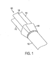
- FIG. 1 a partial view of an exemplary embodiment of a coal piping system in accordance with the invention is shown in Fig. 1 and is designated generally by reference character 100.
- FIGs. 2-5 Other embodiments of coal piping systems in accordance with the invention, or aspects thereof, are provided in Figs. 2-5 , as will be described.
- the systems and methods of the invention can be used to improve particle distribution downstream of piping splits, for example in coal piping systems and the like.
- Coal piping system 100 includes an upstream pipe 102 for conveying coal fines from an upstream source such as a pulverizer, in a flow of air to be burned in a downstream furnace or boiler.
- Flow splitter 104 connects to pipe 102 and includes internal components, which are described in detail below, for evenly distributing solid particles flowing in a fluid through system 100.
- the split in the flow from upstream pipe 102 is initiated by flow splitter 104, and the split is complete in downstream coal pipes 110. While only three pipes 110 are visible in the view of Fig. 1 , there are a total of four pipes 110, which lead to four respective coal nozzles, for example, where the coal is injected for combustion.
- flow splitter 104 is configured to be mounted between pipe 102 upstream and pipes 110 downstream.
- the circular flange 112 of pipe 102 can be bolted, e.g., buy bolts such as bolt 114, to circular flange 116 of flow splitter 104.
- the four pipes 110 are joined to flow splitter 104 by welding, or any other suitable joining technique.
- flow splitter 104 can be mounted between an existing upstream coal pipe and four downstream pipes, for example by fitting between existing pipe flanges, as a retrofit with little or no modification needed to the existing system.
- flow splitters such as flow splitter 104 can be mounted in newly constructed coal piping systems.
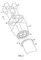
- a divider housing 124 which includes a circular inlet 126 mounted to upstream coal pipe 102 by flange 116 as described above.
- Inlet 126 is castellated with peripherally spaced teeth 132 that extend radially inward between peripherally spaced gaps 134 (in Fig. 3 , only some of the teeth 132 and gaps 134 are labeled with reference characters for sake of clarity).
- the outlet end 127 of divider housing 124 is generally rectangular.
- Divider housing 124 includes an outlet plate 108 that is mounted opposite inlet 126, perpendicular to longitudinal axis A, when assembled.
- Outlet plate 108 is generally rectangular, and the corners of the peripheries of outlet plate 108 and outlet end 127 have rounded corners.
- divider housing 124 generally define a shape that is a constant blend from a circular cross-section at circular inlet 126 to a square cross-section at rectangular outlet 127. While rectangular outlet 127 of divider housing 124 is shown and described as being square, those skilled in the art will readily appreciate that a rectangle of any other suitable proportions, or any other suitable shape in general, can be used for the outlet without departing from the spirit and scope of the invention.
- outlet plate 108 includes five circular apertures defined therethrough, including four outlet apertures 140 where the four downstream pipes 110 can be joined to flow splitter 104.
- the remaining aperture is central aperture 142, which is joined to the hollow outlet end of divider body 128 when assembled, so the center of flow splitter 104 is an open, hollow cone.
- Each of the rounded corners of outlet plate 108 is concentric with the respective adjacent outlet aperture 140.
- a divider body 128 is mounted in concentric, axial alignment within divider housing 124, and extends from the inlet end of divider housing 124 to outlet end 127 thereof.
- Divider body 128 is conical and diverges in a direction from the inlet end of divider housing 124 toward outlet end 127 thereof.
- divider vanes 130 are included within divider housing 124, each extending radially from divider body 128 in the center to the lengthwise outer wall 106 of divider housing 124.
- Divider housing 124, divider body 128, and divider vanes 130 are welded together, but could also be joined using any other suitable technique without departing from the spirit and scope of the invention.
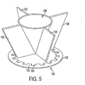
- Fig. 4 shows flow splitter 104 with outer wall 106 removed to show the arrangement of divider body 128 and divider vanes 130.
- the four divider vanes 130 are spaced apart circumferentially around a longitudinal axis of divider body 128 at 90° intervals. In the axial direction, the four divider vanes 130 extend from the inlet end to the outlet end of divider housing 124, and end proximate the outlet end of divider body 128.
- the outlet end of divider body 128 is hollow, with the downstream end thereof being open and joined to central aperture 142 when assembled, as described above.
- Divider vanes 130 are each aligned parallel to the longitudinal axis (labeled A in Fig. 3 ) running from the inlet end to the outlet end of divider body 128.
- the four divider vanes 130 are each aligned with a center of an edge of the rectangular outlet end 127 and outlet plate 108 of divider housing 124.
- the radially inner and outer edges of each divider vane 130 conform to the adjacent surface of divider body 128 and outer wall 106, respectively.
- the alignment of the divider vanes 128 and the teeth 132 and gaps 134 of inlet 126 shown in Figs. 2 and 4-5 is exemplary, as it is contemplated that any suitable alignment of these elements can be used without departing from the spirit and scope of the invention.
- Flow splitter 104 is a generally two-part construction, namely, the ring of toothed inlet 126, and the four-way distributor in the main portion of flow splitter 104 that includes four divider vanes 130.
- the overall shape and flow area of flow splitter 104 described above are configured to reduce or minimize the impact on pressure drop in coal piping systems utilizing flow splitter 104. It is contemplated that the pressure drop through flow splitter 104 can be less than about 3.2 inH 2 O A good way to quantify the pressure drop in this type of system is to measure pressure in planes located 3-5 diameters upstream and downstream of the device.
- flow area defined through flow splitter 104 need not necessarily be constant along a flow path from the inlet to the outlets, preferably the ratio of the inlet area to the outlet area (of all the inlets added together) is close to 1.0.
- Divider housing 124, divider body 128, and divider vanes 130 are configured and adapted to reduce non-uniformity in particle concentration from the inlet and to supply a substantially equal particle flow from outlet end 127 to each of the downstream pipes 110.
- flow splitter 104 is configured to break the coal rope and redistribute the coal particles between four downstream pipes, such as those in the directional flame burner coal nozzles described in U.S. Patent No. 5,623,884 , which is incorporated by reference herein in its entirety.
- Flow splitter 104 creates a more uniform coal distribution in a flow of coal passing therethrough, which results in improved controllable combustion performance.
- Flow splitter 104 is also configured and adapted to balance the flow of coal at the division point between the upstream coal pipe, e.g., pipe 102, and the four downstream pipes, e.g., pipes 110.
- flow splitter 104 improves particle distribution by both breaking up any coal rope to provide substantially equal amounts of coal to each downstream pipe 110, and also by distributing coal particles substantially uniformly within each downstream pipe 110. This is accomplished by the combination of the toothed ring of inlet 126 breaking any coal rope and by the flow splitter of vanes 130 further distributing and balancing the distribution of particles into the four downstream pipes 110. This is particularly advantageous when the four downstream pipes 110 are part of directional flame burner coal nozzles.
- flow splitter 104 balances the flow in piping system 100, the more even distribution of coal particles and air in each downstream pipe 110 produces a more uniform, balanced flow to the burners, nozzles, or the like, downstream thereof.
- the specific shape of flow splitter 104 creates regions of cross mixing using a combination of sloped (e.g., the surface of divider body 128), segmented (e.g., the toothed portion of inlet 126), and solid (e.g. the surfaces of vanes 130) areas around the circumference of the device. Precise placement of flow splitter 104 is based on coal pipe orientation and is important for optimum fuel balancing.
- the placement shown and described herein is exemplary, and those skilled in the art will readily appreciate that any other suitable positioning can be used for a given application without departing from the spirit and scope of the invention.
Landscapes
- Engineering & Computer Science (AREA)
- Chemical & Material Sciences (AREA)
- Combustion & Propulsion (AREA)
- Mechanical Engineering (AREA)
- General Engineering & Computer Science (AREA)
- Feeding, Discharge, Calcimining, Fusing, And Gas-Generation Devices (AREA)
- Air Transport Of Granular Materials (AREA)
- Devices And Processes Conducted In The Presence Of Fluids And Solid Particles (AREA)
- Fluidized-Bed Combustion And Resonant Combustion (AREA)
Applications Claiming Priority (1)
| Application Number | Priority Date | Filing Date | Title |
|---|---|---|---|
| US13/048,921 US8403602B2 (en) | 2011-03-16 | 2011-03-16 | Coal flow splitters and distributor devices |
Publications (3)
| Publication Number | Publication Date |
|---|---|
| EP2500647A2 true EP2500647A2 (de) | 2012-09-19 |
| EP2500647A3 EP2500647A3 (de) | 2014-01-15 |
| EP2500647B1 EP2500647B1 (de) | 2015-06-03 |
Family
ID=45656232
Family Applications (1)
| Application Number | Title | Priority Date | Filing Date |
|---|---|---|---|
| EP12156255.7A Not-in-force EP2500647B1 (de) | 2011-03-16 | 2012-02-20 | Kohleflussteiler und Verteilervorrichtungen |
Country Status (3)
| Country | Link |
|---|---|
| US (1) | US8403602B2 (de) |
| EP (1) | EP2500647B1 (de) |
| JP (1) | JP6016395B2 (de) |
Cited By (4)
| Publication number | Priority date | Publication date | Assignee | Title |
|---|---|---|---|---|
| CN105485709A (zh) * | 2016-01-05 | 2016-04-13 | 上海发电设备成套设计研究院 | 一种可调节式煤粉分配器 |
| WO2017148954A1 (en) * | 2016-02-29 | 2017-09-08 | General Electric Technology Gmbh | System, method and apparatus for controlling the flow distribution of solid particles |
| CN107906556A (zh) * | 2017-11-07 | 2018-04-13 | 南京科远自动化集团股份有限公司 | 一种粉煤分配器均衡控制方法及均衡控制装置 |
| CN109681899A (zh) * | 2018-12-26 | 2019-04-26 | 上海发电设备成套设计研究院有限责任公司 | 一种电站锅炉可调节煤粉均分器及其使用方法 |
Families Citing this family (13)
| Publication number | Priority date | Publication date | Assignee | Title |
|---|---|---|---|---|
| CN101846315B (zh) * | 2009-03-24 | 2012-07-04 | 烟台龙源电力技术股份有限公司 | 煤粉浓缩装置和包含该煤粉浓缩装置的内燃式煤粉燃烧器 |
| CA2830535C (en) | 2011-03-24 | 2018-12-04 | Babcock Power Services, Inc. | Coal flow distribution controllers for coal pulverizers |
| WO2013106727A1 (en) * | 2012-01-13 | 2013-07-18 | Babcock Power Services, Inc. | Adjustable division plate for classifier coal flow control |
| US10306825B2 (en) | 2014-11-04 | 2019-06-04 | Cnh Industrial Canada, Ltd. | Air distribution system for a pneumatic conveying system |
| CN105546569B (zh) * | 2016-01-05 | 2017-11-21 | 上海发电设备成套设计研究院 | 一种可调节风速及煤粉浓度的煤粉分配器 |
| US9902571B2 (en) | 2016-02-29 | 2018-02-27 | Cnh Industrial Canada, Ltd. | Air distribution system for a pneumatic conveying system |
| US10363564B2 (en) * | 2016-02-29 | 2019-07-30 | General Electric Technology Gmbh | System, method and apparatus for controlling the flow distribution of solid particles |
| ITUA20163690A1 (it) * | 2016-05-23 | 2017-11-23 | I M A Industria Macch Automatiche S P A In Sigla Ima S P A | Apparato di dosaggio per prodotti in polvere. |
| US10143129B2 (en) * | 2017-02-27 | 2018-12-04 | Cnh Industrial Canada, Ltd. | Flow splitter for distributing agricultural products and related system |
| US10427113B2 (en) | 2017-07-18 | 2019-10-01 | Cnh Industrial Canada, Ltd. | Horizontal product distribution system using static baffles in a distributor |
| US10743462B2 (en) * | 2019-01-11 | 2020-08-18 | Cnh Industrial America Llc | Flow splitter for distributing agricultural products and related system |
| US11547038B2 (en) * | 2019-10-31 | 2023-01-10 | Deere & Company | Plenum for air seeding machine and method of use |
| US11350561B2 (en) * | 2019-11-22 | 2022-06-07 | Cnh Industrial Canada, Ltd. | Balanced fan plenum for distributing particulate material |
Citations (1)
| Publication number | Priority date | Publication date | Assignee | Title |
|---|---|---|---|---|
| US5623884A (en) | 1995-12-05 | 1997-04-29 | Db Riley, Inc. | Tilting coal nozzle burner apparatus |
Family Cites Families (34)
| Publication number | Priority date | Publication date | Assignee | Title |
|---|---|---|---|---|
| US1871853A (en) * | 1927-08-09 | 1932-08-16 | Joseph E Kennedy | Pneumatic transporting and distributing of pulverized material |
| US2975001A (en) | 1957-11-26 | 1961-03-14 | Int Combustion Holdings Ltd | Apparatus for the distribution of pulverised fuels |
| US3265442A (en) * | 1965-01-18 | 1966-08-09 | Foster Wheeler Corp | Distributor for plverized material |
| US4094492A (en) | 1977-01-18 | 1978-06-13 | The United States Of America As Represented By The United States Department Of Energy | Variable orifice using an iris shutter |
| US4191500A (en) * | 1977-07-27 | 1980-03-04 | Rockwell International Corporation | Dense-phase feeder method |
| CA1094612A (en) * | 1977-07-27 | 1981-01-27 | Carl L. Oberg | Dense-phase feeder method |
| US4356975A (en) | 1980-03-07 | 1982-11-02 | Combustion Engineering, Inc. | Nozzle tip for pulverized coal burner |
| US4412496A (en) | 1982-04-27 | 1983-11-01 | Foster Wheeler Energy Corp. | Combustion system and method for a coal-fired furnace utilizing a low load coal burner |
| US4478157A (en) | 1982-11-18 | 1984-10-23 | Combustion Engineering, Inc. | Mill recirculation system |
| US4459922A (en) | 1983-01-24 | 1984-07-17 | Combustion Engineering, Inc. | Externally adjustable pipe orifice assembly |
| US4634054A (en) | 1983-04-22 | 1987-01-06 | Combustion Engineering, Inc. | Split nozzle tip for pulverized coal burner |
| US4562968A (en) * | 1984-03-19 | 1986-01-07 | Dry Sprayer, Inc. | Pneumatic spreader |
| US4570549A (en) | 1984-05-17 | 1986-02-18 | Trozzi Norman K | Splitter for use with a coal-fired furnace utilizing a low load burner |
| SE457528B (sv) * | 1984-12-04 | 1989-01-09 | Flaekt Ab | Foer soenderdelade fasta partiklar avsedd partikeltransporterande anordning |
| US4779546A (en) | 1986-04-11 | 1988-10-25 | Combustion Engineering, Inc. | Fuel line orifice |
| US5215259A (en) | 1991-08-13 | 1993-06-01 | Sure Alloy Steel Corporation | Replaceable insert burner nozzle |
| DE19520845C2 (de) * | 1995-06-08 | 1997-06-26 | Omya Gmbh | Zentrifugalkraftsichter |
| US5593131A (en) | 1995-11-13 | 1997-01-14 | Db Riley, Inc. | Variable orifice plate for coal pipes |
| US5934205A (en) | 1996-12-23 | 1999-08-10 | Combustion Engineering, Inc. | Y-shaped distributor with liner assembly for distribution of pulverized coal and air mixture |
| US6055914A (en) | 1997-12-09 | 2000-05-02 | Sure Alloy Steel Corporation | Pre-riffle box mixing device for coal-fired power plant |
| GB9802527D0 (en) * | 1998-02-06 | 1998-04-01 | Flexi Coil Ltd | Delivery of seeds by air conveyor |
| US5975141A (en) | 1998-03-09 | 1999-11-02 | The Detroit Edison Company | On-line variable orifice |
| US5979343A (en) * | 1998-07-16 | 1999-11-09 | Deere & Company | Plenum damper and baffle plate arrangement for pneumatic distribution system |
| US6588598B2 (en) | 1999-11-15 | 2003-07-08 | Rickey E. Wark | Multi-outlet diffuser system for classifier cones |
| US6789488B2 (en) | 2000-04-24 | 2004-09-14 | Edward Kenneth Levy | Adjustable flow control elements for balancing pulverized coal flow at coal pipe splitter junctions |
| US7013815B2 (en) | 2000-04-24 | 2006-03-21 | Ferruhyie Yilmaz, legal representative | Adjustable air foils for balancing pulverized coal flow at a coal pipe splitter junction |
| US6494151B1 (en) * | 2000-04-25 | 2002-12-17 | Sure Alloy Steel Corporation | Exhauster diffuser discharge valve |
| US6811358B2 (en) | 2002-02-27 | 2004-11-02 | Alstom Technology Ltd | Adjustable flow vectoring splitter |
| US6899041B2 (en) * | 2003-04-17 | 2005-05-31 | Rickey E. Wark | Multi-spin mixer for particulate coal supply conduit |
| US7017501B2 (en) | 2004-01-22 | 2006-03-28 | Alstom Technology Ltd | Riffle distributor assembly for a fossil fuel fired combustion arrangement |
| DE202007002968U1 (de) * | 2007-02-27 | 2007-08-16 | Elsen, Guido Gerhard Ulf | Vorrichtung zum Steuern oder Regeln der Verteilung von staub- oder granulatförmigen Partikeln in einem oder mehreren Trägergasströmen |
| US8082860B2 (en) * | 2008-04-30 | 2011-12-27 | Babcock Power Services Inc. | Anti-roping device for pulverized coal burners |
| US9151434B2 (en) | 2008-12-18 | 2015-10-06 | Alstom Technology Ltd | Coal rope distributor with replaceable wear components |
| US9797599B2 (en) * | 2011-01-20 | 2017-10-24 | Babcock Power Services, Inc. | Coal flow balancing devices |
-
2011
- 2011-03-16 US US13/048,921 patent/US8403602B2/en not_active Expired - Fee Related
-
2012
- 2012-02-20 EP EP12156255.7A patent/EP2500647B1/de not_active Not-in-force
- 2012-03-16 JP JP2012060691A patent/JP6016395B2/ja not_active Expired - Fee Related
Patent Citations (1)
| Publication number | Priority date | Publication date | Assignee | Title |
|---|---|---|---|---|
| US5623884A (en) | 1995-12-05 | 1997-04-29 | Db Riley, Inc. | Tilting coal nozzle burner apparatus |
Cited By (6)
| Publication number | Priority date | Publication date | Assignee | Title |
|---|---|---|---|---|
| CN105485709A (zh) * | 2016-01-05 | 2016-04-13 | 上海发电设备成套设计研究院 | 一种可调节式煤粉分配器 |
| WO2017148954A1 (en) * | 2016-02-29 | 2017-09-08 | General Electric Technology Gmbh | System, method and apparatus for controlling the flow distribution of solid particles |
| US10493463B2 (en) | 2016-02-29 | 2019-12-03 | General Electric Technology Gmbh | System, method and apparatus for controlling the flow distribution of solid particles |
| CN107906556A (zh) * | 2017-11-07 | 2018-04-13 | 南京科远自动化集团股份有限公司 | 一种粉煤分配器均衡控制方法及均衡控制装置 |
| CN107906556B (zh) * | 2017-11-07 | 2019-04-05 | 南京科远自动化集团股份有限公司 | 一种粉煤分配器均衡控制方法及均衡控制装置 |
| CN109681899A (zh) * | 2018-12-26 | 2019-04-26 | 上海发电设备成套设计研究院有限责任公司 | 一种电站锅炉可调节煤粉均分器及其使用方法 |
Also Published As
| Publication number | Publication date |
|---|---|
| JP6016395B2 (ja) | 2016-10-26 |
| JP2012192404A (ja) | 2012-10-11 |
| US20120237304A1 (en) | 2012-09-20 |
| EP2500647A3 (de) | 2014-01-15 |
| US8403602B2 (en) | 2013-03-26 |
| EP2500647B1 (de) | 2015-06-03 |
| CN102705856A (zh) | 2012-10-03 |
Similar Documents
| Publication | Publication Date | Title |
|---|---|---|
| US8403602B2 (en) | Coal flow splitters and distributor devices | |
| US9797599B2 (en) | Coal flow balancing devices | |
| CN104246371B (zh) | 涡轮机燃烧器组装件 | |
| US10502426B2 (en) | Dual fuel injectors and methods of use in gas turbine combustor | |
| US9534781B2 (en) | System and method having multi-tube fuel nozzle with differential flow | |
| CN103471136B (zh) | 具有燃料预混器的燃烧器组件 | |
| CA2733238C (en) | Deflector device for coal piping systems | |
| US8082860B2 (en) | Anti-roping device for pulverized coal burners | |
| US6899041B2 (en) | Multi-spin mixer for particulate coal supply conduit | |
| TWI540288B (zh) | 用於分配石化燃料之總成 | |
| RU2552888C2 (ru) | Башенный распределитель на электростанции, работающей на угле (варианты) | |
| CN102705856B (zh) | 煤分流器及分布器装置 | |
| US9657944B2 (en) | Assembly for fossil fuel distribution |
Legal Events
| Date | Code | Title | Description |
|---|---|---|---|
| PUAI | Public reference made under article 153(3) epc to a published international application that has entered the european phase |
Free format text: ORIGINAL CODE: 0009012 |
|
| AK | Designated contracting states |
Kind code of ref document: A2 Designated state(s): AL AT BE BG CH CY CZ DE DK EE ES FI FR GB GR HR HU IE IS IT LI LT LU LV MC MK MT NL NO PL PT RO RS SE SI SK SM TR |
|
| AX | Request for extension of the european patent |
Extension state: BA ME |
|
| PUAL | Search report despatched |
Free format text: ORIGINAL CODE: 0009013 |
|
| AK | Designated contracting states |
Kind code of ref document: A3 Designated state(s): AL AT BE BG CH CY CZ DE DK EE ES FI FR GB GR HR HU IE IS IT LI LT LU LV MC MK MT NL NO PL PT RO RS SE SI SK SM TR |
|
| AX | Request for extension of the european patent |
Extension state: BA ME |
|
| RIC1 | Information provided on ipc code assigned before grant |
Ipc: F23K 3/00 20060101AFI20131211BHEP |
|
| 17P | Request for examination filed |
Effective date: 20140715 |
|
| RBV | Designated contracting states (corrected) |
Designated state(s): AL AT BE BG CH CY CZ DE DK EE ES FI FR GB GR HR HU IE IS IT LI LT LU LV MC MK MT NL NO PL PT RO RS SE SI SK SM TR |
|
| GRAP | Despatch of communication of intention to grant a patent |
Free format text: ORIGINAL CODE: EPIDOSNIGR1 |
|
| INTG | Intention to grant announced |
Effective date: 20141217 |
|
| GRAS | Grant fee paid |
Free format text: ORIGINAL CODE: EPIDOSNIGR3 |
|
| GRAA | (expected) grant |
Free format text: ORIGINAL CODE: 0009210 |
|
| AK | Designated contracting states |
Kind code of ref document: B1 Designated state(s): AL AT BE BG CH CY CZ DE DK EE ES FI FR GB GR HR HU IE IS IT LI LT LU LV MC MK MT NL NO PL PT RO RS SE SI SK SM TR |
|
| REG | Reference to a national code |
Ref country code: GB Ref legal event code: FG4D |
|
| REG | Reference to a national code |
Ref country code: CH Ref legal event code: EP |
|
| REG | Reference to a national code |
Ref country code: AT Ref legal event code: REF Ref document number: 730108 Country of ref document: AT Kind code of ref document: T Effective date: 20150715 Ref country code: IE Ref legal event code: FG4D |
|
| REG | Reference to a national code |
Ref country code: DE Ref legal event code: R096 Ref document number: 602012007668 Country of ref document: DE |
|
| REG | Reference to a national code |
Ref country code: AT Ref legal event code: MK05 Ref document number: 730108 Country of ref document: AT Kind code of ref document: T Effective date: 20150603 |
|
| PG25 | Lapsed in a contracting state [announced via postgrant information from national office to epo] |
Ref country code: HR Free format text: LAPSE BECAUSE OF FAILURE TO SUBMIT A TRANSLATION OF THE DESCRIPTION OR TO PAY THE FEE WITHIN THE PRESCRIBED TIME-LIMIT Effective date: 20150603 Ref country code: ES Free format text: LAPSE BECAUSE OF FAILURE TO SUBMIT A TRANSLATION OF THE DESCRIPTION OR TO PAY THE FEE WITHIN THE PRESCRIBED TIME-LIMIT Effective date: 20150603 Ref country code: LT Free format text: LAPSE BECAUSE OF FAILURE TO SUBMIT A TRANSLATION OF THE DESCRIPTION OR TO PAY THE FEE WITHIN THE PRESCRIBED TIME-LIMIT Effective date: 20150603 Ref country code: FI Free format text: LAPSE BECAUSE OF FAILURE TO SUBMIT A TRANSLATION OF THE DESCRIPTION OR TO PAY THE FEE WITHIN THE PRESCRIBED TIME-LIMIT Effective date: 20150603 Ref country code: NO Free format text: LAPSE BECAUSE OF FAILURE TO SUBMIT A TRANSLATION OF THE DESCRIPTION OR TO PAY THE FEE WITHIN THE PRESCRIBED TIME-LIMIT Effective date: 20150903 |
|
| REG | Reference to a national code |
Ref country code: NL Ref legal event code: MP Effective date: 20150603 |
|
| REG | Reference to a national code |
Ref country code: LT Ref legal event code: MG4D |
|
| PG25 | Lapsed in a contracting state [announced via postgrant information from national office to epo] |
Ref country code: BG Free format text: LAPSE BECAUSE OF FAILURE TO SUBMIT A TRANSLATION OF THE DESCRIPTION OR TO PAY THE FEE WITHIN THE PRESCRIBED TIME-LIMIT Effective date: 20150903 Ref country code: RS Free format text: LAPSE BECAUSE OF FAILURE TO SUBMIT A TRANSLATION OF THE DESCRIPTION OR TO PAY THE FEE WITHIN THE PRESCRIBED TIME-LIMIT Effective date: 20150603 Ref country code: GR Free format text: LAPSE BECAUSE OF FAILURE TO SUBMIT A TRANSLATION OF THE DESCRIPTION OR TO PAY THE FEE WITHIN THE PRESCRIBED TIME-LIMIT Effective date: 20150904 Ref country code: AT Free format text: LAPSE BECAUSE OF FAILURE TO SUBMIT A TRANSLATION OF THE DESCRIPTION OR TO PAY THE FEE WITHIN THE PRESCRIBED TIME-LIMIT Effective date: 20150603 Ref country code: LV Free format text: LAPSE BECAUSE OF FAILURE TO SUBMIT A TRANSLATION OF THE DESCRIPTION OR TO PAY THE FEE WITHIN THE PRESCRIBED TIME-LIMIT Effective date: 20150603 |
|
| PG25 | Lapsed in a contracting state [announced via postgrant information from national office to epo] |
Ref country code: EE Free format text: LAPSE BECAUSE OF FAILURE TO SUBMIT A TRANSLATION OF THE DESCRIPTION OR TO PAY THE FEE WITHIN THE PRESCRIBED TIME-LIMIT Effective date: 20150603 |
|
| PG25 | Lapsed in a contracting state [announced via postgrant information from national office to epo] |
Ref country code: SK Free format text: LAPSE BECAUSE OF FAILURE TO SUBMIT A TRANSLATION OF THE DESCRIPTION OR TO PAY THE FEE WITHIN THE PRESCRIBED TIME-LIMIT Effective date: 20150603 Ref country code: PT Free format text: LAPSE BECAUSE OF FAILURE TO SUBMIT A TRANSLATION OF THE DESCRIPTION OR TO PAY THE FEE WITHIN THE PRESCRIBED TIME-LIMIT Effective date: 20151006 Ref country code: IS Free format text: LAPSE BECAUSE OF FAILURE TO SUBMIT A TRANSLATION OF THE DESCRIPTION OR TO PAY THE FEE WITHIN THE PRESCRIBED TIME-LIMIT Effective date: 20151003 Ref country code: RO Free format text: LAPSE BECAUSE OF NON-PAYMENT OF DUE FEES Effective date: 20150603 Ref country code: PL Free format text: LAPSE BECAUSE OF FAILURE TO SUBMIT A TRANSLATION OF THE DESCRIPTION OR TO PAY THE FEE WITHIN THE PRESCRIBED TIME-LIMIT Effective date: 20150603 Ref country code: CZ Free format text: LAPSE BECAUSE OF FAILURE TO SUBMIT A TRANSLATION OF THE DESCRIPTION OR TO PAY THE FEE WITHIN THE PRESCRIBED TIME-LIMIT Effective date: 20150603 |
|
| REG | Reference to a national code |
Ref country code: DE Ref legal event code: R097 Ref document number: 602012007668 Country of ref document: DE |
|
| PLBE | No opposition filed within time limit |
Free format text: ORIGINAL CODE: 0009261 |
|
| STAA | Information on the status of an ep patent application or granted ep patent |
Free format text: STATUS: NO OPPOSITION FILED WITHIN TIME LIMIT |
|
| PG25 | Lapsed in a contracting state [announced via postgrant information from national office to epo] |
Ref country code: IT Free format text: LAPSE BECAUSE OF FAILURE TO SUBMIT A TRANSLATION OF THE DESCRIPTION OR TO PAY THE FEE WITHIN THE PRESCRIBED TIME-LIMIT Effective date: 20150603 Ref country code: DK Free format text: LAPSE BECAUSE OF FAILURE TO SUBMIT A TRANSLATION OF THE DESCRIPTION OR TO PAY THE FEE WITHIN THE PRESCRIBED TIME-LIMIT Effective date: 20150603 |
|
| 26N | No opposition filed |
Effective date: 20160304 |
|
| PG25 | Lapsed in a contracting state [announced via postgrant information from national office to epo] |
Ref country code: SI Free format text: LAPSE BECAUSE OF FAILURE TO SUBMIT A TRANSLATION OF THE DESCRIPTION OR TO PAY THE FEE WITHIN THE PRESCRIBED TIME-LIMIT Effective date: 20150603 Ref country code: BE Free format text: LAPSE BECAUSE OF NON-PAYMENT OF DUE FEES Effective date: 20160229 |
|
| REG | Reference to a national code |
Ref country code: DE Ref legal event code: R119 Ref document number: 602012007668 Country of ref document: DE |
|
| PG25 | Lapsed in a contracting state [announced via postgrant information from national office to epo] |
Ref country code: LU Free format text: LAPSE BECAUSE OF FAILURE TO SUBMIT A TRANSLATION OF THE DESCRIPTION OR TO PAY THE FEE WITHIN THE PRESCRIBED TIME-LIMIT Effective date: 20160220 Ref country code: MC Free format text: LAPSE BECAUSE OF FAILURE TO SUBMIT A TRANSLATION OF THE DESCRIPTION OR TO PAY THE FEE WITHIN THE PRESCRIBED TIME-LIMIT Effective date: 20150603 |
|
| REG | Reference to a national code |
Ref country code: CH Ref legal event code: PL |
|
| GBPC | Gb: european patent ceased through non-payment of renewal fee |
Effective date: 20160220 |
|
| PG25 | Lapsed in a contracting state [announced via postgrant information from national office to epo] |
Ref country code: LI Free format text: LAPSE BECAUSE OF NON-PAYMENT OF DUE FEES Effective date: 20160229 Ref country code: CH Free format text: LAPSE BECAUSE OF NON-PAYMENT OF DUE FEES Effective date: 20160229 |
|
| REG | Reference to a national code |
Ref country code: FR Ref legal event code: ST Effective date: 20161028 |
|
| REG | Reference to a national code |
Ref country code: IE Ref legal event code: MM4A |
|
| PG25 | Lapsed in a contracting state [announced via postgrant information from national office to epo] |
Ref country code: BE Free format text: LAPSE BECAUSE OF FAILURE TO SUBMIT A TRANSLATION OF THE DESCRIPTION OR TO PAY THE FEE WITHIN THE PRESCRIBED TIME-LIMIT Effective date: 20150603 |
|
| PG25 | Lapsed in a contracting state [announced via postgrant information from national office to epo] |
Ref country code: FR Free format text: LAPSE BECAUSE OF NON-PAYMENT OF DUE FEES Effective date: 20160229 Ref country code: DE Free format text: LAPSE BECAUSE OF NON-PAYMENT OF DUE FEES Effective date: 20160901 Ref country code: GB Free format text: LAPSE BECAUSE OF NON-PAYMENT OF DUE FEES Effective date: 20160220 Ref country code: IE Free format text: LAPSE BECAUSE OF NON-PAYMENT OF DUE FEES Effective date: 20160220 |
|
| PG25 | Lapsed in a contracting state [announced via postgrant information from national office to epo] |
Ref country code: SE Free format text: LAPSE BECAUSE OF FAILURE TO SUBMIT A TRANSLATION OF THE DESCRIPTION OR TO PAY THE FEE WITHIN THE PRESCRIBED TIME-LIMIT Effective date: 20150603 Ref country code: NL Free format text: LAPSE BECAUSE OF FAILURE TO SUBMIT A TRANSLATION OF THE DESCRIPTION OR TO PAY THE FEE WITHIN THE PRESCRIBED TIME-LIMIT Effective date: 20150603 |
|
| PG25 | Lapsed in a contracting state [announced via postgrant information from national office to epo] |
Ref country code: MT Free format text: LAPSE BECAUSE OF FAILURE TO SUBMIT A TRANSLATION OF THE DESCRIPTION OR TO PAY THE FEE WITHIN THE PRESCRIBED TIME-LIMIT Effective date: 20150603 |
|
| PG25 | Lapsed in a contracting state [announced via postgrant information from national office to epo] |
Ref country code: CY Free format text: LAPSE BECAUSE OF FAILURE TO SUBMIT A TRANSLATION OF THE DESCRIPTION OR TO PAY THE FEE WITHIN THE PRESCRIBED TIME-LIMIT Effective date: 20150603 Ref country code: SM Free format text: LAPSE BECAUSE OF FAILURE TO SUBMIT A TRANSLATION OF THE DESCRIPTION OR TO PAY THE FEE WITHIN THE PRESCRIBED TIME-LIMIT Effective date: 20150603 Ref country code: HU Free format text: LAPSE BECAUSE OF FAILURE TO SUBMIT A TRANSLATION OF THE DESCRIPTION OR TO PAY THE FEE WITHIN THE PRESCRIBED TIME-LIMIT; INVALID AB INITIO Effective date: 20120220 |
|
| PG25 | Lapsed in a contracting state [announced via postgrant information from national office to epo] |
Ref country code: MT Free format text: LAPSE BECAUSE OF FAILURE TO SUBMIT A TRANSLATION OF THE DESCRIPTION OR TO PAY THE FEE WITHIN THE PRESCRIBED TIME-LIMIT Effective date: 20160229 Ref country code: MK Free format text: LAPSE BECAUSE OF FAILURE TO SUBMIT A TRANSLATION OF THE DESCRIPTION OR TO PAY THE FEE WITHIN THE PRESCRIBED TIME-LIMIT Effective date: 20150603 Ref country code: TR Free format text: LAPSE BECAUSE OF FAILURE TO SUBMIT A TRANSLATION OF THE DESCRIPTION OR TO PAY THE FEE WITHIN THE PRESCRIBED TIME-LIMIT Effective date: 20150603 |
|
| PG25 | Lapsed in a contracting state [announced via postgrant information from national office to epo] |
Ref country code: AL Free format text: LAPSE BECAUSE OF FAILURE TO SUBMIT A TRANSLATION OF THE DESCRIPTION OR TO PAY THE FEE WITHIN THE PRESCRIBED TIME-LIMIT Effective date: 20150603 |