EP2500652A2 - Dispositif de chauffage destiné à la combustion de biomasse - Google Patents
Dispositif de chauffage destiné à la combustion de biomasse Download PDFInfo
- Publication number
- EP2500652A2 EP2500652A2 EP12159253A EP12159253A EP2500652A2 EP 2500652 A2 EP2500652 A2 EP 2500652A2 EP 12159253 A EP12159253 A EP 12159253A EP 12159253 A EP12159253 A EP 12159253A EP 2500652 A2 EP2500652 A2 EP 2500652A2
- Authority
- EP
- European Patent Office
- Prior art keywords
- flue gas
- combustion chamber
- supply
- heating device
- fuel
- Prior art date
- Legal status (The legal status is an assumption and is not a legal conclusion. Google has not performed a legal analysis and makes no representation as to the accuracy of the status listed.)
- Granted
Links
Images

Classifications
-
- F—MECHANICAL ENGINEERING; LIGHTING; HEATING; WEAPONS; BLASTING
- F24—HEATING; RANGES; VENTILATING
- F24B—DOMESTIC STOVES OR RANGES FOR SOLID FUELS; IMPLEMENTS FOR USE IN CONNECTION WITH STOVES OR RANGES
- F24B5/00—Combustion-air or flue-gas circulation in or around stoves or ranges
- F24B5/02—Combustion-air or flue-gas circulation in or around stoves or ranges in or around stoves
-
- F—MECHANICAL ENGINEERING; LIGHTING; HEATING; WEAPONS; BLASTING
- F23—COMBUSTION APPARATUS; COMBUSTION PROCESSES
- F23B—METHODS OR APPARATUS FOR COMBUSTION USING ONLY SOLID FUEL
- F23B80/00—Combustion apparatus characterised by means creating a distinct flow path for flue gases or for non-combusted gases given off by the fuel
- F23B80/04—Combustion apparatus characterised by means creating a distinct flow path for flue gases or for non-combusted gases given off by the fuel by means for guiding the flow of flue gases, e.g. baffles
-
- F—MECHANICAL ENGINEERING; LIGHTING; HEATING; WEAPONS; BLASTING
- F23—COMBUSTION APPARATUS; COMBUSTION PROCESSES
- F23N—REGULATING OR CONTROLLING COMBUSTION
- F23N5/00—Systems for controlling combustion
- F23N5/24—Preventing development of abnormal or undesired conditions, i.e. safety arrangements
-
- F—MECHANICAL ENGINEERING; LIGHTING; HEATING; WEAPONS; BLASTING
- F23—COMBUSTION APPARATUS; COMBUSTION PROCESSES
- F23N—REGULATING OR CONTROLLING COMBUSTION
- F23N2231/00—Fail safe
- F23N2231/04—Fail safe for electrical power failures
-
- F—MECHANICAL ENGINEERING; LIGHTING; HEATING; WEAPONS; BLASTING
- F23—COMBUSTION APPARATUS; COMBUSTION PROCESSES
- F23N—REGULATING OR CONTROLLING COMBUSTION
- F23N2239/00—Fuels
- F23N2239/02—Solid fuels
Definitions
- the invention relates to a heating device with a combustion chamber for combustion of biomass-based fuel, as specified in claim 1.
- a generic heater for burning biomass known.
- the provided for combustion in this heater biomass is defined by pellets, which by means of an electric motor driven, obliquely upwardly conveying conveyor and a downstream chute or gravity chute, starting from the bottom of a reservoir for pellets from above into a burner chamber located in the combustion chamber burner shell be promoted for burning the pellets.
- a flue gas blower is provided which directs the flue gases via a vertical flue gas channel in the direction of a flue gas outlet opening positioned in the lower end section of the rear side of the heating device.
- the present invention has for its object to provide a heating device, which on the one hand offers increased ease of use and on the other hand, the achievement of the highest possible thermal efficiency possible.
- a heating device for direct installation in residential areas to create which allows not only increased ease of use and ease of use and the highest possible efficiency in terms of the heat energy provided, also a particularly safe or problem-free operation possible.
- An advantage of the measures according to the invention is a high thermal efficiency in relation to the calorific value of the supplied fuel material and the heat source provided therefrom and / or generated by the heat exchanger implemented in or on the heating device Heat energy for heating the ambient air is achieved.
- thermal efficiency of the heater can be positively influenced, inter alia, by the electric flue gas blower.
- the flue gas blower can be controlled or regulated by simple control measures that the heat energy contained in the flue gas is transferred to the highest possible percentage of the surfaces of the heat exchanger, so that it can contribute to the most efficient heating of the ambient air to the heater.
- a significant advantage of the inventive measures is that in addition to the optimization of the efficiency of the heater and the combustion process can be favored by the flue gas fan can provide for optimized supply of combustion air into the combustion chamber.
- an optimal combustion process can be achieved by means of simple control-related processes, in particular via defined on / off commands and / or via speed control of the flue gas blower, by means of favorable negative pressure values in the combustion chamber and thus by ideal quantities or volumes of supplied combustion air.
- by optimizing the amount of combustion air supplied and sucked in via the flue gas blower a favorable operating point with regard to the most economical or efficient and at the same time low-emission combustion of the fuel material can be ensured.
- An essential advantage of the measures according to the invention is that a heating device designed in accordance with the claim has a high degree of operational reliability or automatically prevents or automatically precludes the emergence of critical operating states. In particular, it is ensured that in case of sudden or unforeseen failure of the function of the flue gas blower, especially in the absence of suction or pressure effect of the flue gas fan, a proper burn of still existing in the combustion chamber of the heater or already existing, and located in the fire phase fuel ensures is.
- the actuator according to the invention which is automatically transferred in case of failure or interruption of the electrical operating or supply energy for the heater in a working or open position, that a sufficient discharge of resulting flue gases or a sufficient supply of combustion air is guaranteed ,
- by shortening or bypassing the flues of the heat exchanger ensures that even without fan support a problem-free burning of the fuel or a sufficient Supply of oxygen takes place.
- automatically or automatically switched to a special operating state of the heater according to the invention in case of failure or partial failure of the electrical operating or supply energy, in which even without the support of the flue gas fan sufficient or proper removal of the flue gases and / or a sufficient supply of combustion air guaranteed remains.
- the heat exchanger has long flue gas ducts in order to achieve high efficiency, without the measures according to the invention in the event of a power failure or a technical defect, a bad combustion process or a gradual defrosting and increased flue gas concentration in the combustion chamber would occur.
- poor combustion processes may result in increased concentrations of combustible gases, which can lead to critical deflagration.
- increased flue gas concentrations in the combustion chamber in case of improper or hasty actions by the operator would quickly lead to contamination or critical flue gas developments outside of the combustion chamber of the heater.
- relatively critical states are reliably and automatically excluded by the inventive measures, without the need for elaborate, electronic monitoring systems are required.
- the measures according to claim 2 since it is created in the absence of support by the flue gas directly a bypass or fluidic separation of the heat exchanger for the flue gases and natural or thermal convection removal of flue gases from the combustion chamber and a sufficient supply combustion air is ensured in the combustion chamber.
- a sufficient negative pressure or a so-called train in the combustion chamber is maintained by these measures, so that a proper or uncritical burn-off of the remaining in the combustion chamber, already in the combustion process fuel is ensured.
- the heat exchanger or its flue gas ducts are quasi short-circuited or bypassed in a simple manner or bridged by the measures according to claim 2.
- the actuator since thereby the actuator only then, and only then can be transferred back into the closed position as soon as the electrical operating or supply energy is present or is available again.
- This ensures that a flue gas duct can only take place via the heat exchanger when the flue gas blower or the control device can again fulfill or assume the planned function.
- this ruled out in a simple manner that after a transfer of the actuator in the open position - in particular due to a failure of the electrical operating or supply energy or due to a technical conditional failure of the flue gas fan - the user by carelessness or ignorance, the actuator so switches, that the flue gas is forced to tread over the relatively long, increased flow resistance having flow path through the heat exchanger.
- the actuator can only be transferred to the closed position, if the conditions for an electrically assisted or automation-supported operation of the heater are secured.
- the actuator is designed as a pivotable damper, which offers a high functional and operational reliability.
- this ensures a high level of functional reliability for the corresponding adjusting element even in the case of contaminants, as naturally occur in the flue gas tract of the heating device.
- a pivot bearing in comparison to a linear guide is comparatively more robust with respect to soot or particle accumulation, after pivot bearings can be constructed substantially free of jamming, as translational guides or linearly adjustable slide elements.
- the measures or conditions according to claim 6 ensures that when the bypass opening is active or open, a withdrawal of the flue gases via the bypass opening automatically occurs and there is a reliable discharge of the exhaust gases from the combustion chamber.
- the measures according to claim 7 it is ensured that in case of failure of the flue gas fan, especially when interrupting the electrical power supply for the heater or to the heater, constructed by chimney effect removal of flue gases from the combustion chamber is guaranteed and the heat exchanger is fluidically quasi shorted.
- a burn-back in the supply channel for fuel or in the reservoir can be reliably excluded.
- a burn-back in the supply channel for fuel or in the reservoir can be reliably excluded.
- in case of failure of the conveyor or in constipation problems in the supply channel for example with respect to a screw conveyor reliably prevents a befindliches in the feed channel fuel backlapping or burning back in the direction of the reservoir of the fuel material occurs.
- the automatic, mechanical shut-off in the event of an interruption or a failure of the electrical operating or supply energy for the flue gas fan or with respect to the fuel supply device thus results in a significantly increased reliability of the heater.
- thereby a fuel supply device with lateral supply of fuel into a combustion chamber trough without an occurrence of safety or fire technical problems can be used without hesitation.
- the measures according to claim 12 are advantageous, since thereby the proper function of the blocking element can be ensured with particularly high reliability.
- a planned operation of the blocking element is ensured to a large extent.
- a spontaneously required separation or blocking effect of the blocking element can be ensured to a large extent by the vertical, at least in the upper end portion free, vertical chute.
- no jamming between the blocking element and the fuel material can occur, so that a reliable, fireproof shut-off of the fuel supply device via the intermediate chute can be achieved.
- the blocking element in case of failure or interruption of the electrical operating or supply energy of the heater or even a defect in the fuel supply device, for example in case of failure or technical failure of an electric motor drive device of the conveyor automatically in a the fuel supply or the delivery channel shut-off position is transferred. It is thus a forced coupling between the presence and absence of electrical operating or supply energy and the respective position of the blocking element created. As soon as the electrical operating or supply energy fails, the blocking element is immediately and automatically transferred to the blocking position. This transfer takes place without a requirement of electrical drive energy, in particular by spring force and / or by gravity, whereby the reliability or availability of the blocking function is particularly high.
- the open or release position of the blocking element or the fuel supply channel is ensured or maintained by electrical energy and in case of failure of the electrical energy for the heater or for individual components of the heater, an immediate shut-off of the fuel supply or of at least one fuel supply channel is ensured.
- the functional reliability and reliability of the heater can be significantly increased.
- the measures according to claim 15 are of particular advantage, since a heater is created, which in addition to a high efficiency or in addition to a high heat output, which can be achieved in particular in the automated combustion of metered supplied pellets, if necessary or on request the operator, or even in emergency or special cases, even without the presence of electrical operating or supply energy can be operated or is available for (emergency) heating purposes.
- a heating operation with manually feedable firewood allows problem-free and thoughtless.
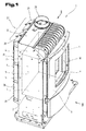
- a heater 1 is illustrated with technical measures to increase its operational reliability.
- This heating device 1 can be formed by any furnaces for combustion or for combustion of biomass.
- the heating device 1 may be formed by a so-called stove, which, among other things, also meets high aesthetic requirements.
- the corresponding biomass can be formed by any fuel in the form of wood, in particular by logs, pellets, or by wood chips.
- the heater 1 illustrated by way of example is designed in particular for the combinatory or alternating combustion or combustion of pellets and billets. It is essential that the heating device 1 primarily serves to provide heat in order to preferably heat living spaces with it.
- the corresponding heating device 1 is erected directly in the living area and emits appropriate heat by radiant heat or convective heat into the environment by heating to a corresponding extent the room or ambient air to the heater 1. It is also possible to assign the heater 1 warming trays or baking trays, or provide heat exchanger elements to allow hot water treatment for heating and / or service water.
- the heating device 1 comprises a substantially parallelepiped-shaped housing, in which a combustion chamber 2 for combustion of fuel based on biomass is formed.
- the combustion chamber 2 is delimited in the downward direction by a combustion chamber grate or by a combustion chamber bottom plate 3.
- the combustion chamber 2 is delimited by at least one combustion chamber cover plate 4, which combustion chamber cover plate 4 can also have a multi-part or stepped design or can also include inclinedly aligned sections.
- combustion chamber 2 is bounded by combustion chamber walls 5, which may also include refractory linings, in particular fireclay bricks.
- combustion chamber walls 5 which may also include refractory linings, in particular fireclay bricks.
- combustion chamber 2 has a rectangular cross-sectional outline contour
- two combustion chamber side walls 6, 7, a combustion chamber front wall 8 and a combustion chamber rear wall 9 opposite thereto are formed.
- the combustion chamber bottom plate 3 and the combustion chamber cover plate 4 can also be configured as multi-layered, in particular strength-relevant, metallic layers and refractory or high-temperature resistant cladding layers, for example of so-called fireclay bricks.
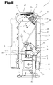
- the heating device 1 further comprises an at least partially automated or automatable fuel supply device 12, as best on Fig. 3 is apparent. This has at least one supply channel 13, 14 for automated or automatically regulated supply of free-flowing fuel.
- this fuel supply device 12 is designed for the automated supply of pellets or wood chips into the interior of the combustion chamber 2.
- This fuel supply device 12 comprises for this purpose in addition to the supply channels 13, 14 at least one reservoir 15, from which stored fuel, in particular a certain amount of pellets, in metered and automatically regulating amount via the at least one supply channel 13, 14 or via corresponding conveying devices the combustion chamber 2 can be supplied for thermal combustion.
- the free-flowing fuel in particular the combustion chamber 2 quasi portionwise or metered supplied pellet volume is conveyed into a combustion chamber depression 16.
- the respectively intended for combustion amount of fuel, in particular of pellets, containing the fuel supply device 12, in particular via various conveying devices, such as screw conveyors, for a regulated replenishment or for a sufficient tracking of pellets is taken care of in order to achieve adequate combustion with sufficient heating or heat output.
- the combustion chamber depression 16, which is designed to receive the pellets intended for combustion, is preferably in the center region of the combustion chamber base plate 3 positioned.
- the combustion chamber depression 16 which is designed as a bowl-like receiving body and has a plurality of openings for supplying combustion air into the receiving area of the combustion chamber depression 16, is recessed in relation to the upper side 17 of the combustion chamber base plate 3, as best seen in FIGS Fig. 3 is apparent.
- the bottom portion 18 of the combustion chamber Trough 16 is preferably designed as a about a horizontal pivot axis 20 rotatable or tiltable pellet grid 21.
- a manually initiated or automatically controlled tilting or swiveling of the pellet grid 21 may be provided, in order thereby to transfer or drop non-combustible residues or ashes into an ash tray or collecting tray positioned therebelow.
- the combustion chamber bottom plate 3 may have at its upper side 17 a plurality of distributed support studs 22.
- This support nubs 22 are used for increased support of billets against the substantially planar upper side 17 of the combustion chamber bottom plate 3.
- this support nips 22 it is achieved via this support nips 22, that the logs as evenly as possible flows around combustion air, especially the underside of the billet be acted upon with combustion air can.
- At least in a portion of the circumference at an upper opening 23 and the upper opening cross-section of the combustion chamber depression 16 at least one extension 24 is formed, which projects beyond the top 17 of the combustion chamber bottom plate 3.
- This at least one extension 24 is provided for increased support of logs above the substantially planar upper side 17 of the combustion chamber bottom plate 3.
- the at least one extension 24 enables a support of firewood directly above the opening 23 of the combustion chamber depression 16.
- the flue gases which are formed during the combustion of the logs deposited on the combustion chamber bottom plate 3 or in the combustion of pellets in the combustion chamber depression 16 are - as is known per se - continuously or discontinuously discharged from the combustion chamber 2.
- the heating device 1 comprises at least one outflow opening 25, which is provided for discharging the resulting from the combustion of biomass flue gases from the combustion chamber 2.
- This at least one outflow opening 25 is preferably positioned in the upper end section of the combustion chamber 2 or the housing of the heating device 1.
- the heater 1 comprises - as known per se - at least one flue gas outlet opening 26, which is provided for the transfer of the resulting combustion of biomass flue gases in a fireplace, not shown, or in a not shown, intermediate flue gas pipe.
- the flue gas outlet opening 26 is quasi the transfer interface for flue gas between the heater 1 and a peripheral discharge device, in particular a fireplace.
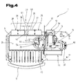
- At least one heat exchanger 27, in particular a so-called flue gas / ambient air heat exchanger 27 formed, as best of all Fig. 4 is apparent.
- This heat exchanger 27 is thus designed as a so-called gas / gas heat exchanger, after the heat transfer between different gaseous media, in particular between the flue gas and the ambient or room air has to be done.
- This at least one heat exchanger 27 is fluidically connected between the outflow opening 25 from the combustion chamber 2 and the flue gas outlet opening 26 from the heating device 1.
- the heat exchanger 27 is fluidically located between the outflow opening 25 and the flue gas outlet opening 26, wherein also intermediate transition or transfer or adaptation channel sections can be provided.
- the heat exchanger 27 forms at least one flue gas channel, through which flows the warm or hot flue gas and finally passed to the flue gas outlet opening 26 of the heater 1 to a chimney or chimney, or to an upstream pipeline.
- the heat exchanger 27 is used for the highest possible or effective extraction of heat energy from the guided through the flue gas channel, hot flue gases and for transmitting at least a portion of this heat energy to the ambient air of the heater 1.
- Heat exchanger 27 formed therein flue gas channels are in a variety of embodiments known from the prior art.
- the at least one flue gas duct of the heat exchanger comprises 27, a first channel section 28 and at least one further channel section 29.
- the first, vertically oriented channel section 28 and the at least one further, likewise vertically extending channel section 29, which directly adjoins the first or preceding channel section 28, are thereby connected in series in terms of flow.
- the inlet 30 for the flue gas and also in the upper end portion of the last channel portion 29 in the flow direction, the outlet 31 is formed for the guided through the flue of the heat exchanger 27 flue gases. This means that the flue gas, which is discharged from the combustion chamber 2 via the at least one outflow opening 25, is guided through the heat exchanger 27 in at least two directly successive vertical strokes.
- the flue gas flowing out of the combustion chamber 2 is guided in the upper end section of the combustion chamber 2 into the first channel section 28, guided downwards in the direction of the bottom of the heating device 1 and subsequently transferred into at least one further vertically oriented channel section 29 in which the flue gas is conducted starting from the bottom section in the upward direction, in particular in the direction of the upper end of the heating device 1. It is thus formed at least one fluidic counter-reaction in the heat exchanger 27 and in the vertical flue gas channels.
- the flue gas in the first channel section 28 is guided from top to bottom and transferred after a direction deflection in a second, serially adjoining channel section 29 and directed in this equally vertically oriented channel section 29 from bottom to top and at the end of this further channel section 29th passed through the outlet 31 directly or almost directly to the flue gas outlet opening 26, as best illustrated in the Fig. 3 and 4 can be seen.
- the construction costs in relation to the achievable efficiency are relatively optimal or particularly economical.
- At least one flue gas blower 32 is formed.
- This flue gas blower 32 which is a part of the heater 1, is used to build or accelerate a flue gas flow through the flue gas duct of the heat exchanger 27.
- This flue gas blower 32 can be threshold controlled, timed and / or speed controlled to build up the required volume flow can.
- a control device not shown, is provided, which regulates the combustion-related processes in such a way that the most optimal or efficient combustion process takes place.
- the flue gas fan 32 in particular the physical parameter negative pressure, which is regulatable or buildable by the flue gas fan 32 in the combustion chamber 2, is of importance.
- the supplied or sucked volume of combustion air or supply air can be automatically influenced or regulated via the negative pressure built up in the combustion chamber 2 by the flue gas fan 32.
- the flue gas blower 32 is positioned in a lower, ground-level or bottom-side transition section 33 between fluidically directly successive channel sections 28, 29, as is best known Fig. 3 is apparent.
- the transfer section 33 is formed by a substantially horizontally extending connecting channel 34, which connects two directly adjacent, vertically extending channel sections 28, 29 in terms of flow, so that the flue gas can pass from the first channel section 28 into the further channel section 29.
- the flue gas blower 32 is included in this transfer section 33. It is essential that the connecting channel 34, the lower and bottom ends of the first and the further channel portion 28 and 29 fluidly coupled together.
- the flue gas blower 32 is incorporated such that the suction side or negative pressure side of the flue gas blower 32 is connected via the first channel section 28 with the discharge opening 25 from the combustion chamber 2.
- the pressure or pressure side of the flue gas blower 32 via the at least one further channel section 29 with the flue gas outlet opening 26, which is downstream of the flue gas blower 32, fluidly connected.
- the flue gas outlet opening 26 is formed at the top or in the upper cover surface 35 of the housing of the heater 1, as best of Fig. 1 is apparent.
- the heat exchanger 27, in particular the first and the at least one further channel section 28, 29 of the flue gas duct is formed on a rear side of the heating device 1 facing away from the combustion chamber door 11 or with respect to the feed opening 10.
- the heat exchanger 27 and its channel sections 28, 29 are arranged on the back of the furnace housing, in particular on the combustion chamber rear wall 9, as best seen in a synopsis of Fig. 1 and 4 is apparent.
- the channel sections 28, 29 for forming the flue gas channel or for the implementation of the heat exchanger 27 by partially open in cross-section or unilaterally open, for example, by cross-sectionally substantially C- or U-shaped metal profiles 36, 37 are formed.
- the metal profiles 36, 37 in cross-section L-shaped, half-round or in the form of an omega sign.
- These metal profiles 36, 37 which are open on one side between the legs, form in connection with metallic wall sections of the furnace housing, in particular in connection with the combustion chamber rear wall 9 of the furnace housing, a gas-tight flue gas channel closed transversely to the flow direction of the flue gases.
- the C- or U-shaped metal profiles 36, 37 which may also be formed by elliptical or semicircular or polygonal in cross-section metal profiles, with the interposition of sealing elements with metallic wall sections, in particular with the metallic combustion chamber rear wall. 9 connected to the furnace housing.
- in cross-section preferably unilaterally open, for example C-, U-, E-, L- or omega-shaped metal profiles are screwed to the combustion chamber rear wall 9 of the furnace housing, as in Fig. 4 has been shown schematically.
- the metal profiles 36, 37 which ultimately define the heat exchanger 27, formed by independent components which are attached to the respective metallic wall surfaces of the heater 1, in particular bolted with the interposition of sealing elements.
- these metal profiles 36, 37 are formed from cast iron, in particular formed from gray cast iron.
- the vertically aligned, juxtaposed and fluidly connected in series flue gas ducts or the corresponding metal profiles 36, 37 extend almost over the entire height of the heater 1. It is favorable if a vertical extent of the flue gas ducts more than 50%, in particular more than 60%, preferably between 70% to 90%, the height of the heater 1 is. As a result, an optimized ratio between the construction volume or required space requirement and efficiency of the corresponding heat exchanger 27 can be achieved.
- heat-releasing webs 38, 39 are formed on at least one of the outer surfaces facing away from each other, for example C- or U-shaped metal profile 36, 37.
- These heat-releasing webs 38, 39 can be embodied as strip-like or knob-like and thus protrude from the channel sections 28, 29 or from its wall surfaces. The elements mentioned are used for surface enlargement or increase the heat transfer surface between the two gaseous media flue gas and ambient air.
- the heat release webs 38, 39 may be formed by a plurality of angularly aligned or wavy extending, integrally formed on the metal profile 36, 37 projections or nubs, as best shown in FIG Fig. 1 can be seen.
- a vertically extending air duct 41 for ambient air to be heated.
- a vertically extending air duct 41 is thereby formed between boundary surfaces 42, 43 of directly adjacent channel sections 28, 29 or between the corresponding metal profiles 36, 37.
- the back of the heater 1 may be provided with a cladding sheet or may be provided a the air duct 41 concrete delimiting air guide plate to achieve a defined flow for ambient air to be heated in the air duct 41.
- the heater 1 further comprises a supply air control device 44 for individually adjustable or automatically controlled reduction or increase in the volume of combustion air supplied.
- the supply air control device 44 is designed to reduce and increase a free passage cross-section for supplied supply air or for supplied primary and / or secondary air.
- at least one actuator is provided, which is adjustable by means of a manually operated by an operator handle.
- the supply air control device 44 is preferably also automatically adjustable, in particular controllable and adjustable by an electrotechnical control device, not shown.
- the negative pressure generated by the flue gas fan 32 in the combustion chamber 2 for the extraction of the flue gases produced during combustion also has an effect on the volume of combustion air or supply air supplied, so that the supply air control device 44 and the flue gas blower 32 are preferred be in control engineering interaction or controlled by a common or central control device and controlled accordingly or regulated.
- a preferred embodiment of the heating device 1 comprises a fuel supply device 12 for the metered, automatic supply of pellets into the combustion chamber depression 16, an automatically regulated supply air control device 44, a flue gas blower 32 and an electronic control device that controls these devices and is not shown.
- the heating device 1 is connected to an electrical energy supply source, in particular to the electrical energy supply network of a household.
- the heating device 1 is supplied or operated starting from a power supply network with a mains voltage of 230 V AC.
- the electrical energy from this standard power supply network is used primarily for operating the fuel supply device 12 and / or the automatically regulated supply air control device 44 and / or for operating or supplying the flue gas blower 32.
- the heat exchanger 27 with the relatively far-reaching or meandering flue gas ducts requires the implementation of a flue gas blower 32 for generating or maintaining a sufficient volume flow of flue gas or concomitantly supplying a sufficient amount of combustion air into the combustion chamber 2.
- a flue gas blower 32 for generating or maintaining a sufficient volume flow of flue gas or concomitantly supplying a sufficient amount of combustion air into the combustion chamber 2.
- At least one automatically or automatically adjustable actuator 45 is provided.
- Fig. 2 - Provided, which is associated with the flue gas channel of the heat exchanger 27 or the combustion chamber 2 and designed such that the actuator 45 is automatically switched in case of failure or interruption of the electrical operating or supply energy of the heater 1 or the flue gas blower 32 such that a flow path of the Flue gas starting from the combustion chamber 2 is shortened to the flue gas outlet opening 26 or will.
- the at least one automatically or automatically umstell- or adjustable actuator 45 may also be designed such that it is automatically switched in case of failure or interruption of the electrical operating or supply energy of the heater 1 or the flue gas blower 32, that the flow path through the Flue gas duct of a heat exchanger 27 via a released by the actuator 45 by-pass opening 46 is at least abbreviated or completely bypassed.
- the heating device 1 it is expedient to design the heating device 1 such that a flow resistance for the flue gas in the direction of the flue gas outlet opening 26 via the releasable by the actuator 45 in case of power failure or power interruption bypass opening 46 is less than via the flow path through the flue gas duct of the heat exchanger 27.
- this actuator 45 which is preferably designed as a butterfly valve or as a control slide, a bypass of the flow paths or flue gas channels of the heat exchanger 27 allows. In this case, either a complete bypass or only a partial bypass, that is, a shortening of the flue gas paths within the heat exchanger 27 is possible.
- the actuator 45 is designed and stored so that it in case of failure or interruption of the electrical operating or supply energy of the heater 1 total, or in particular with respect to the electrical supply of the flue gas blower 32, automatically, that is without manual In this case, an opening position releasing the bypass opening 46 is / is transferred.
- the bypass opening 46 is positioned or arranged such that in the open position of the actuator 45, the shortest possible or a relatively short connection between the at least one outflow opening 25 from the combustion chamber 2 and the flue gas outlet opening 26 is made or released.
- the bypass opening 46 is embodied in the upper end section of the combustion chamber 2, in particular in the combustion chamber cover plate 4 and / or in the upper end section of the combustion chamber side walls 6, 7 and / or in the combustion chamber rear wall 9 executed.
- a relatively direct discharge of the flue gases from the combustion chamber 2 in the direction of the flue gas outlet opening 26 is ensured without the flue gas having to be forced over the flue gas channels of the heat exchanger 27.
- the bypass opening 46 is opened, a flue gas discharge via the more direct or shorter path with relatively low flow resistance in the direction of the flue gas outlet opening 26 will occur.
- the actuator 45 is urged by spring force or under the action of gravity steadily in the direction of the bypass opening 46 releasing opening position.
- This spring force or gravitational force acting on the actuator 45 counteracts a counter or holding force built up by the electrical operating or supply energy.
- an electromagnetic holding force is provided which keeps the actuator 45 in its closed position during the presence of electrical operating or supply energy for the heating device 1 or for the flue gas blower 32.
- Corresponding actuating or spring force for the automated opening or release of the bypass opening 46 can be provided in a simple manner by a spring means 47, for example by a helical spring, spiral spring or by a leaf spring.
- the spring means 47 is mounted for example between a lever 48 on the actuator 45 and a housing-fixed anchoring point 49 or under bias between them.
- a lever 48 on the actuator 45 and a housing-fixed anchoring point 49 or under bias between them.
- gravity for example by additional weights or by eccentric bearings for the actuator 45 to exert a force on the actuator 45 so that it is constantly or permanently forced into a bypass opening 46 releasing opening position .
- the holding force which counteracts this spring force or gravitational force and holds in the presence of electrical operating or supply energy, the actuator 45 in its closed position, is preferably by electromagnetic holding force constructed or provided indirectly by electromagnetic holding power or guaranteed.
- At least one electromagnet 50 which, in the active state, directly or indirectly applies or ensures the corresponding holding force, which counteracts the spring force or the action of gravity and cancels these forces.
- This electromagnet 50 can be activated in a simple manner in the presence of electrical operating or supply energy to the heater 1 and the flue gas fan 32, that is acted upon by corresponding electrical energy and thus hold the actuator 45 in the closed position, so the bypass opening 46 remains closed and the flue gas is passed through the heat exchanger 27.
- the electromagnet 50 or an interposed locking device 52 loses its holding force, whereupon the actuator 45 is transferred directly into an open position releasing the bypass opening. This transfer into the open position preferably takes place without current, in particular via the corresponding actuating force of the spring means 47 or gravity.
- the electromagnet 50 can be connected directly to the supply voltage for the heating device 1 or to the supply voltage for the flue gas blower 32 in a simple manner. But it is of course also possible to provide an electrical or electronic monitoring device which monitors the presence of the electrical operating or supply voltage or which monitors the function of the flue gas fan 32 and the Zu Kunststoff Kunststoffvoriques 44 and the fuel delivery device 12 and the electromagnet 50 in case of malfunction deactivated so that the actuator 45 introduces the flue gas discharge on a short path via the bypass port 46.
- the kinematic or mechanical couplings between the electromagnet 50 and the actuator 45 are within the skill of the art. In particular, a plurality of motion transmission mechanisms are conceivable to switch the actuator 45 in dependence on the operating state of the electromagnet 50 or to adjust.
- a linkage 51 is provided, which initiates or releases an immediate opening movement of the actuator 45 when the electromagnet 50 falls.
- the electromagnet 50 may in particular be formed by a tie rod magnet or by a so-called electro-adhesion magnet.
- the actuator 45 by a manual operation against the force of the spring force or against a force of gravity in the Closing position is transferred or is traceable, provided and as long as electrical operating or supply energy is present at the heater 1 and is ready to supply the flue gas blower 32.
- the actuator 45 is aware of the user, in particular by a manual operator action to be transferred back to the closed position. In this closed position, the bypass opening 46 is closed or sufficiently gastight.
- maintaining this closure position is only ensured if electrical power is supplied, in particular the corresponding electrical operating or supply energy is present at the heating device 1 or is available for the flue gas blower 32 or its control. Only when the electromagnet 50 is activated or has attracted, can a locking or locking of the actuator 45 take place in its closed position.
- a locking device 52 is provided, which is preferably formed by a latching device comprising at least one pawl or at least one latching tooth.
- the solenoid 50 is activated, that is supplied with electrical energy, and the locking device 52 can be active and hold the actuator 45 in its closed position.
- the solenoid 50 drops, whereupon the locking device 52 is released and the actuator 45 is automatically transferred to its open position or jumps up.
- the electromagnet 50 direct or indirect influence on the active and inactive state of the locking device 52, wherein the locking device 52 subsequently has an influence on the position of the actuator 45.
- the actuator 45 by incorporating a mechanical locking device 52 exert a high pressure or sealing force against the edge region around the bypass opening, without these high contact pressure or sealing forces permanently from the electromagnet 50, in particular from a corresponding, electrical tie rods - Or magnets should be applied.
- a controlled releasable locking device 52 significant functional and energy advantages can be achieved.
- the actuator 45 is designed as a adjustably mounted about a pivot axis 53 control valve 54.
- the adjusting flap 54 is pivotable in dependence on the presence and absence of electrical operating or supply energy for the flue gas blower 32 or for the heating device 1 between its closed position and its open position - and vice versa.
- the valve 54 is held in the presence of electrical operating or supply energy in a bypass opening 46 occluding position, while in case of failure or elimination of the electrical operating or supply energy, the valve 54 is pivoted up or away and the bypass port 46th thus releases.
- the actuator 45 which is designed for example in the form of a valve 54, and released in case of power failure bypass port 46 are positioned in the upper end portion of the combustion chamber 2, and that in the open position of the actuator 45, a transition of flue gas to the flue gas outlet opening 26 takes place without the assistance of the flue gas fan 32, in particular solely by thermal convection of the flue gas or guaranteed.
- the Umstell- or movement command of the actuator 45 is thus derived from an electromagnet 50 or directly or indirectly defined by a Elektrohaftmagneten.
- a power failure or a power interruption is reliably detected via the position of an electromagnet 50 or a tie rod magnet, whereupon the corresponding measure, in particular the release of the bypass opening 46, is initiated in a simple and reliable manner.
- At least one blocking element 55 is formed on the generic heating device 1, which is assigned to the automatic fuel supply device 12.
- the at least one blocking element 55 is assigned to at least one feed channel 12, 13 of the fuel feed device 12 and is designed to prevent or fire-resistant separation or interruption of at least one feed channel 13, 14.
- at least one supply channel 13, 14 associated with at least one blocking element 55 which is designed such that it automatically in case of failure or interruption of the electrical operating or supply energy of the flue gas blower 32 and / or the heater 1 and / or an electromotive drive device of the fuel supply device 12 is switched so that at least one supply channel 12, 13 is shut off mechanically for fuel.
- This mechanical shut-off by the blocking element 55 is implemented such that a mechanical interruption or a non-combustible separation in at least one supply channel 12, 13 is formed or produced for the free-flowing fuel.
- the fuel supply device 12 comprises a first conveyor 56, which is preferably associated with the first supply channel 13.
- This first conveying device 56 preferably comprises a conveying screw for free-flowing material.
- the first conveying device 56 serves to transport fuel, in particular pellets, from the reservoir 15 into a further, downstream conveying device 57.
- This further conveying device 57 which preferably also comprises a conveying screw and a corresponding electromotive driving device, is preferably a lateral insertion system for the combustion chamber.
- This further conveying device 57 is assigned to the further supply channel 14 or represents this further conveying device 57 is a component of the further supply channel 14.
- the further conveyor 57 serves in any case for further promotion of fuel into the combustion chamber 2 and into the combustion chamber recess 16 within the combustion chamber second
- the blocking element 55 is designed as a locking slide 59.
- a locking slide 59 is preferably mounted linearly adjustable, but may also be mounted rotationally.
- the blocking element 55 or its blocking slide 59 is expediently urged by spring force or under the action of gravity into a closed position interrupting the fuel supply or the chute 58.
- spring means 60 is provided. It is essential that the spring-loaded locking element 55 and the standing under gravity blocking element 55 by means of a by the electrical operating or supply energy of the heater 1 directly or indirectly constructed holding force, in particular by an electromagnetic holding force, in the open position, that is in one of Fuel supply or the chute 58 is held releasing position.
- the blocking element 55 is held in the open position during the presence of electrical operating or supply energy for the heating device 1 or for the flue gas blower 32 or for the fuel supply device 12.
- the electromagnetic holding force is reduced, whereupon the blocking element 55 immediately in its the fuel supply or the Falling shaft 58 closing position is transferred. This is accomplished by the biased spring means 60 and by gravity, respectively.
- a single solenoid 50 is formed, which in its electromagnetic active state, the closed position of the actuator 45 described above and at the same time ensures the open position of the blocking element 55 and converts.
- a mechanical movement coupling is carried out, which acts both on the blocking element 55, and on the actuator 45.
- the corresponding mechanics for motion coupling are familiar to the expert and this is a variety of designs possible.
- the locking member 55 and the locking slide 59 is only then in its release or open position with respect to the chute 58 and with respect to the fuel supply device 12 can be transferred as soon as the electrical operating or supply energy for proper implementation of the planned function or Operation of the heater 1 is present.
- a manually operated handle 61 is formed.
- This handle 61 is to be actively operated by the operator, for example, to pivot to close the bypass opening 46 and to release the chute 58.
- a permanent closed position or release position is only achieved or ensured if the electrical operating and / or supply energy for the heating device 1 is present, which is preferably detected or detected via at least one electromagnet 50.
- the handle 61 is to be adjusted by the operator against the force of gravity or against the spring force of the spring means 47 and 60, respectively. As a result, the spring or biasing action of the spring means 47 and 60 is quasi activated again and thus stands for an automatically triggered, currentless adjustment of the actuator 45 and the blocking element 55 available as soon as an interruption or failure of the operating or supply energy occurs ,
- the Zu poverty horrinvorraum 56 form such that both an automated Zubuchregulierung an electronic control device of the heater 1, as well as a manual influence on the Zu poverty horrinvorraum 56 is possible.
- the automated and manual adjustability of the supply air control device 56 can be provided alternatively or in combination. In particular, in the case of a prolonged failure or interruption of the electrical operating or supply energy for the heating device 1, a completely manual operating mode or an emergency operation is available, in which a trouble-free heating operation with manually fed firewood can take place with the indicated heating device 1.
Landscapes
- Engineering & Computer Science (AREA)
- Chemical & Material Sciences (AREA)
- Combustion & Propulsion (AREA)
- Mechanical Engineering (AREA)
- General Engineering & Computer Science (AREA)
- Physics & Mathematics (AREA)
- Thermal Sciences (AREA)
- Air Supply (AREA)
- Solid-Fuel Combustion (AREA)
Applications Claiming Priority (1)
| Application Number | Priority Date | Filing Date | Title |
|---|---|---|---|
| ATA349/2011A AT511576B1 (de) | 2011-03-14 | 2011-03-14 | Heizeinrichtung zur verbrennung von biomasse |
Publications (3)
| Publication Number | Publication Date |
|---|---|
| EP2500652A2 true EP2500652A2 (fr) | 2012-09-19 |
| EP2500652A3 EP2500652A3 (fr) | 2017-06-07 |
| EP2500652B1 EP2500652B1 (fr) | 2018-09-05 |
Family
ID=45894159
Family Applications (1)
| Application Number | Title | Priority Date | Filing Date |
|---|---|---|---|
| EP12159253.9A Active EP2500652B1 (fr) | 2011-03-14 | 2012-03-13 | Dispositif de chauffage destiné à la combustion de biomasse |
Country Status (2)
| Country | Link |
|---|---|
| EP (1) | EP2500652B1 (fr) |
| AT (1) | AT511576B1 (fr) |
Citations (1)
| Publication number | Priority date | Publication date | Assignee | Title |
|---|---|---|---|---|
| DE19633755A1 (de) | 1995-08-24 | 1997-02-27 | Karl Stefan Riener | Ofen für feste Brennstoffe sowie Steuerverfahren für einen solchen Ofen |
Family Cites Families (8)
| Publication number | Priority date | Publication date | Assignee | Title |
|---|---|---|---|---|
| US2252046A (en) * | 1938-10-17 | 1941-08-12 | William L Steele | Furnace |
| US3507256A (en) * | 1968-08-26 | 1970-04-21 | Konus Kessel Ges Fur Warmetech | Forced-circulation boiler system with separate boiler and furnace |
| FR2475707A1 (en) * | 1980-02-07 | 1981-08-14 | Sevelen Metallbau | Heat exchanger housing inserted between two sections of exhaust - recovers waste heat with by=pass regulated via temp. sensors and computing mechanism |
| US4856438A (en) * | 1988-03-14 | 1989-08-15 | Dean Peugh | Furnace |
| CA2082915C (fr) * | 1992-11-13 | 1995-08-08 | Wolfgang Schroeter | Registre d'ete pour foyer |
| CA2494239C (fr) * | 2000-08-07 | 2005-11-15 | Woodlane Environmental Technology, Inc. | Systeme et methode de ventilation |
| EP1653154A1 (fr) * | 2004-11-02 | 2006-05-03 | Rüegg Cheminée AG | Cheminée |
| DE102013019954A1 (de) * | 2013-11-27 | 2015-05-28 | Karl Stefan Riener | Ofen zur Wärmeerzeugung |
-
2011
- 2011-03-14 AT ATA349/2011A patent/AT511576B1/de active
-
2012
- 2012-03-13 EP EP12159253.9A patent/EP2500652B1/fr active Active
Patent Citations (1)
| Publication number | Priority date | Publication date | Assignee | Title |
|---|---|---|---|---|
| DE19633755A1 (de) | 1995-08-24 | 1997-02-27 | Karl Stefan Riener | Ofen für feste Brennstoffe sowie Steuerverfahren für einen solchen Ofen |
Also Published As
| Publication number | Publication date |
|---|---|
| EP2500652B1 (fr) | 2018-09-05 |
| AT511576B1 (de) | 2013-03-15 |
| AT511576A1 (de) | 2012-12-15 |
| EP2500652A3 (fr) | 2017-06-07 |
Similar Documents
| Publication | Publication Date | Title |
|---|---|---|
| EP1022512A1 (fr) | Four de cuisson ou de boulanger utilisant des boulettes de combustible | |
| EP2228603A2 (fr) | Procédé de réglage de la puissance d'un four à carburant solide et four doté d'un réglage de la puissance correspondant | |
| EP2500650A2 (fr) | Procédé de réglage d'un dispositif de chauffage | |
| EP2500658B1 (fr) | Dispositif de chauffage comprenant une chambre de combustion destinée à la combustion de matériau combustible à base de biomasse | |
| DE10254565B4 (de) | Kaminofen und seine Verwendung | |
| DE3882505T2 (de) | Verbrennungsverfahren mit schneller Auslösung und Mittel zu dessen Durchführung in einer Heiz- und Verbrennungsvorrichtung. | |
| EP0038962A1 (fr) | Dispositif pour la combustion de matières solides légères par un foyer à chargement continu | |
| EP2500652B1 (fr) | Dispositif de chauffage destiné à la combustion de biomasse | |
| CH658711A5 (de) | Zugbegrenzer- und belueftungsanordnung an einer feuerstaette. | |
| AT505521A1 (de) | Vorrichtung zum verbrennen von festbrennstoffelementen | |
| EP2096356A2 (fr) | Four | |
| EP1850071A2 (fr) | Four avec une amenée d'air primaire et procédé de fonctionnement d'un tel four | |
| EP2775201B1 (fr) | Procédé de fonctionnement d'un appareil de chauffage | |
| EP2551591A2 (fr) | Commande de l'air d'alimentation pour un dispositif de chauffage | |
| EP1113223B1 (fr) | Appareil de combustion | |
| AT502492B1 (de) | Ofen für festbrennstoffe | |
| EP3361152B1 (fr) | Four à biomasse | |
| EP4375570B1 (fr) | Installation de chauffage de biomasse à nettoyage amélioré et détection de blocage de celle-ci | |
| DE202007011469U1 (de) | Pelletbrenner für Bäckereiöfen | |
| EP1832814A2 (fr) | Four avec entrée d'air secondaire | |
| DE56910C (de) | Feuerungsanlage | |
| DE102012001123A1 (de) | Vorrichtung zum Verbrennen von Brennstoffen | |
| AT411793B (de) | Heizeinsatz | |
| DE2517199A1 (de) | Krematoriumsofen | |
| DE3339689A1 (de) | Feuerungsanlage zur verbrennung von pulver- oder granulatfoermigen stoffen |
Legal Events
| Date | Code | Title | Description |
|---|---|---|---|
| PUAI | Public reference made under article 153(3) epc to a published international application that has entered the european phase |
Free format text: ORIGINAL CODE: 0009012 |
|
| AK | Designated contracting states |
Kind code of ref document: A2 Designated state(s): AL AT BE BG CH CY CZ DE DK EE ES FI FR GB GR HR HU IE IS IT LI LT LU LV MC MK MT NL NO PL PT RO RS SE SI SK SM TR |
|
| AX | Request for extension of the european patent |
Extension state: BA ME |
|
| PUAL | Search report despatched |
Free format text: ORIGINAL CODE: 0009013 |
|
| AK | Designated contracting states |
Kind code of ref document: A3 Designated state(s): AL AT BE BG CH CY CZ DE DK EE ES FI FR GB GR HR HU IE IS IT LI LT LU LV MC MK MT NL NO PL PT RO RS SE SI SK SM TR |
|
| AX | Request for extension of the european patent |
Extension state: BA ME |
|
| RIC1 | Information provided on ipc code assigned before grant |
Ipc: F23B 80/04 20060101ALI20170502BHEP Ipc: F24B 5/02 20060101ALI20170502BHEP Ipc: F23N 5/24 20060101AFI20170502BHEP |
|
| PUAL | Search report despatched |
Free format text: ORIGINAL CODE: 0009013 |
|
| STAA | Information on the status of an ep patent application or granted ep patent |
Free format text: STATUS: REQUEST FOR EXAMINATION WAS MADE |
|
| 17P | Request for examination filed |
Effective date: 20171205 |
|
| RBV | Designated contracting states (corrected) |
Designated state(s): AL AT BE BG CH CY CZ DE DK EE ES FI FR GB GR HR HU IE IS IT LI LT LU LV MC MK MT NL NO PL PT RO RS SE SI SK SM TR |
|
| GRAP | Despatch of communication of intention to grant a patent |
Free format text: ORIGINAL CODE: EPIDOSNIGR1 |
|
| STAA | Information on the status of an ep patent application or granted ep patent |
Free format text: STATUS: GRANT OF PATENT IS INTENDED |
|
| INTG | Intention to grant announced |
Effective date: 20180503 |
|
| GRAS | Grant fee paid |
Free format text: ORIGINAL CODE: EPIDOSNIGR3 |
|
| GRAA | (expected) grant |
Free format text: ORIGINAL CODE: 0009210 |
|
| STAA | Information on the status of an ep patent application or granted ep patent |
Free format text: STATUS: THE PATENT HAS BEEN GRANTED |
|
| AK | Designated contracting states |
Kind code of ref document: B1 Designated state(s): AL AT BE BG CH CY CZ DE DK EE ES FI FR GB GR HR HU IE IS IT LI LT LU LV MC MK MT NL NO PL PT RO RS SE SI SK SM TR |
|
| REG | Reference to a national code |
Ref country code: GB Ref legal event code: FG4D Free format text: NOT ENGLISH |
|
| REG | Reference to a national code |
Ref country code: CH Ref legal event code: EP |
|
| REG | Reference to a national code |
Ref country code: AT Ref legal event code: REF Ref document number: 1038258 Country of ref document: AT Kind code of ref document: T Effective date: 20180915 |
|
| REG | Reference to a national code |
Ref country code: IE Ref legal event code: FG4D Free format text: LANGUAGE OF EP DOCUMENT: GERMAN |
|
| REG | Reference to a national code |
Ref country code: DE Ref legal event code: R096 Ref document number: 502012013358 Country of ref document: DE |
|
| REG | Reference to a national code |
Ref country code: CH Ref legal event code: NV Representative=s name: ABP PATENT NETWORK AG, CH |
|
| REG | Reference to a national code |
Ref country code: NL Ref legal event code: MP Effective date: 20180905 |
|
| REG | Reference to a national code |
Ref country code: LT Ref legal event code: MG4D |
|
| REG | Reference to a national code |
Ref country code: SE Ref legal event code: TRGR |
|
| PG25 | Lapsed in a contracting state [announced via postgrant information from national office to epo] |
Ref country code: BG Free format text: LAPSE BECAUSE OF FAILURE TO SUBMIT A TRANSLATION OF THE DESCRIPTION OR TO PAY THE FEE WITHIN THE PRESCRIBED TIME-LIMIT Effective date: 20181205 Ref country code: LT Free format text: LAPSE BECAUSE OF FAILURE TO SUBMIT A TRANSLATION OF THE DESCRIPTION OR TO PAY THE FEE WITHIN THE PRESCRIBED TIME-LIMIT Effective date: 20180905 Ref country code: FI Free format text: LAPSE BECAUSE OF FAILURE TO SUBMIT A TRANSLATION OF THE DESCRIPTION OR TO PAY THE FEE WITHIN THE PRESCRIBED TIME-LIMIT Effective date: 20180905 Ref country code: RS Free format text: LAPSE BECAUSE OF FAILURE TO SUBMIT A TRANSLATION OF THE DESCRIPTION OR TO PAY THE FEE WITHIN THE PRESCRIBED TIME-LIMIT Effective date: 20180905 Ref country code: NO Free format text: LAPSE BECAUSE OF FAILURE TO SUBMIT A TRANSLATION OF THE DESCRIPTION OR TO PAY THE FEE WITHIN THE PRESCRIBED TIME-LIMIT Effective date: 20181205 Ref country code: GR Free format text: LAPSE BECAUSE OF FAILURE TO SUBMIT A TRANSLATION OF THE DESCRIPTION OR TO PAY THE FEE WITHIN THE PRESCRIBED TIME-LIMIT Effective date: 20181206 |
|
| PG25 | Lapsed in a contracting state [announced via postgrant information from national office to epo] |
Ref country code: LV Free format text: LAPSE BECAUSE OF FAILURE TO SUBMIT A TRANSLATION OF THE DESCRIPTION OR TO PAY THE FEE WITHIN THE PRESCRIBED TIME-LIMIT Effective date: 20180905 Ref country code: HR Free format text: LAPSE BECAUSE OF FAILURE TO SUBMIT A TRANSLATION OF THE DESCRIPTION OR TO PAY THE FEE WITHIN THE PRESCRIBED TIME-LIMIT Effective date: 20180905 Ref country code: AL Free format text: LAPSE BECAUSE OF FAILURE TO SUBMIT A TRANSLATION OF THE DESCRIPTION OR TO PAY THE FEE WITHIN THE PRESCRIBED TIME-LIMIT Effective date: 20180905 |
|
| PG25 | Lapsed in a contracting state [announced via postgrant information from national office to epo] |
Ref country code: RO Free format text: LAPSE BECAUSE OF FAILURE TO SUBMIT A TRANSLATION OF THE DESCRIPTION OR TO PAY THE FEE WITHIN THE PRESCRIBED TIME-LIMIT Effective date: 20180905 Ref country code: EE Free format text: LAPSE BECAUSE OF FAILURE TO SUBMIT A TRANSLATION OF THE DESCRIPTION OR TO PAY THE FEE WITHIN THE PRESCRIBED TIME-LIMIT Effective date: 20180905 Ref country code: ES Free format text: LAPSE BECAUSE OF FAILURE TO SUBMIT A TRANSLATION OF THE DESCRIPTION OR TO PAY THE FEE WITHIN THE PRESCRIBED TIME-LIMIT Effective date: 20180905 Ref country code: NL Free format text: LAPSE BECAUSE OF FAILURE TO SUBMIT A TRANSLATION OF THE DESCRIPTION OR TO PAY THE FEE WITHIN THE PRESCRIBED TIME-LIMIT Effective date: 20180905 Ref country code: CZ Free format text: LAPSE BECAUSE OF FAILURE TO SUBMIT A TRANSLATION OF THE DESCRIPTION OR TO PAY THE FEE WITHIN THE PRESCRIBED TIME-LIMIT Effective date: 20180905 Ref country code: IS Free format text: LAPSE BECAUSE OF FAILURE TO SUBMIT A TRANSLATION OF THE DESCRIPTION OR TO PAY THE FEE WITHIN THE PRESCRIBED TIME-LIMIT Effective date: 20190105 Ref country code: PL Free format text: LAPSE BECAUSE OF FAILURE TO SUBMIT A TRANSLATION OF THE DESCRIPTION OR TO PAY THE FEE WITHIN THE PRESCRIBED TIME-LIMIT Effective date: 20180905 |
|
| PG25 | Lapsed in a contracting state [announced via postgrant information from national office to epo] |
Ref country code: SK Free format text: LAPSE BECAUSE OF FAILURE TO SUBMIT A TRANSLATION OF THE DESCRIPTION OR TO PAY THE FEE WITHIN THE PRESCRIBED TIME-LIMIT Effective date: 20180905 Ref country code: PT Free format text: LAPSE BECAUSE OF FAILURE TO SUBMIT A TRANSLATION OF THE DESCRIPTION OR TO PAY THE FEE WITHIN THE PRESCRIBED TIME-LIMIT Effective date: 20190105 Ref country code: SM Free format text: LAPSE BECAUSE OF FAILURE TO SUBMIT A TRANSLATION OF THE DESCRIPTION OR TO PAY THE FEE WITHIN THE PRESCRIBED TIME-LIMIT Effective date: 20180905 |
|
| PGFP | Annual fee paid to national office [announced via postgrant information from national office to epo] |
Ref country code: SI Payment date: 20190227 Year of fee payment: 9 |
|
| REG | Reference to a national code |
Ref country code: DE Ref legal event code: R097 Ref document number: 502012013358 Country of ref document: DE |
|
| PLBE | No opposition filed within time limit |
Free format text: ORIGINAL CODE: 0009261 |
|
| STAA | Information on the status of an ep patent application or granted ep patent |
Free format text: STATUS: NO OPPOSITION FILED WITHIN TIME LIMIT |
|
| PG25 | Lapsed in a contracting state [announced via postgrant information from national office to epo] |
Ref country code: DK Free format text: LAPSE BECAUSE OF FAILURE TO SUBMIT A TRANSLATION OF THE DESCRIPTION OR TO PAY THE FEE WITHIN THE PRESCRIBED TIME-LIMIT Effective date: 20180905 |
|
| 26N | No opposition filed |
Effective date: 20190606 |
|
| PG25 | Lapsed in a contracting state [announced via postgrant information from national office to epo] |
Ref country code: SI Free format text: LAPSE BECAUSE OF FAILURE TO SUBMIT A TRANSLATION OF THE DESCRIPTION OR TO PAY THE FEE WITHIN THE PRESCRIBED TIME-LIMIT Effective date: 20180905 |
|
| PG25 | Lapsed in a contracting state [announced via postgrant information from national office to epo] |
Ref country code: MC Free format text: LAPSE BECAUSE OF FAILURE TO SUBMIT A TRANSLATION OF THE DESCRIPTION OR TO PAY THE FEE WITHIN THE PRESCRIBED TIME-LIMIT Effective date: 20180905 |
|
| GBPC | Gb: european patent ceased through non-payment of renewal fee |
Effective date: 20190313 |
|
| PG25 | Lapsed in a contracting state [announced via postgrant information from national office to epo] |
Ref country code: LU Free format text: LAPSE BECAUSE OF NON-PAYMENT OF DUE FEES Effective date: 20190313 |
|
| PG25 | Lapsed in a contracting state [announced via postgrant information from national office to epo] |
Ref country code: IE Free format text: LAPSE BECAUSE OF NON-PAYMENT OF DUE FEES Effective date: 20190313 Ref country code: GB Free format text: LAPSE BECAUSE OF NON-PAYMENT OF DUE FEES Effective date: 20190313 |
|
| PG25 | Lapsed in a contracting state [announced via postgrant information from national office to epo] |
Ref country code: FR Free format text: LAPSE BECAUSE OF NON-PAYMENT OF DUE FEES Effective date: 20190331 |
|
| PG25 | Lapsed in a contracting state [announced via postgrant information from national office to epo] |
Ref country code: TR Free format text: LAPSE BECAUSE OF FAILURE TO SUBMIT A TRANSLATION OF THE DESCRIPTION OR TO PAY THE FEE WITHIN THE PRESCRIBED TIME-LIMIT Effective date: 20180905 |
|
| PG25 | Lapsed in a contracting state [announced via postgrant information from national office to epo] |
Ref country code: MT Free format text: LAPSE BECAUSE OF FAILURE TO SUBMIT A TRANSLATION OF THE DESCRIPTION OR TO PAY THE FEE WITHIN THE PRESCRIBED TIME-LIMIT Effective date: 20180905 |
|
| PG25 | Lapsed in a contracting state [announced via postgrant information from national office to epo] |
Ref country code: SE Free format text: LAPSE BECAUSE OF NON-PAYMENT OF DUE FEES Effective date: 20200314 |
|
| PG25 | Lapsed in a contracting state [announced via postgrant information from national office to epo] |
Ref country code: CY Free format text: LAPSE BECAUSE OF FAILURE TO SUBMIT A TRANSLATION OF THE DESCRIPTION OR TO PAY THE FEE WITHIN THE PRESCRIBED TIME-LIMIT Effective date: 20180905 |
|
| PG25 | Lapsed in a contracting state [announced via postgrant information from national office to epo] |
Ref country code: HU Free format text: LAPSE BECAUSE OF FAILURE TO SUBMIT A TRANSLATION OF THE DESCRIPTION OR TO PAY THE FEE WITHIN THE PRESCRIBED TIME-LIMIT; INVALID AB INITIO Effective date: 20120313 |
|
| PG25 | Lapsed in a contracting state [announced via postgrant information from national office to epo] |
Ref country code: MK Free format text: LAPSE BECAUSE OF FAILURE TO SUBMIT A TRANSLATION OF THE DESCRIPTION OR TO PAY THE FEE WITHIN THE PRESCRIBED TIME-LIMIT Effective date: 20180905 |
|
| PGFP | Annual fee paid to national office [announced via postgrant information from national office to epo] |
Ref country code: IT Payment date: 20250306 Year of fee payment: 14 |
|
| PGFP | Annual fee paid to national office [announced via postgrant information from national office to epo] |
Ref country code: CH Payment date: 20250429 Year of fee payment: 14 |
|
| PGFP | Annual fee paid to national office [announced via postgrant information from national office to epo] |
Ref country code: DE Payment date: 20260320 Year of fee payment: 15 |
|
| PGFP | Annual fee paid to national office [announced via postgrant information from national office to epo] |
Ref country code: AT Payment date: 20260320 Year of fee payment: 15 |
|
| PGFP | Annual fee paid to national office [announced via postgrant information from national office to epo] |
Ref country code: BE Payment date: 20260316 Year of fee payment: 15 |