EP2500751B1 - Dispositif et procédé de mesure à distance de la hauteur des précipitations par drainage par siphon à fonction d'auto-compensation - Google Patents
Dispositif et procédé de mesure à distance de la hauteur des précipitations par drainage par siphon à fonction d'auto-compensation Download PDFInfo
- Publication number
- EP2500751B1 EP2500751B1 EP10827849.0A EP10827849A EP2500751B1 EP 2500751 B1 EP2500751 B1 EP 2500751B1 EP 10827849 A EP10827849 A EP 10827849A EP 2500751 B1 EP2500751 B1 EP 2500751B1
- Authority
- EP
- European Patent Office
- Prior art keywords
- rainfall
- water level
- siphon
- measuring tube
- siphon drainage
- Prior art date
- Legal status (The legal status is an assumption and is not a legal conclusion. Google has not performed a legal analysis and makes no representation as to the accuracy of the status listed.)
- Active
Links
- 238000000034 method Methods 0.000 title claims description 36
- 238000005259 measurement Methods 0.000 title claims description 25
- XLYOFNOQVPJJNP-UHFFFAOYSA-N water Substances O XLYOFNOQVPJJNP-UHFFFAOYSA-N 0.000 claims description 58
- 230000003321 amplification Effects 0.000 claims description 16
- 238000001914 filtration Methods 0.000 claims description 16
- 238000003199 nucleic acid amplification method Methods 0.000 claims description 16
- 230000005540 biological transmission Effects 0.000 claims description 8
- 230000000630 rising effect Effects 0.000 claims description 8
- 238000006243 chemical reaction Methods 0.000 claims description 7
- 125000004122 cyclic group Chemical group 0.000 description 2
- 238000010586 diagram Methods 0.000 description 2
- 230000008054 signal transmission Effects 0.000 description 2
- 238000004458 analytical method Methods 0.000 description 1
- 238000009530 blood pressure measurement Methods 0.000 description 1
- 238000004364 calculation method Methods 0.000 description 1
- 238000005265 energy consumption Methods 0.000 description 1
- 230000007774 longterm Effects 0.000 description 1
- 238000004519 manufacturing process Methods 0.000 description 1
- 230000002265 prevention Effects 0.000 description 1
- 230000002123 temporal effect Effects 0.000 description 1
Images
Classifications
-
- G—PHYSICS
- G01—MEASURING; TESTING
- G01W—METEOROLOGY
- G01W1/00—Meteorology
- G01W1/14—Rainfall or precipitation gauges
Definitions
- the present invention relates to rainfall measurement, and particularly to a method and apparatus for the remote siphon drainage type rainfall measurement with self-compensation function.
- Rainfall measurement is needed in the fields of meteorology, water conservation, geological disaster prevention, etc.
- the existing apparatus for remote automatic rainfall measurement uses a tipping bucket sensor, but its accuracy is relatively low, and the measurement error is typically ⁇ 4%.
- the existing apparatus for the siphon drainage type rainfall measurement relies on a paper-tape recording equipment with mechanical mechanism, which needs workers arrive at the scene to observe the recorded plot on the paper-tape to obtain the amount of rainfall, and its measurement error is ⁇ 2%.
- the message on the paper can not be transmitted remotely. Therefore, there is a need for a method and apparatus for remote measurement, which not only meet the requirements of the low power consumption in the wild, but also realize high-accuracy survey of the rainfall.
- Chinese utility model CN201021943Y discloses a combined tipping bucket and siphon drainage rain gauge. Another siphon drainage rain gauge is described in FR 2 713 784 A1 .
- the purpose of the present invention is to provide a method and an apparatus for the remote siphon drainage type rainfall measurement with self-compensation function, which can realize on-site survey with low power consumption, automatic data transmission with long distance, automatic drainage by making use of the siphon theory and the self-compensation function during siphon drainage.
- the technical solutions the invention takes to solve the technical problems are a method for remote siphon drainage type rainfall measurement with self-compensation as defined in claim 1 and an apparatus for carrying out that method as defined in claim 2.
- the present invention can realize on-site survey with low power consumption, automatic data transmission with long distance, automatic drainage by making use of the siphon theory and the self-compensation function during siphon drainage. It will greatly improve the accuracy of the remote automatic rainfall measurement.
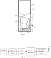
- an exit at the bottom of a water butt (2) is connected to the bottom of a rainfall measuring tube (13) via a water hose (14).
- a siphon (5) is in the wall of the rainfall measuring tube (13).
- the rainfall measuring tube (13) and a measuring device (6) are installed on a support bracket (9).
- the measuring device (6) is connected with a pressure sensor (12) which is installed in the bottom of the rainfall measuring tube (13) through a signal transmission lines (8), and it is also connected with a battery (11) through a power line (10).
- the whole apparatus is installed in an outer barrel (1).
- the water butt (2) is fixed on a support ring (3) and the support ring is in the outer barrel (1).
- the measuring device (6) is connected to an antenna (7).
- the measuring device (6) described includes a amplification and filtering circuit, an A/D conversion circuit, a single-chip microcomputer and a remote transmission module GSM or GPRS.
- One terminal of the amplification and filtering circuit is connected with the pressure sensor (12), and the other terminal is connected with the remote transmission module GSM or GPRS via the A/D conversion circuit and the single-chip microcomputer.
- the amplification and filtering circuit described uses differential structure or integrated instrument amplifier to constitute the amplification and filtering circuit.
- the input signal is the output voltage signal of the pressure sensor which is in proportional to the water level, and the output signal is the output voltage signal of the amplification and filtering circuit.
- the outermost portion of this apparatus is a protection barrel; the upper portion of the internal portion of the apparatus is a water butt (2), which collects natural rainfall.
- the rain flows through the water hose (14) into the rainfall measuring tube (13) below.
- the rainfall measuring tube (13) is a cylindrical hollow tube.
- the pressure sensor (12) can measure the water level of the rainfall measuring tube, while the water level is in proportion to the rainfall.
- the siphon phenomenon occurs, and the water inside the rainfall measuring tube (13) will be discharged through the siphon automatically.
- the measuring device will process the signal of the pressure sensor (12) by a series of steps, such as amplification, filtering, A/D conversion, value conversion, compensation calculations, encoding and remote transmission to realize the remote automatic rainfall measurement.
- the battery (11) is the power of the measuring device (6) and pressure sensor (12). Because of using the automatic drainage realized by siphon principle and rainfall measurement realized by pressure measurement, the power consumption of the apparatus is very low, and it's possible to use a battery for long-term supply.
- the key feature of the measuring device (6) is the self-compensation algorithm described later, which makes the precision of the device much higher than the existing tipping-bucket rain recorder and siphon rainfall recorder.
- the component of the measuring device is shown in FIG. 2 .
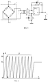
- the amplification and filtering circuit in FIG. 2 is an integrated operational amplifier of low power consumption, low temporal and thermal drift and low noise, which takes use of differential line structure.
- the circuit is shown in FIG. 3 . It can also use a variety of integrated instrument amplifier modules to constitute the amplification and filtering circuit.
- u i is the input voltage signal of the amplification and filtering circuit, which is also the output voltage signal of the pressure sensor that is in proportion to the water level.
- u o is the output voltage signal of the amplification and filtering circuit.
- A/D conversion circuit can be implemented with almost any kind of successive comparing parallel A/D converter or ⁇ - ⁇ type serial A/D converter.
- the present invention uses a 16 bit ⁇ - ⁇ type serial A/D converter (MAX1415 or MAX7705).
- Single chip microcomputer can be any product available. Considering of the power consumption, the present invention selects MSP430F series of TI. Specific model: MSP 430F135, or MSP 430F149.
- Remote transmission module GSM or GPRS can use productions of U.S. SIMCOM, German Siemens, or Taiwan BenQ, and the present invention uses sim300c of SIMCOM or BENQ M23 of BenQ.
- the method of rainfall measurement according to the present invention is as follows.
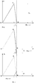
- FIG. 4-1 reflects the variation process of the water level of the rainfall measuring tube with rainfall.
- Segment O ⁇ A reflects the water level of the rainfall measuring tube rising by the rain.
- h N When the water level of the measuring tube reaches h N , siphon phenomenon occurs, and then the water level of the measuring tube falls.
- Segment A-B reflects this, and this process relies on siphon principle.
- point B In the cycle of water level of the rainfall measuring tube rising and falling, point B is the point O of the next cycle of water level, and the water level starts rising from the point B.
- FIG. 4-1 shows the variation process of the water level of the measuring tube with rainfall, and it is broken down into FIG. 4-2 and FIG. 4-3.
- FIG. 4-2 shows the variation process of the water level of the measuring tube without rainfall.
- FIG. 4-3 shows the changing of the water level caused by rainfall.
- Dotted line O-A-B in FIG. 4-2 and FIG. 4-3 is the actual changing curve of the water level shown in FIG. 4-1 .
- the actual changing curve of the water level without rainfall shown in FIG. 4-2 is the full line in t 1 ⁇ t ⁇ t' 2 .
- the chain line in t' 2 ⁇ t ⁇ t 2 is the extended line of the full line in t 1 ⁇ t ⁇ t' 2 .
- the chain line in t' 2 ⁇ t ⁇ t 2 will not exist in the siphon process without rainfall.
- the full line in t 1 ⁇ t ⁇ t' 2 and the chain line in t' 2 ⁇ t ⁇ t 2 are obtained by the subtraction between the curve of FIG. 4-1 and the curve of FIG. 4-3 . It can be drawn from FIG. 4-1, FIG. 4-2 and FIG. 4-3 that the falling rate of water level in the siphon process with rainfall (As shown in FIG. 4-1 , segment A-B) is slower than the rate without rainfall (As shown in FIG.
- h ( t ) represents the actual curve of the changing water level of the measuring tube with rainfall
- h 1 ( t ) represents the segment of the changing water level in the siphon process without rainfall and its extended line ( h 1 ( t ) include the full line and the chain line)
- h 2 ( t ) represents the changing of the water level caused by rainfall in t 1 ⁇ t ⁇ t 2 when siphon phenomenon occurs.
- h(t) in formula (1) is measured by the measuring system shown in FIG. 1 .
- the full line part of h 1 ( t ) is measured by the calibration test after the siphon and measuring tube are made and extended according to the slope of itself.
- the length of extended line is determined by t 2
- t 2 is determined by the rainfall rate.
- t 2 is big when the rainfall rate is big.
- t 2 is small when the rainfall rate is small.
- the time of every cycle of single measurement is unequal usually.
- h N is the maximum value of h(t), and the value of h N is determined by the structure of siphon and measuring tube.
- h N is a constant value in every single measurement.
- the actual curve of h ( t ) is not necessarily a straight line (usually a broken line), and h 2 ( t ) is not necessarily the translation of segment O-A of h ( t ).
- ⁇ h N ( j ) in formula (2) is the rainfall in t 1 ⁇ t ⁇ t 2 , i.e., in the siphon drainage process during a cycle of the j +1 th change of the water level of the measuring tube, and the cycle is showed in FIG. 4-1 .
- ⁇ h N equals to ⁇ h N ( j ), FIG. 4-3 .
- n means the loop showed in FIG.
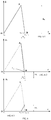
- the corresponding graphical representation of formula (3) is shown in FIG. 6 .
- the single cycle expressed by FIG. 6-1 is the same as the single cycle expressed by FIG. 4-1 .
- (t 20 , t 11 and t 21 in FIG. 6-1 are corresponding with 0, t 1 and t 2 in FIG. 4-1 Separately).
- h(t) in formula (3) is measured actually.
- h 1 ( t ) in t 1 (n+1) ⁇ t ⁇ t' 2(n+1) is the inherent siphon drainage line that has been predetermined
- h 1 ( t ) is an extended line of the inherent siphon drainage line.
- t 2(n+1) can be determined by the moment when the cycle reaches its bottom in FIG. 6-1 , and this can be realized by the corresponding programs at MCU in the measuring device.
Landscapes
- Life Sciences & Earth Sciences (AREA)
- Environmental & Geological Engineering (AREA)
- Hydrology & Water Resources (AREA)
- Engineering & Computer Science (AREA)
- Atmospheric Sciences (AREA)
- Biodiversity & Conservation Biology (AREA)
- Ecology (AREA)
- Environmental Sciences (AREA)
- Measurement Of Levels Of Liquids Or Fluent Solid Materials (AREA)
Claims (4)
- Procédé de mesure à distance des précipitations de type drainage par siphon à auto-compensation, caractérisé en ce qu'il comprend :
l'expression de la quantité de précipitations à tout moment par auto-compensation en tant que : h N est un niveau d'eau au niveau duquel un phénomène de siphon se produit ;Δh N (j) dans la formule (1) est la quantité de précipitations dans t 1(n+1) ≤ t≤t 2(n+1)), c'est-à-dire dans le processus de drainage par siphon pendant un cycle du j+1 ième changement d'un niveau d'eau d'un tube de mesure ;chaque Δh N (j) est généralement différent, c'est-à-dire Δh N (j-1) ≠ Δh N (j) ≠ Δh N (j+1) et si i<0, alors Δh N (i) =0 ;n est un nombre entier ≥0 qui indique que la boucle du changement du niveau d'eau du tube de mesure a exécuté n cycles ;K est un facteur d'échelle permettant de convertir le niveau d'eau du tube de mesure en la quantité de précipitations ;h S(n+1) (t) est exprimé en tant que :
 h(t) est un niveau d'eau réel mesuré par le tube de mesure ;h 1(t) dans (t 1(n+1)≤t≤t' 2(n+1) est une ligne de drainage par siphon inhérente, qui est un rapport connu ayant été prédéterminé,h 1(t) dans t'2(n+1)≤t≤t 2(n+1) est une ligne étendue de la ligne de drainage par siphon inhérente ;t 2(n+1) est déterminé par le moment où le cycle du niveau d'eau du tube de mesure montant et descendant par drainage par siphon atteint son niveau le plus bas, et ceci est réalisé par des programmes correspondants au niveau d'un micro-ordinateur à puce unique MCU dans un dispositif de mesure ; après l'obtention t 2(n+1), les programmes du MCU formeront la ligne étendue de la ligne de drainage par siphon inhérente, et ensuite h 1(t) sera déterminé totalement dans t 1(n+1)≤t≤t 2(n+1) ;le remplacement du résultat de la formule (2) par rapport à la formule (1) pour obtenir la valeur mesurée de la quantité de précipitations avec la compensation h pluie (t),
dans lequel ΔhN est le changement du niveau d'eau du tube de mesure pendant le processus de siphon réel avec les précipitations, moins le changement du niveau d'eau dans le processus de siphon sans les précipitations et leur ligne étendue, étendue jusqu'au point temporel (B) où le processus de siphon réel avec précipitations est exécuté. - Appareil permettant de mettre en œuvre le procédé selon la revendication 1, caractérisé en ce que :une sortie au niveau de la partie inférieure d'un réservoir d'eau (2) est reliée à la partie inférieure d'un tube de mesure de précipitations (13) par l'intermédiaire d'un tuyau d'eau (14) ;un siphon (5) se trouve dans la paroi du tube de mesure des précipitations (13) ;le tube de mesure des précipitations (13) et le dispositif de mesure (6) sont installés sur une console de support (9) ;le dispositif de mesure (6) comprend le micro-ordinateur à puce unique ;le dispositif de mesure (6) est relié à un capteur de pression (12) installé dans la partie inférieure du tube de mesure de précipitations (13) et à une batterie (11) ; etla totalité de l'appareil est installée dans un cylindre externe (1).
- Appareil selon la revendication 2, caractérisé en ce que le dispositif de mesure (6) comprend en outre un circuit d'amplification et de filtrage, un circuit de conversion A/N et un module de transmission à distance GSM ou GPRS ; un terminal du circuit d'amplification et de filtrage est relié au capteur de pression (12), et l'autre terminal est relié au module de transmission à distance GSM ou GPRS par l'intermédiaire du circuit de conversion A/N et du micro-ordinateur à puce unique.
- Appareil selon la revendication 2, caractérisé en ce que le circuit d'amplification et de filtrage utilise une structure différentielle d'un amplificateur d'instrument intégré pour constituer le circuit d'amplification et de filtrage, et un signal d'entrée est un signal de tension de sortie du capteur de pression qui est proportionnel au niveau d'eau, et le signal de sortie est le signal de tension de sortie du circuit d'amplification et de filtrage.
Applications Claiming Priority (2)
| Application Number | Priority Date | Filing Date | Title |
|---|---|---|---|
| CN2009101541691A CN101718881B (zh) | 2009-11-09 | 2009-11-09 | 具有自补偿功能的远程虹吸排水式降雨量测量方法和装置 |
| PCT/CN2010/076190 WO2011054235A1 (fr) | 2009-11-09 | 2010-08-20 | Dispositif et procédé de mesure à distance de la hauteur des précipitations par drainage par siphon à fonction d'auto-compensation |
Publications (3)
| Publication Number | Publication Date |
|---|---|
| EP2500751A1 EP2500751A1 (fr) | 2012-09-19 |
| EP2500751A4 EP2500751A4 (fr) | 2017-05-17 |
| EP2500751B1 true EP2500751B1 (fr) | 2019-12-04 |
Family
ID=42433483
Family Applications (1)
| Application Number | Title | Priority Date | Filing Date |
|---|---|---|---|
| EP10827849.0A Active EP2500751B1 (fr) | 2009-11-09 | 2010-08-20 | Dispositif et procédé de mesure à distance de la hauteur des précipitations par drainage par siphon à fonction d'auto-compensation |
Country Status (4)
| Country | Link |
|---|---|
| US (1) | US9588253B2 (fr) |
| EP (1) | EP2500751B1 (fr) |
| CN (1) | CN101718881B (fr) |
| WO (1) | WO2011054235A1 (fr) |
Families Citing this family (14)
| Publication number | Priority date | Publication date | Assignee | Title |
|---|---|---|---|---|
| CN101718881B (zh) * | 2009-11-09 | 2011-01-05 | 中国计量学院 | 具有自补偿功能的远程虹吸排水式降雨量测量方法和装置 |
| ES2436693B1 (es) * | 2012-06-29 | 2014-08-22 | Geonica, S.A. | Pluviómetro con sifón de cebado automático |
| CN102866437B (zh) * | 2012-10-23 | 2014-07-09 | 东北林业大学 | 一种盛雨器水量快速测量方法 |
| CN103362202A (zh) * | 2013-07-12 | 2013-10-23 | 浙江海河环境科技有限公司 | 初期雨水收集自动切换系统 |
| CN103675952A (zh) * | 2013-12-08 | 2014-03-26 | 无锡蚂蚁微威科技有限公司 | 曲颈降雨测量器 |
| CN104729883A (zh) * | 2015-03-17 | 2015-06-24 | 周庆华 | 径流泥沙自动监测仪进水口虹吸式调节装置 |
| CN104748820A (zh) * | 2015-03-17 | 2015-07-01 | 周庆华 | 泥水自动称重仪 |
| CN105068156A (zh) * | 2015-09-15 | 2015-11-18 | 成都汉康信息产业有限公司 | 用于地质灾害的雨量检测仪 |
| CN106197546A (zh) * | 2016-07-29 | 2016-12-07 | 南京工业职业技术学院 | 一种自动检测和播报的雨水监控装置 |
| CN109459804B (zh) * | 2018-11-26 | 2023-08-15 | 南京信息工程大学 | 一种雨量计 |
| CN109343156B (zh) * | 2018-12-10 | 2020-12-15 | 安徽沃特水务科技有限公司 | 一种防雨量漏报的遥测终端机 |
| CN109444993B (zh) * | 2018-12-10 | 2023-08-22 | 南京信息工程大学 | 一种基于msp单片机的超声波雨量计及雨量测量方法 |
| CN114488353B (zh) * | 2022-01-05 | 2026-04-14 | 广州极飞科技股份有限公司 | 降雨量测量方法及装置、存储介质及电子设备 |
| CN114442201A (zh) * | 2022-01-24 | 2022-05-06 | 张锦霞 | 一种智能测量降雨量的雨量计 |
Family Cites Families (18)
| Publication number | Priority date | Publication date | Assignee | Title |
|---|---|---|---|---|
| CN87210894U (zh) * | 1987-07-22 | 1988-04-06 | 云南省西双版纳州水文站 | 虹吸式月记雨量计 |
| US4836018A (en) * | 1988-10-17 | 1989-06-06 | Charles Dispenza | Rain gauge with improved syphon discharge |
| FR2663129B1 (fr) * | 1990-06-12 | 1993-01-29 | Oneill Andre | Pluviometre a reservoir intermediaire. |
| FR2713784B1 (fr) * | 1993-12-13 | 1997-06-06 | Michel Haug | Pluviomètre à contacts et à vidange automatique. |
| US6027639A (en) * | 1996-04-30 | 2000-02-22 | Stormwater Treatment Llc | Self-cleaning siphon-actuated radial flow filter basket |
| US6649048B2 (en) * | 2001-11-20 | 2003-11-18 | Stormwater Management | Filter cartridge with regulated surface cleaning mechanism |
| CN2819241Y (zh) * | 2005-06-07 | 2006-09-20 | 河海大学 | 雨量计量控制器 |
| US8512555B1 (en) * | 2006-08-23 | 2013-08-20 | Contech Engineered Solutions LLC | Filter assembly, system and method |
| US8104499B2 (en) * | 2007-01-29 | 2012-01-31 | Abdul Rashid | Precision siphon operated septic field dosing system with filtration and backwash |
| DE102007004705A1 (de) * | 2007-01-31 | 2008-08-07 | Elsner Elektronik Gmbh | Niederschlagsmengenmessgerät |
| KR100872502B1 (ko) * | 2007-02-06 | 2008-12-10 | 대한민국 | 무게 및 배수 교차식 강수량계 |
| CN201021943Y (zh) * | 2007-02-12 | 2008-02-13 | 河海大学 | 一种虹吸校正数字雨量计 |
| US8110099B2 (en) * | 2007-05-09 | 2012-02-07 | Contech Stormwater Solutions Inc. | Stormwater filter assembly |
| CN100595607C (zh) * | 2007-05-16 | 2010-03-24 | 张敏 | 电子虹吸式雨量计 |
| CN201449459U (zh) * | 2009-06-23 | 2010-05-05 | 南京信息工程大学 | 一种雨量传感器 |
| CN101718881B (zh) * | 2009-11-09 | 2011-01-05 | 中国计量学院 | 具有自补偿功能的远程虹吸排水式降雨量测量方法和装置 |
| US8662328B2 (en) * | 2010-09-23 | 2014-03-04 | 9224-9838 Quebec Inc. | Interconnecting container system |
| US8820346B2 (en) * | 2012-02-23 | 2014-09-02 | Thomas L. CORBETT | Self-actuating drainage device and method of operation |
-
2009
- 2009-11-09 CN CN2009101541691A patent/CN101718881B/zh active Active
-
2010
- 2010-08-20 WO PCT/CN2010/076190 patent/WO2011054235A1/fr not_active Ceased
- 2010-08-20 EP EP10827849.0A patent/EP2500751B1/fr active Active
-
2012
- 2012-04-27 US US13/457,559 patent/US9588253B2/en active Active
Non-Patent Citations (1)
| Title |
|---|
| None * |
Also Published As
| Publication number | Publication date |
|---|---|
| US9588253B2 (en) | 2017-03-07 |
| CN101718881B (zh) | 2011-01-05 |
| EP2500751A4 (fr) | 2017-05-17 |
| US20120253675A1 (en) | 2012-10-04 |
| WO2011054235A1 (fr) | 2011-05-12 |
| CN101718881A (zh) | 2010-06-02 |
| EP2500751A1 (fr) | 2012-09-19 |
Similar Documents
| Publication | Publication Date | Title |
|---|---|---|
| US9588253B2 (en) | Method and apparatus for remote siphon drainage type rainfall measurement with self-compensation function | |
| CN101451903B (zh) | 一种半封闭单支连通管式桥梁挠度测试装置及方法 | |
| CN205175854U (zh) | 一种径流与泥沙的自动监测装置 | |
| US4965756A (en) | Method and apparatus for calibration of electronic gas meters | |
| CN203310718U (zh) | 一种测量机车燃油密度和液位高度的装置 | |
| CN101162165A (zh) | 基于电容传感器与标准文丘里管的低含气率气液两相流测量装置 | |
| CN101871266B (zh) | 混凝土冷却通水数据自动化采集系统 | |
| US4953386A (en) | Method and apparatus for proving electronic gas meters | |
| CN103345004B (zh) | 采用光纤光栅虹吸式雨量计的雨量监测网络及方法 | |
| CN103528791B (zh) | 坐底式全天候推移质泥沙实时监测仪及其测量方法 | |
| CN204613432U (zh) | 一种新型虹吸式雨量计装置 | |
| CN112067841A (zh) | 一种液位时差测量明渠流速的装置及方法 | |
| CN102435230A (zh) | 三角堰坡面小区径流流量测量系统 | |
| RU176710U1 (ru) | Устройство для измерения физических параметров в скважине | |
| CN111173496A (zh) | 一种油井产液量计量装置及方法 | |
| CN113945999A (zh) | 一种光学雨量传感器模拟检测装置及计量方法 | |
| CN108387277A (zh) | 灌区一体化水位流量无线测量方法及装置 | |
| CN108332712A (zh) | 压差式剖面沉降计及剖面沉降监测方法 | |
| CN101586979B (zh) | 一种恒流气泡式自动水位测量方法 | |
| CN101586981A (zh) | 一种微功耗恒流气泡式水位自动测量装置 | |
| US4926678A (en) | Method and apparatus for proving electronic gas meters at low flow rates | |
| CN205785187U (zh) | 一种垂直变形检测装置 | |
| CN105259209B (zh) | 一种lng蒸发速率的测量系统及计算方法 | |
| CN203364917U (zh) | 一种高精度的水位计和渗压计 | |
| CN100432705C (zh) | 液滴法电容式雨量计量方法及装置 |
Legal Events
| Date | Code | Title | Description |
|---|---|---|---|
| PUAI | Public reference made under article 153(3) epc to a published international application that has entered the european phase |
Free format text: ORIGINAL CODE: 0009012 |
|
| 17P | Request for examination filed |
Effective date: 20120425 |
|
| AK | Designated contracting states |
Kind code of ref document: A1 Designated state(s): AL AT BE BG CH CY CZ DE DK EE ES FI FR GB GR HR HU IE IS IT LI LT LU LV MC MK MT NL NO PL PT RO SE SI SK SM TR |
|
| DAX | Request for extension of the european patent (deleted) | ||
| RA4 | Supplementary search report drawn up and despatched (corrected) |
Effective date: 20170418 |
|
| RIC1 | Information provided on ipc code assigned before grant |
Ipc: G01W 1/14 20060101AFI20170410BHEP |
|
| STAA | Information on the status of an ep patent application or granted ep patent |
Free format text: STATUS: EXAMINATION IS IN PROGRESS |
|
| 17Q | First examination report despatched |
Effective date: 20180423 |
|
| GRAP | Despatch of communication of intention to grant a patent |
Free format text: ORIGINAL CODE: EPIDOSNIGR1 |
|
| STAA | Information on the status of an ep patent application or granted ep patent |
Free format text: STATUS: GRANT OF PATENT IS INTENDED |
|
| INTG | Intention to grant announced |
Effective date: 20190710 |
|
| GRAS | Grant fee paid |
Free format text: ORIGINAL CODE: EPIDOSNIGR3 |
|
| GRAA | (expected) grant |
Free format text: ORIGINAL CODE: 0009210 |
|
| STAA | Information on the status of an ep patent application or granted ep patent |
Free format text: STATUS: THE PATENT HAS BEEN GRANTED |
|
| AK | Designated contracting states |
Kind code of ref document: B1 Designated state(s): AL AT BE BG CH CY CZ DE DK EE ES FI FR GB GR HR HU IE IS IT LI LT LU LV MC MK MT NL NO PL PT RO SE SI SK SM TR |
|
| REG | Reference to a national code |
Ref country code: GB Ref legal event code: FG4D |
|
| REG | Reference to a national code |
Ref country code: CH Ref legal event code: EP |
|
| REG | Reference to a national code |
Ref country code: AT Ref legal event code: REF Ref document number: 1210087 Country of ref document: AT Kind code of ref document: T Effective date: 20191215 |
|
| REG | Reference to a national code |
Ref country code: DE Ref legal event code: R096 Ref document number: 602010062281 Country of ref document: DE |
|
| REG | Reference to a national code |
Ref country code: IE Ref legal event code: FG4D |
|
| REG | Reference to a national code |
Ref country code: NL Ref legal event code: MP Effective date: 20191204 |
|
| REG | Reference to a national code |
Ref country code: LT Ref legal event code: MG4D |
|
| PG25 | Lapsed in a contracting state [announced via postgrant information from national office to epo] |
Ref country code: GR Free format text: LAPSE BECAUSE OF FAILURE TO SUBMIT A TRANSLATION OF THE DESCRIPTION OR TO PAY THE FEE WITHIN THE PRESCRIBED TIME-LIMIT Effective date: 20200305 Ref country code: NO Free format text: LAPSE BECAUSE OF FAILURE TO SUBMIT A TRANSLATION OF THE DESCRIPTION OR TO PAY THE FEE WITHIN THE PRESCRIBED TIME-LIMIT Effective date: 20200304 Ref country code: LV Free format text: LAPSE BECAUSE OF FAILURE TO SUBMIT A TRANSLATION OF THE DESCRIPTION OR TO PAY THE FEE WITHIN THE PRESCRIBED TIME-LIMIT Effective date: 20191204 Ref country code: SE Free format text: LAPSE BECAUSE OF FAILURE TO SUBMIT A TRANSLATION OF THE DESCRIPTION OR TO PAY THE FEE WITHIN THE PRESCRIBED TIME-LIMIT Effective date: 20191204 Ref country code: FI Free format text: LAPSE BECAUSE OF FAILURE TO SUBMIT A TRANSLATION OF THE DESCRIPTION OR TO PAY THE FEE WITHIN THE PRESCRIBED TIME-LIMIT Effective date: 20191204 Ref country code: BG Free format text: LAPSE BECAUSE OF FAILURE TO SUBMIT A TRANSLATION OF THE DESCRIPTION OR TO PAY THE FEE WITHIN THE PRESCRIBED TIME-LIMIT Effective date: 20200304 Ref country code: ES Free format text: LAPSE BECAUSE OF FAILURE TO SUBMIT A TRANSLATION OF THE DESCRIPTION OR TO PAY THE FEE WITHIN THE PRESCRIBED TIME-LIMIT Effective date: 20191204 Ref country code: LT Free format text: LAPSE BECAUSE OF FAILURE TO SUBMIT A TRANSLATION OF THE DESCRIPTION OR TO PAY THE FEE WITHIN THE PRESCRIBED TIME-LIMIT Effective date: 20191204 |
|
| PG25 | Lapsed in a contracting state [announced via postgrant information from national office to epo] |
Ref country code: HR Free format text: LAPSE BECAUSE OF FAILURE TO SUBMIT A TRANSLATION OF THE DESCRIPTION OR TO PAY THE FEE WITHIN THE PRESCRIBED TIME-LIMIT Effective date: 20191204 |
|
| PG25 | Lapsed in a contracting state [announced via postgrant information from national office to epo] |
Ref country code: AL Free format text: LAPSE BECAUSE OF FAILURE TO SUBMIT A TRANSLATION OF THE DESCRIPTION OR TO PAY THE FEE WITHIN THE PRESCRIBED TIME-LIMIT Effective date: 20191204 |
|
| PG25 | Lapsed in a contracting state [announced via postgrant information from national office to epo] |
Ref country code: PT Free format text: LAPSE BECAUSE OF FAILURE TO SUBMIT A TRANSLATION OF THE DESCRIPTION OR TO PAY THE FEE WITHIN THE PRESCRIBED TIME-LIMIT Effective date: 20200429 Ref country code: CZ Free format text: LAPSE BECAUSE OF FAILURE TO SUBMIT A TRANSLATION OF THE DESCRIPTION OR TO PAY THE FEE WITHIN THE PRESCRIBED TIME-LIMIT Effective date: 20191204 Ref country code: NL Free format text: LAPSE BECAUSE OF FAILURE TO SUBMIT A TRANSLATION OF THE DESCRIPTION OR TO PAY THE FEE WITHIN THE PRESCRIBED TIME-LIMIT Effective date: 20191204 Ref country code: RO Free format text: LAPSE BECAUSE OF FAILURE TO SUBMIT A TRANSLATION OF THE DESCRIPTION OR TO PAY THE FEE WITHIN THE PRESCRIBED TIME-LIMIT Effective date: 20191204 Ref country code: EE Free format text: LAPSE BECAUSE OF FAILURE TO SUBMIT A TRANSLATION OF THE DESCRIPTION OR TO PAY THE FEE WITHIN THE PRESCRIBED TIME-LIMIT Effective date: 20191204 |
|
| PG25 | Lapsed in a contracting state [announced via postgrant information from national office to epo] |
Ref country code: SM Free format text: LAPSE BECAUSE OF FAILURE TO SUBMIT A TRANSLATION OF THE DESCRIPTION OR TO PAY THE FEE WITHIN THE PRESCRIBED TIME-LIMIT Effective date: 20191204 Ref country code: SK Free format text: LAPSE BECAUSE OF FAILURE TO SUBMIT A TRANSLATION OF THE DESCRIPTION OR TO PAY THE FEE WITHIN THE PRESCRIBED TIME-LIMIT Effective date: 20191204 Ref country code: IS Free format text: LAPSE BECAUSE OF FAILURE TO SUBMIT A TRANSLATION OF THE DESCRIPTION OR TO PAY THE FEE WITHIN THE PRESCRIBED TIME-LIMIT Effective date: 20200404 |
|
| REG | Reference to a national code |
Ref country code: DE Ref legal event code: R097 Ref document number: 602010062281 Country of ref document: DE |
|
| REG | Reference to a national code |
Ref country code: AT Ref legal event code: MK05 Ref document number: 1210087 Country of ref document: AT Kind code of ref document: T Effective date: 20191204 |
|
| PLBE | No opposition filed within time limit |
Free format text: ORIGINAL CODE: 0009261 |
|
| STAA | Information on the status of an ep patent application or granted ep patent |
Free format text: STATUS: NO OPPOSITION FILED WITHIN TIME LIMIT |
|
| PG25 | Lapsed in a contracting state [announced via postgrant information from national office to epo] |
Ref country code: DK Free format text: LAPSE BECAUSE OF FAILURE TO SUBMIT A TRANSLATION OF THE DESCRIPTION OR TO PAY THE FEE WITHIN THE PRESCRIBED TIME-LIMIT Effective date: 20191204 |
|
| 26N | No opposition filed |
Effective date: 20200907 |
|
| PG25 | Lapsed in a contracting state [announced via postgrant information from national office to epo] |
Ref country code: AT Free format text: LAPSE BECAUSE OF FAILURE TO SUBMIT A TRANSLATION OF THE DESCRIPTION OR TO PAY THE FEE WITHIN THE PRESCRIBED TIME-LIMIT Effective date: 20191204 Ref country code: SI Free format text: LAPSE BECAUSE OF FAILURE TO SUBMIT A TRANSLATION OF THE DESCRIPTION OR TO PAY THE FEE WITHIN THE PRESCRIBED TIME-LIMIT Effective date: 20191204 Ref country code: PL Free format text: LAPSE BECAUSE OF FAILURE TO SUBMIT A TRANSLATION OF THE DESCRIPTION OR TO PAY THE FEE WITHIN THE PRESCRIBED TIME-LIMIT Effective date: 20191204 |
|
| PG25 | Lapsed in a contracting state [announced via postgrant information from national office to epo] |
Ref country code: IT Free format text: LAPSE BECAUSE OF FAILURE TO SUBMIT A TRANSLATION OF THE DESCRIPTION OR TO PAY THE FEE WITHIN THE PRESCRIBED TIME-LIMIT Effective date: 20191204 |
|
| PG25 | Lapsed in a contracting state [announced via postgrant information from national office to epo] |
Ref country code: MC Free format text: LAPSE BECAUSE OF FAILURE TO SUBMIT A TRANSLATION OF THE DESCRIPTION OR TO PAY THE FEE WITHIN THE PRESCRIBED TIME-LIMIT Effective date: 20191204 |
|
| REG | Reference to a national code |
Ref country code: CH Ref legal event code: PL |
|
| PG25 | Lapsed in a contracting state [announced via postgrant information from national office to epo] |
Ref country code: LU Free format text: LAPSE BECAUSE OF NON-PAYMENT OF DUE FEES Effective date: 20200820 Ref country code: LI Free format text: LAPSE BECAUSE OF NON-PAYMENT OF DUE FEES Effective date: 20200831 Ref country code: CH Free format text: LAPSE BECAUSE OF NON-PAYMENT OF DUE FEES Effective date: 20200831 |
|
| REG | Reference to a national code |
Ref country code: BE Ref legal event code: MM Effective date: 20200831 |
|
| PG25 | Lapsed in a contracting state [announced via postgrant information from national office to epo] |
Ref country code: IE Free format text: LAPSE BECAUSE OF NON-PAYMENT OF DUE FEES Effective date: 20200820 Ref country code: BE Free format text: LAPSE BECAUSE OF NON-PAYMENT OF DUE FEES Effective date: 20200831 |
|
| PG25 | Lapsed in a contracting state [announced via postgrant information from national office to epo] |
Ref country code: TR Free format text: LAPSE BECAUSE OF FAILURE TO SUBMIT A TRANSLATION OF THE DESCRIPTION OR TO PAY THE FEE WITHIN THE PRESCRIBED TIME-LIMIT Effective date: 20191204 Ref country code: MT Free format text: LAPSE BECAUSE OF FAILURE TO SUBMIT A TRANSLATION OF THE DESCRIPTION OR TO PAY THE FEE WITHIN THE PRESCRIBED TIME-LIMIT Effective date: 20191204 Ref country code: CY Free format text: LAPSE BECAUSE OF FAILURE TO SUBMIT A TRANSLATION OF THE DESCRIPTION OR TO PAY THE FEE WITHIN THE PRESCRIBED TIME-LIMIT Effective date: 20191204 |
|
| PG25 | Lapsed in a contracting state [announced via postgrant information from national office to epo] |
Ref country code: MK Free format text: LAPSE BECAUSE OF FAILURE TO SUBMIT A TRANSLATION OF THE DESCRIPTION OR TO PAY THE FEE WITHIN THE PRESCRIBED TIME-LIMIT Effective date: 20191204 |
|
| PGFP | Annual fee paid to national office [announced via postgrant information from national office to epo] |
Ref country code: GB Payment date: 20220825 Year of fee payment: 13 Ref country code: DE Payment date: 20220824 Year of fee payment: 13 |
|
| PGFP | Annual fee paid to national office [announced via postgrant information from national office to epo] |
Ref country code: FR Payment date: 20220823 Year of fee payment: 13 |
|
| REG | Reference to a national code |
Ref country code: DE Ref legal event code: R119 Ref document number: 602010062281 Country of ref document: DE |
|
| GBPC | Gb: european patent ceased through non-payment of renewal fee |
Effective date: 20230820 |
|
| PG25 | Lapsed in a contracting state [announced via postgrant information from national office to epo] |
Ref country code: GB Free format text: LAPSE BECAUSE OF NON-PAYMENT OF DUE FEES Effective date: 20230820 |
|
| PG25 | Lapsed in a contracting state [announced via postgrant information from national office to epo] |
Ref country code: GB Free format text: LAPSE BECAUSE OF NON-PAYMENT OF DUE FEES Effective date: 20230820 Ref country code: FR Free format text: LAPSE BECAUSE OF NON-PAYMENT OF DUE FEES Effective date: 20230831 Ref country code: DE Free format text: LAPSE BECAUSE OF NON-PAYMENT OF DUE FEES Effective date: 20240301 |