EP2500754A1 - Dispositif d'éclairage pour véhicule automobile - Google Patents
Dispositif d'éclairage pour véhicule automobile Download PDFInfo
- Publication number
- EP2500754A1 EP2500754A1 EP12159388A EP12159388A EP2500754A1 EP 2500754 A1 EP2500754 A1 EP 2500754A1 EP 12159388 A EP12159388 A EP 12159388A EP 12159388 A EP12159388 A EP 12159388A EP 2500754 A1 EP2500754 A1 EP 2500754A1
- Authority
- EP
- European Patent Office
- Prior art keywords
- light
- light guide
- lighting device
- longitudinal side
- volume
- Prior art date
- Legal status (The legal status is an assumption and is not a legal conclusion. Google has not performed a legal analysis and makes no representation as to the accuracy of the status listed.)
- Granted
Links
Images




Classifications
-
- G—PHYSICS
- G02—OPTICS
- G02B—OPTICAL ELEMENTS, SYSTEMS OR APPARATUS
- G02B6/00—Light guides; Structural details of arrangements comprising light guides and other optical elements, e.g. couplings
- G02B6/0001—Light guides; Structural details of arrangements comprising light guides and other optical elements, e.g. couplings specially adapted for lighting devices or systems
- G02B6/0011—Light guides; Structural details of arrangements comprising light guides and other optical elements, e.g. couplings specially adapted for lighting devices or systems the light guides being planar or of plate-like form
- G02B6/0075—Arrangements of multiple light guides
- G02B6/0076—Stacked arrangements of multiple light guides of the same or different cross-sectional area
-
- F—MECHANICAL ENGINEERING; LIGHTING; HEATING; WEAPONS; BLASTING
- F21—LIGHTING
- F21S—NON-PORTABLE LIGHTING DEVICES; SYSTEMS THEREOF; VEHICLE LIGHTING DEVICES SPECIALLY ADAPTED FOR VEHICLE EXTERIORS
- F21S41/00—Illuminating devices specially adapted for vehicle exteriors, e.g. headlamps
- F21S41/10—Illuminating devices specially adapted for vehicle exteriors, e.g. headlamps characterised by the light source
- F21S41/14—Illuminating devices specially adapted for vehicle exteriors, e.g. headlamps characterised by the light source characterised by the type of light source
- F21S41/141—Light emitting diodes [LED]
-
- G—PHYSICS
- G02—OPTICS
- G02B—OPTICAL ELEMENTS, SYSTEMS OR APPARATUS
- G02B6/00—Light guides; Structural details of arrangements comprising light guides and other optical elements, e.g. couplings
- G02B6/0001—Light guides; Structural details of arrangements comprising light guides and other optical elements, e.g. couplings specially adapted for lighting devices or systems
- G02B6/0005—Light guides; Structural details of arrangements comprising light guides and other optical elements, e.g. couplings specially adapted for lighting devices or systems the light guides being of the fibre type
- G02B6/001—Light guides; Structural details of arrangements comprising light guides and other optical elements, e.g. couplings specially adapted for lighting devices or systems the light guides being of the fibre type the light being emitted along at least a portion of the lateral surface of the fibre
-
- G—PHYSICS
- G02—OPTICS
- G02B—OPTICAL ELEMENTS, SYSTEMS OR APPARATUS
- G02B6/00—Light guides; Structural details of arrangements comprising light guides and other optical elements, e.g. couplings
- G02B6/0001—Light guides; Structural details of arrangements comprising light guides and other optical elements, e.g. couplings specially adapted for lighting devices or systems
- G02B6/0011—Light guides; Structural details of arrangements comprising light guides and other optical elements, e.g. couplings specially adapted for lighting devices or systems the light guides being planar or of plate-like form
- G02B6/0013—Means for improving the coupling-in of light from the light source into the light guide
- G02B6/0023—Means for improving the coupling-in of light from the light source into the light guide provided by one optical element, or plurality thereof, placed between the light guide and the light source, or around the light source
- G02B6/0028—Light guide, e.g. taper
-
- G—PHYSICS
- G02—OPTICS
- G02B—OPTICAL ELEMENTS, SYSTEMS OR APPARATUS
- G02B6/00—Light guides; Structural details of arrangements comprising light guides and other optical elements, e.g. couplings
- G02B6/0001—Light guides; Structural details of arrangements comprising light guides and other optical elements, e.g. couplings specially adapted for lighting devices or systems
- G02B6/0011—Light guides; Structural details of arrangements comprising light guides and other optical elements, e.g. couplings specially adapted for lighting devices or systems the light guides being planar or of plate-like form
- G02B6/0033—Means for improving the coupling-out of light from the light guide
- G02B6/0035—Means for improving the coupling-out of light from the light guide provided on the surface of the light guide or in the bulk of it
- G02B6/0036—2-D arrangement of prisms, protrusions, indentations or roughened surfaces
Definitions
- the present invention relates to a lighting device for a motor vehicle according to the preamble of claim 1.
- a lighting device has a first light guide and a second light guide, which is designed following the shape of the first light guide and adjacent to the first light guide.
- Such a lighting device is assumed to be known by the inventors. From the DE 10 2008 048 765 A1 a lighting device is known which has a flat light guide with two elongated narrow sides and two short narrow sides. The surface may have a curved shape in space. One of the long narrow sides is shaped so that it has a plurality of parabolic coupling areas. Each of the coupling-in areas is fed by an associated light-emitting diode (LED).
- the light-emitting diodes are on a flexible Printed circuit board, which is held by a holder in a predetermined three-dimensional shape.
- the coupled via the one elongated narrow side light is coupled out via the other elongated narrow side. This results for a viewer the appearance of a few millimeters, for example, 10 mm wide, three-dimensional curved in space light band.
- both white and yellow light are radiated, so that the prior art assumed prior art combines flashing light functions and daytime running light functions.
- the perceptible brightness when viewing the light bands varies over the length of the light bands. This is because, as it were, looking through the light guide at a series of LEDs. The areas of the light guides in front of the LEDs appear bright and are interrupted by dark intermediate areas. In the known prior art, the appearance homogeneity can only be improved by increasing the number of LEDs used.
- the object of the invention is to specify a lighting device that does not have these disadvantages or at least only in a reduced form.
- the invention is characterized in that the first optical waveguide has a first longitudinal side with first coupling-out elements which protrude from the first longitudinal side and have the first light-emitting surfaces, the second optical waveguide has a second longitudinal side with second outcoupling elements which protrude from the second longitudinal side and have second light exit surfaces, and in that the two optical waveguides are arranged relative to one another such that the second longitudinal side lies opposite the first longitudinal side.
- the function of the LEDs used in the known state of the prior art to emit light at a certain point in space is replaced in the invention by the light-emitting function of the decoupling elements.
- the decoupling replace insofar the LEDs.
- Each decoupling element can be regarded as a virtual light source.
- light is guided to the virtual light sources, while in the prior art assumed prior art electrical energy must be transported to the LEDs. With regard to the energy distribution, the light guide takes over Invention thus the function of the flexible printed circuit board of the prior art assumed prior art.
- the height of the decoupling determines the width of the resulting light band.
- this height is freely selectable independently of the other dimensions of the light guide and can be lowered to values of less than 3 mm, for example, so that a correspondingly narrow width of the light band results.
- the minimum surface area required by law of the illuminating surface is 2500 mm 2 .
- the width of the light band For a given length of the light band, there are thus restrictions on the width of the light band. For example, given a length of 400 mm, the width must be at least 6.25 mm on average.
- a significant advantage of the invention is that the width of the light band can be selected by an appropriate choice of the height of the coupling elements regardless of required for the stability of the light guide assembly minimum thicknesses of the other light guide.
- two light emitting diodes can be mounted on a circuit board, each radiating into a light guide.
- This board can be provided with recordings or mounting options for the light guide. This has the advantage that the light guide can be easily aligned to the light emitting diode.
- the lighting unit can be designed in this way be that light guides and boards form a separate assembly that is easy to mount in the headlight.
- the two light conductors required in the invention are simple injection-molded parts which, for example, can also have a substantially smaller volume of material than is the case with the known prior art. This leads to a massive weight saving, which is also advantageous from the point of view of a desired reduction in the CO 2 emissions of motor vehicles.
- the decoupling elements can be arranged more closely adjacent than LEDs.
- the decoupling elements can be arranged, for example, at a distance of less than 3 mm. When viewed from a distance of several meters, this distance from human vision is no longer resolved, so that the luminous light exit surfaces of the decoupling elements show the appearance of a continuously homogeneously illuminated band.
- photometric properties of the system can be combined in many ways.
- two different lighting tasks can be combined, or two light colors, light volumes or light distributions.
- these different properties can be combined in many ways.
- Examples of different lighting tasks are, for example, position light and daytime running light, both of which use white light.
- Examples of different light colors result for daytime running lights and flashing lights, with daytime running lights using white light and flashing light using yellow light.
- the light volume can be changed, for example, by activating either only one or both light guides by switching on their respective light source for light emission.
- two different light distributions can be realized, for example, if the one of the two light guides emits light preferably in a different direction than the other light guide.
- a preferred embodiment is characterized in that the first optical waveguide and the second optical waveguide are realized as partial volumes of an integrally connected optical waveguide volume.
- first subvolume has a first longitudinal side with outcoupling elements which protrude from the first longitudinal side
- second subvolume has a second longitudinal side with outcoupling elements which protrude from the second longitudinal side, wherein the decoupling elements of both subvolumes are identical to one another are.
- the illumination device is set up such that both the first subvolume and the second subvolume receive light both at a first end side, or at a first end, and at a second end side, or at a second end.
- LEDs are provided as light sources, each of which is arranged on a light entry surface, ie an end face, at one of the two ends of the subvolumes so that their light is coupled via the associated light entry surface in the light guide volume.
- the decoupling elements have two types of deflecting surfaces, one each type for each of the two light-coupling light sources having ends, wherein the one deflecting faces the one end, while the other deflecting faces the other end.
- the optical fiber volume is adapted to receive light coupled in only at one end of its two ends.
- the optical fiber volume has only one type of decoupling surfaces, which are all adapted to redirect light, which is fed into the optical fiber volume from one end of the optical fiber volume and enters the decoupling elements, to the light exit surfaces of the decoupling elements via which the Light emerges from the fiber optic volume.
- the individual light exit surfaces are separated by recesses.
- the illumination device has a first light source that emits white light and couples it into the first light guide and has a second light source that emits white light and couples it into the second light guide, and that the first light source and the second light source are arranged in this way are that their light in opposite directions propagated through the light guide.
- the illumination device is set up such that the light coupling into the two light guides can be varied so that in a first operating state light is coupled into only one of the two light guides, while in a second operating state light is coupled into both light guides.
- the two light sources separately switched on and off.
- a surface normal of a deflection surface of the decoupling element forms an angle bisector of the angle between a beam incident on the deflection surface and the reflected beam leading away from the deflection surface.
- the deflection surfaces are coated with a reflective coating.
- such a coating has a vapor-deposited metallic layer.
- the illumination device has at least one light guide, which has a light entrance surface and a light exit surface, wherein the light entry surface is arranged so that it is illuminated by light exit surfaces of the outcoupling elements of the first light guide and the second light guide.
- the light guide has a cross-section which widens in the propagation direction of the light propagating through the light guide.
- the cross section of the light guide is trapezoidal.
- the light entry surface of the optical attachment has a width which corresponds to the distance between the two light guides or only less than 15% greater than this distance.
- the light entry surface and / or the light exit surface of the light guide has scattering optics.
- the light-conducting optical fibers of the light module are arranged behind a bezel which forms an opening forming a window in front of the outcoupling elements located in the gap between the two light guides.
- Fig. 1 shows in detail a front view of a lighting device 10 for a motor vehicle with a housing 12.
- the in the FIG. 1 illustrated x-direction indicates a direction, for example, is parallel to a transverse axis of the motor vehicle.
- the y-direction is for example parallel to the vertical axis of the motor vehicle and the z-direction corresponds to the light emission direction.
- the illumination device 10 has a first light guide 14 and a second light guide 16, which designed following the shape of the first light guide and adjacent to the first light guide 14 is arranged to extend.
- the light guide 14, 16 each straight.
- the invention is not limited to such embodiments.
- the light guides 14, 16 are preferably curved in space to follow design guidelines in the design of the lights.
- the first light guide 14 is fed by a first light source 18, which is arranged in the illustrated embodiment on an end face of the first light guide 14.
- the second light guide 16 is fed by a second light source 20, which is arranged on an end face of the second light guide 16.
- the first light source 18 and the second light source 20 are preferably in each case a semiconductor light source, in particular a light-emitting diode or an arrangement of a plurality of light-emitting diodes.
- the light-emitting diode or the light-emitting diodes are for Example: LEDs with planar and square light emission surfaces of 1 mm edge length. Depending on which light function is to be fulfilled, white glowing, yellow glowing or red glowing LEDs are used.
- the first light guide 14 forms, together with the first light source 18, the second light guide 16 and the second light source 20, a light module 22, which is housed in a housing of a separate light or together with other light modules in a further light functions fulfilling light or a headlight.
- the housing may also be a body part, for example, the trim of an exterior mirror in a flashing light.
- the end faces of the light guides 14, 16 form, together with the longitudinal sides of the light guides 14, 16, the surface of the light guides 14, 16.
- the longitudinal sides of the light guides 14, 16 form a lateral surface.
- the first light guide 14 has a first longitudinal side 24 with first outcoupling elements 26.
- a longitudinal side a side of the light guide 14, 16 is understood, whose length is greater than a width and greater than a depth of the light guide 14, 16.
- the width of the light guide 14, 16 would be when in the FIG. 1 represented object of height in the y-direction, while the depth along the z-direction would be measured.
- the first outcoupling elements 26 protrude out of the first longitudinal side 24 and have first light exit surfaces 28.
- a decoupling element 26 preferably has a light exit surface 28 in each case.
- the second light guide 16 has a second longitudinal side 30 with second outcoupling elements 32.
- the second Decoupling elements 32 project out of the second longitudinal side 30 and have second light exit surfaces 34. Again, it is preferable that in each case a decoupling element 32 has a light exit surface 34.
- the first outcoupling elements 28 are arranged distributed over the first longitudinal side 24 of the first light guide 14.
- the first decoupling elements 28 are preferably in a row.
- the arrangement in a row preferably follows a guide line of the light guide.
- the imaginary line is understood to mean an imaginary line that lies in the interior of the light guide and that follows the outer shape of the light guide.
- the coupling-out elements of the one light guide are arranged in the immediate vicinity of the coupling-out elements of the other light guide.
- the second decoupling elements 32 are distributed over the second longitudinal side 30 of the second optical waveguide 16. Again, the second decoupling elements 32 preferably lie in a row.
- Both light guides are thus next to each other following the shape of the respective other light guide and can thereby have complex curvatures along their longitudinal direction or guide line, without this causing any loss in the quality of illumination.
- the two light guides 14 and 16 are largely hidden in the illustrated embodiment by a bezel 35, that only leaves a viewing window 37, in which the light exit surfaces 28 and 34 of the rows of outcoupling elements 26 and 32 are visible.
- a decoupling element of one of the two light guides 14, 16 in each case fits into a gap between two adjacent decoupling elements of the respective other optical waveguide 16, 14.
- This dimensioning of the dimensions of the decoupling elements and their distances allows the second longitudinal side 30 to be so close to the first longitudinal side 24 to arrange that the decoupling elements 26, which rise from the first longitudinal side 24 of the first light guide 14, with the decoupling elements 32, which rise from the second longitudinal side 30 of the second light guide 16, zipper-like interlock.
- the coupling of the light over the respective end face of the light guides 14, 16 takes place in such a way that the light propagates through the elongated shape of the respective light guide 14, 16 through the respective light guide 14, 16 and in particular runs along the rows of outcoupling elements 26, 32 ,
- the light propagating in the respective optical waveguide 14, 16 experiences internal total reflections on the walls of the respective optical waveguide 14, 16, wherein it changes its propagation direction according to the law of reflection. Due to its direction of propagation, part of the light propagating in the respective light guide 14, 16 passes into the outcoupling elements 26, 32 protruding from the respective longitudinal side 24, 30 and is coupled out via the associated light exit surfaces 28, 34. This will be explained in more detail below with reference to FIGS. 2 to 5 at a general example yet explained in more detail.
- the illumination device 10 is preferably a daytime running light, a separate flashing light, a raised brake light or another light that fulfills signal functions. It is also preferred that the illumination device 10 fulfills two light functions, for example by providing a daytime running light and a flashing light.
- the light module can also be integrated with headlamp light functions in a headlight.
- the lighting device according to the invention can be either a headlight or a lamp. Headlamps are used to illuminate the lane or unlit objects in the track, while lights have the function to make other road users on the motor vehicle or the behavior of the motor vehicle.
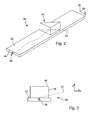
- the FIGS. 2 to 5 Specifically, they show a light guide 36, a light source 38, an outcoupling element 40 of the light guide 36 and a light beam 42.
- the light source 38 is preferably a semiconductor light source that emits light in a half space. It is preferably arranged close to a light entry surface 44 of the light guide 36, so that the majority of the light emitted by it is coupled into the volume of the light guide 36. In this embodiment, the light entry surface 44 is an end face of the light guide 36.
- the coupled light propagates there around a main propagation direction, which is predetermined by the geometry of the light guide 36.
- the main propagation direction corresponds to the x-direction since the elongated optical fiber 36 is along this x-direction is aligned.
- the propagation of light around the main propagation direction results from single or multiple total internal reflections of the light at interfaces of the light guide to lower refractive index media. With such total reflections, light incident on the interfaces out of the volume is reflected back into the volume.
- the rays involved in an image go through the given optical surfaces in a predetermined order. This also applies if several lenses and / or reflectors or mirrors are involved.
- the light guide presented here there are rays which pass directly from the coupling surface to the coupling-out element and there are rays which are reflected once or several times before they enter the coupling-out element.
- considered light beam 42 of the light source 38 enters via the light entrance surface 44 in the volume of the light guide 36 and has first directional components in the x-direction and y-direction.
- the in the FIG. 5 shown side view shows how the light beam 42 thereby remains bounded by total internal internal reflections 46, 48, 50, which serve as transport surfaces areas of long sides 52, 54 of the light guide 36 to the volume of the light guide 36 and in this volume to the main propagation x keeps running around. In this case, the light beam 42 reaches the decoupling element 40.
- FIGS. 2, 3 and 5 show the decoupling element 40 transversely to the main propagation direction x from a longitudinal side 52 of the photoconductive volume of the light guide 36 out.
- the decoupling element 40 is preferably a part of the optical waveguide 36, so that the volume of the optical waveguide 36 merges into the volume of the decoupling element 40, without an interface forming between these two volumes.
- light such as the light of the light beam 42, which impinges from the interior of the light-conducting volume on the base surface of the decoupling element 40, first passes through this base into the protruding from the longitudinal side 52 volume of the decoupling element 40 and no longer returns the rest of the optical fiber volume, so the volume of the light guide 36 without the decoupling element 40, back.
- the surfaces 56 and 58 serve essentially for deflecting the light bundle, for example in the direction of travel of the vehicle.
- the light distribution of the light may also involve a light guide, as described above with reference to the prior art.
- the decoupling element 40 has in the embodiment, which in the Fig. 2 to 5 is shown, a triangular, limited by lines base, in particular from the Figures 2 and 4 is apparent. In the illustrated embodiment is a right triangle, without the invention being limited to such a special geometry.
- the light which has entered the outcoupling element 40 via the triangular base area from the remaining light guide 36 is subsequently reflected by the boundary surface 56 which is located above the hypotenuse of the triangular base area, this reflection preferably being an internal total reflection. For such reflection, no reflective coating of the interface 56 is required.
- the interface 56 is coated with a reflective material.
- the reflective material is preferably a thin metal layer.
- the light incident on the boundary surface 56 from the volume of the light guide 36 is deflected there so that it falls at a steep angle onto a further boundary surface 58, which is aligned parallel to a longitudinal side 59 of the light guide 36 in the illustrated embodiment.
- a steep angle here means any angle between the incident light beam and the surface normal of the interface 58, which is smaller than the limiting angle of the total internal reflection. This means that the light incident on the further boundary surface 58 at steep angles experiences no internal total reflections there, but that it exits via the further interface 58 from the coupling-out element 40 and thus out of the light guide 36.
- the additional boundary surface 58 represents a light exit surface of the light guide 36.
- the boundary surface 56 represents an interference element which deflects incident light in such a way that the deflected light is coupled out on an interface of the light guide 36 on the next impact.
- the boundary surface 56 together with the further boundary surface 58, forms at least part of the interface of the decoupling element 40 FIGS. 2 to 5 illustrated embodiment is particularly characterized in that the decoupling element 40 protrudes from a longitudinal side 52 of the photoconductive volume of the light guide 36 and that the light exit surface 58 forms part of the interface of the decoupling element 40.
- the boundary surface 56 which serves as a disruptive element
- the further boundary surface 58 which serves as a light exit surface, lie on the same longitudinal side 52 of the light guide 36.
- the remaining interface 60 which in the FIG. 4 above a catheter of the base of the decoupling element 40 is, however, has no significance for the decoupling of the light propagating from the left.
- the base surface of the decoupling element 40 is located in the longitudinal side 52 of the light guide 36.
- the outer shape of the unit from the decoupling element 40 and the light guide 36 is effectively created by the fact that the shape of the decoupling element 40 is mentally placed on the longitudinal side 52 and thereby defines the base.
- this consideration serves only to illustrate the footprint.
- Real light guides are preferably produced as one-piece structural units from one or more outcoupling elements 40 with the remaining light-conducting volume of the light guide 36, in particular by an injection molding process with PMMA or PC as a transparent optical waveguide material.
- this lying in the longitudinal side 52 base surface should serve in the prior art as a light exit surface, would have a lying on the opposite longitudinal side surface 54 interference elements that would deflect the light steeply to the lying in the longitudinal side 52 base out.
- this surface area lying in the longitudinal side 54 could not serve, or only to a very limited extent, as a transport surface.
- the base surface lying in the longitudinal side 52 in the prior art would not only have to fulfill the function of a light exit surface, but additionally it would also have to serve as a transport surface.
- said surface area of the longitudinal side 54 remain free of interfering elements and thus serve as a transport surface.
- the outstanding in the invention from the longitudinal side 52 and serving as a light exit surface further interface 58 has no function as a transport surface to meet and can therefore be optimized for the deflection and bundling of the decoupled light.
- This spatial separation of the required light transport and light extraction interfaces of the light guide allows improved optimization of each of the interfaces with respect to their task of light transport or light extraction.
- Fig. 6 is a perspective view of the light module 22 of the Fig. 1 and illustrates in particular the decoupling of light 39 from the light exit surfaces 28 and 34 of the first light guide 14 and the second light guide 16.
- the emission of the light 39 takes place via the light exit surfaces 28, 34 of the coupled-out decoupling elements 26, 32 of the first light guide 14 and the second light guide 16.
- the observer therefore sees the light module 22 as a light band whose width corresponds approximately to the width of the gap between the first light guide 14 and the second light guide 16.
- the gap width can be reduced to very small values down to less than 3 mm.
- the light color can be varied by light different color emitting light sources 18, 20 used to couple light into the two light guides 14, 16.
- light sources emitting either red or yellow or white light in particular LEDs, it is thus possible to realize the combinations red-white, red-yellow, white-yellow, with red being used for tail light functions and brake light functions, white for daytime running light functions and position light functions and yellow for flashing light functions ,
- the known materials used for optical fibers such as PC (polycarbonate) and PMMA (polymethyl methacrylate) have the undesirable property of an absorption dependent on the wavelength of light. This results in a white light-operated light guide at distances from the location of the coupling of the light, which are greater than about 250 mm, to a color change in the direction of yellow. If white light is then coupled into one of the two light guides 14, 16 from the front and into the other light guide 16, 14 from the rear, the eye perceives at each point of the light band a superposition of the two respectively more yellowish white shades. In the viewer's perception, this results in a smaller change in color over the length of the light band than would be the case with a one-sided coupling of the light.
- a preferred embodiment therefore provides that the illumination device has a first light source which emits white light and couples it into the first light guide and has a second light source which emits white light and couples it into the second light guide, and in that the first light source 18 and second light source 20 are arranged so that their light in opposite directions through the Light guide 14, 16 propagated.
- the Fig. 6 shows an embodiment in which the first light source 18 and the second light source 20 at the same end 27 of the arrangement of the first light guide 14 and the second light guide 16 are arranged.
- the light propagates both light sources in the same direction through the light guide assembly, namely from a first end 27 to a second end 29 of the arrangement of the first light guide 14 and the second light guide 16.
- the first end 27 and the second end 29 are through an intermediate volume of the light guide 14 and / or the light guide 16 are separated from each other.
- one of the two light sources for example the first light source 18, at the first end 27 of the arrangement of the first light guide 14 and the second light guide 16 is preferred arranged, while the respective other light source, for example, the second light source 16, at the second end 29 of the arrangement of the first light guide 14 and the second light guide 16 is arranged.
- the coupling elements of the light guide in which the light is coupled from behind, must be aligned accordingly. From the FIGS. 2 to 5 This results in a certain orientation of the outgoing over a triangular base decoupling element.
- This orientation is characterized in that light entering the decoupling element is deflected at the hypotenuse side and decoupled via one of the catheter sides in the z-direction.
- the hypotenuse side is the front side facing, which is opposite to the front side, on which the light source 38 is arranged.
- the decoupling side of the catheter is oriented so that its surface normal points in the z-direction.
- the decoupling element must be arranged accordingly: Even then, that the Hypotenusenseite facing the end face, which faces the end face on which the light source 38 is arranged, and that for decoupling serving side of the catheter is oriented so that its surface normal points in the z-direction.
- the decoupling element can also have a different shape than the shape with the triangular base. It is essential that a side of the decoupling element serving as deflection surface redirects light which enters the decoupling element directly to the light exit surface of the decoupling element.
- a suitable embodiment is characterized in that the Auskoppetti a light guide are each reduced with increasing distance from the location of the light coupling in this light guide. As a result, a small amount of white light is emitted at a small distance from the location of the coupling and comparatively less yellow light is emitted at a greater distance. In the superposition with the light coupled out of the second light guide, this leads to the fact that the white light outshines the yellow light in each case.
- a preferred embodiment provides that the light coupling into the two light guides can be varied so that in a first operating state light is coupled into only one of the two light guides, while in a second operating state light is coupled into both light guides.
- This embodiment is preferably realized in that the two light sources, separately switched on and off.
- a source of light is literally understood to mean a source of light, irrespective of whether it is a single LED or a group of controllable LEDs or one or more other sources of light such as incandescent or gas discharge lamps, etc., acts.
- the light module therefore has at least separately activatable light sources. This implies at least separate lines as part of the light module, possibly also separately controllable switch, provided that they are integrated into the light module.
- the light sources which can be activated separately from one another are light emitting diodes which emit light of different colors.
- the yellow light source of a flashing light is assisted with the white light of a dimmed white light source.
- the flashing light function is particularly advantageous when a lamp with low
- the number of units can fulfill national regulations which can not be met by the light sources of one light function.
- cases are also conceivable in which a white light function is supported by yellow light sources.
- the invention is not limited to lighting devices with rectilinear optical fibers, but it can also be realized with three-dimensionally curved in space extending light guides.
- the axis about which the optical fiber is curved around lies in this case parallel to the light emission direction, that is, for example, parallel to a direction z.
- FIGS. 7 and 8th illustrate these relationships: One can think of a three-dimensionally curved light guide composed of short and straight pieces of light guide pieces.
- FIG. 7 shows three such optical fiber pieces 62, 64, 66 which are rotated about a parallel to the desired light emission z axis of rotation against each other.
- a curvature as represented by such a rotation, does not affect the light emission direction:
- the decoupling elements 40 of the optical waveguide pieces 62, 64, 66 are made identical to one another and are arranged identically to the rest of the respective optical waveguide element If the light guide piece 62 does not emit light in the direction z perpendicular to the paper plane, the light guide pieces 64 and 66 rotated relative to the light conductor piece 62 about a rotation axis parallel to the z direction emit their light in the same direction.
- FIG. 8 shows that this type of rotation, which represents a curvature of the light guide in the plane parallel to the carriage, can be compensated by changing the angle of attack of serving as Lichtumlenk Structure interface of the decoupling element.
- the compensating effect is achieved for a preferred embodiment in which the surface normal of the deflection surface 72 of the decoupling element 40 with the bisector of the angle between the incident on the deflection surface 72 beam 74 and the deflecting surface 72 leading away, reflected beam 76 forms.
- changes in the position of the deflection are narrow limits, since even after minor changes under certain circumstances no internal total reflections take place at the deflection.
- a preferred embodiment provides that the deflection surfaces 72 are coated with a reflective coating.
- Such a coating preferably has a vapor-deposited metallic layer.
- FIG. 9 shows a further embodiment, which is characterized in that the illumination device has at least one light guide 78, which has a light entrance surface 80 and a light exit surface 82, wherein the light entry surface 80 is arranged so that it from light exit surfaces 28, 34 of the decoupling elements 26, 32 of the first light guide 14 and the second light guide 16 is illuminated.
- This embodiment has the particular advantage that the very narrow light band, which is generated by the illumination device according to the invention, allows a very narrow light entry surface 80 of the light guide 78, without significant light losses occurring between the exit of the light from the outcoupling elements 26, 32 of the first light guide 14 and the second light guide 16 and the entry of the light into the light guide 78.
- the light guide 78 has a cross-section widening in the direction of propagation of the light propagating through the light guide 78, which is bounded by internally totally reflecting side walls 84, 86.
- the light emerging from the light exit surface 82 of the light guide 78 is aligned more parallel than the light entering the light guide 78. This parallelization arises as a result of the interaction of the widening cross section with the law of refraction.
- the cross section of the light guide 78 is trapezoidal. Due to the very narrow light entrance surface of the optical attachment whose width preferably corresponds to the distance between the two light guides or only slightly, in particular less than 15% greater than this distance, a comparatively large angle between the two non-parallel sides 84, 86 of the trapezoid can be selected can be without the optical fiber 78 is undesirably bulky and heavy. A large angle causes a greater parallelization than a smaller angle and is therefore desirable. This also applies analogously to deviating from the trapezoidal shape, widening cross sections of the attachment optics.
- the light entry surface 80 and / or the light exit surface 82 of the light guide 78 has scattering optics.
- Such Scattering optics which are realized as refractive interfaces of elevations or depressions on the surfaces mentioned, allow a desired influencing of the light distribution which is generated by the illumination device.
- the light-conducting light guides 14, 16 of the light module 22 are arranged behind a bezel 35 (cover frame, cover) which forms an opening forming a window 37 in front of the outcoupling elements 26 located in the gap between the two light guides 14, 16. 32 has.
- This has the advantage that one sees only a very slender part, while the massive volumes of the light guides 14, 16 of the illumination device 10 are obscured by the bezel 35.
- FIG. 1 illustrated zipper-like arrangement of both optical fibers with each other and of optical fibers to optical fibers of equal size decoupling limited. Further embodiments of arrangements and sizes of decoupling elements are in the FIGS. 10 to 15 shown.
- FIG. 10 shows an embodiment in which each form a coupling element of the first light guide 14 and a coupling element of the second light guide 16 form a pair of coupling elements.
- the decoupling elements of a pair are arranged side by side or one above the other.
- the decoupling of a light guide can be the same size or different sizes.
- the sizes and distances of the decoupling elements are such that within each pair of a pair of pairs each same arrangement of the decoupling element of a light guide to the Output coupling of the other light guide results.
- FIGS. 10 to 15 show embodiments in which the coupling elements of a light guide are each equal to each other.
- FIG. 11 shows an embodiment in which the outcoupling elements 26 of a light guide 14 are arranged offset to the outcoupling elements 34 of the other light guide 16. Unlike the subject of the FIG. 1 are the decoupling elements 26, 34 of both light guides 14, 16 but not interlocked. Incidentally, the decoupling elements of this embodiment are all the same size and, based on their light guide, arranged at the same distance from each other.
- FIG. 12 shows an embodiment in which the decoupling elements 26 of a light guide 14 differ in size from the outcoupling elements 34 of the other optical waveguide 16.
- the decoupling of a light guide are each equal to each other and arranged at the same distance from each other. The distances between the coupling-out elements of the one light guide differ from the distances between the coupling-out elements of the respective other light guide.
- FIG. 12 In addition, an embodiment in which the number of outcoupling elements of one light guide is different from the number of outcoupling elements of the respective other light guide and in which the outcoupling elements of a light guide differ in size from the outcoupling elements of the respective other light guide.
- FIG. 13 shows an embodiment in which the distance between outcoupling elements 26 of a light guide 14th is not constant from each other, while the decoupling elements 34 of the other optical fiber 16 have a constant distance from each other.
- FIG. 14 shows an embodiment in which the decoupling of the one light guide differ in size from the coupling elements of the other light guide.
- FIG. 15 shows an embodiment in which the sizes and shapes of the coupling elements of a light guide are the same, while the size and shape of a coupling element of the one light guide differs from the size and shape of the other light guide.
- FIG. 15 an embodiment in which the decoupling of the two light guides are arranged partially overlapping one behind the other.
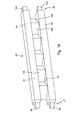
- FIG. 16 shows a preferred embodiment in which the first light guide and the second light guide are realized as partial volumes of an integrally connected light guide volume 88.
- FIG. 16 shows therefore a lighting device having a first optical fiber in the form of a first sub-volume 90 and a second optical fiber in the form of a second sub-volume 92, which is designed following the first shape of the first optical fiber and adjacent to the first optical fiber extending, wherein the first optical fiber a first longitudinal side 24 having first coupling elements 94, which protrude from the first longitudinal side 24 and have the first light exit surfaces, the second light guide has a second longitudinal side 30 with second outcoupling elements 94th which protrude from the second longitudinal side 30 and have second light exit surfaces, and wherein the two light guides are arranged relative to each other so that the second longitudinal side 30 of the first longitudinal side 24 is opposite.
- the decoupling elements 94 of both light guides are identical to each other in this one-piece design.
- the two sub-volumes 90, 92 each share their decoupling elements 94.
- Each decoupling element 94 has a side facing the first sub-volume 90, with which it merges into the first sub-volume 90 and a second sub-volume 92 side facing, with it in the second sub-volume 92 passes.
- the two sides are opposite each other and are separated by the intervening volume of the decoupling element 94.
- the design, in the FIG. 16 is shown, is adapted to that both the first sub-volume 90, and the second sub-volume 92 gets coupled both at a first end face, or at a first end 27, and at a second end face, or at a second end 29, light .
- four LEDs 96, 98, 100, 102 are preferably provided as light sources, each of which is arranged on a light entry surface, ie an end face, at one of the two ends 27, 29 of the subvolumes 90, 92 so that their light via the associated Light entrance surface is coupled into the light guide volume 88.
- the two light sources 96, 98 arranged at one end 27 are yellow-emitting LEDs in order to realize one flashing light module, while the other two light sources 100, 102 arranged at the other end 29 emit white light LEDs are, with which a daytime running light and / or position light light function is realized.
- a two-level brightness can be realized, as has already been explained above. The two-stage brightness is thus realized in that in a first stage light is coupled into only one of the two partial volumes 90, 92, while for a second, brighter stage, light is coupled into both partial volumes 90, 92.
- a pair of a white light emitting LED and a yellow light emitting LED is used at both ends 27, 29 respectively.
- the decoupling elements have in the embodiment that in the FIG. 16 is shown, two types of deflection surfaces 106, 108, depending on a type for each of the two light-emitting light sources having ends. Both types of deflection surfaces 106, 108 then reflect the light incident on them onto the same light exit surface. The one deflection surfaces 106 are facing one end 27, while the other deflection surfaces facing the other end 29.
- FIG. 17 shows a further embodiment of an integrally connected fiber optic volume 104. Also in this embodiment, the first optical fiber and the second optical fiber as partial volumes of the integrally connected fiber optic volume 104 are realized.
- FIG. 17a a side view of a longitudinal side of the optical fiber volume 104
- the Fig. 17b a plan view of the optical fiber volume 104
- the FIG. 17c a view of the light-coupling end 27 of the optical fiber volume 104
- the Fig. 17 d a perspective view of the optical fiber volume 104 with the viewer facing light exit surfaces
- the Fig. 17e a perspective view of the fiber optic volume 104 with the viewer facing deflection.
- FIG. 17 shows a lighting device having a first optical fiber in the form of a first sub-volume 90 and a second optical fiber in the form of a second sub-volume 92, which is designed following the first shape of the first optical fiber and adjacent to the first optical fiber extending, wherein the first optical fiber a first Longitudinal side 24 having first coupling elements 94 which protrude from the first longitudinal side 24 and have the first light exit surfaces, the second light guide having a second longitudinal side 30 with second coupling elements 94, which protrude from the second longitudinal side 30 and second light exit surfaces, and wherein the two Light guide are arranged relative to each other so that the second longitudinal side 30 of the first longitudinal side 24 is opposite.
- the decoupling elements 94 of both light guides are identical to each other in this one-piece design.
- the two sub-volumes 90, 92 each share their decoupling elements 94.
- Each decoupling element 94 has a side facing the first sub-volume 90, with which it merges into the first sub-volume 90 and a second sub-volume 92 side facing, with it in the second sub-volume 92 passes.
- the two sides are opposite each other and are separated by the intervening volume of the decoupling element 94.
- the fiber volume 104 after FIG. 17 arranged to be light coupled only at one end 27 of its two ends 27, 29 light.
- the individual light exit surfaces are at the subject of FIG. 17 separated by recesses 110. However, this represents only one possible embodiment. In an alternative embodiment, the light exit surfaces of the decoupling elements 94 merge into one another. Also for the subject of FIG. 17 It is true that both yellow and white and / or red light emitting LEDs can be used as light sources. Again, it is true that these light sources are each arranged so close to a light entry surface of a photoconductive subvolume of the light guide volume, that light emanating from them is coupled into the respective sub-volume.
- the following advantages result: For the light color, which is fed via two light entry surfaces in this embodiment, the result is a halving of the temperature load at the light entry surfaces. This is advantageous in order to avoid a thermal degradation of the optical fiber material, wherein the optical fiber material yellows with increasing value of the product of temperature and time. Another advantage arises especially for flashing light functions.
- the use of two LEDs helps to compensate for the low light output of widespread, yellow-emitting LEDs on the market.
Landscapes
- Physics & Mathematics (AREA)
- Optics & Photonics (AREA)
- General Physics & Mathematics (AREA)
- Engineering & Computer Science (AREA)
- Microelectronics & Electronic Packaging (AREA)
- General Engineering & Computer Science (AREA)
- Non-Portable Lighting Devices Or Systems Thereof (AREA)
Applications Claiming Priority (2)
| Application Number | Priority Date | Filing Date | Title |
|---|---|---|---|
| DE102011005583 | 2011-03-15 | ||
| DE102011078607A DE102011078607A1 (de) | 2011-03-15 | 2011-07-04 | Beleuchtungseinrichtung für Kraftfahrzeug |
Publications (2)
| Publication Number | Publication Date |
|---|---|
| EP2500754A1 true EP2500754A1 (fr) | 2012-09-19 |
| EP2500754B1 EP2500754B1 (fr) | 2016-03-09 |
Family
ID=45887938
Family Applications (1)
| Application Number | Title | Priority Date | Filing Date |
|---|---|---|---|
| EP12159388.3A Not-in-force EP2500754B1 (fr) | 2011-03-15 | 2012-03-14 | Dispositif d'éclairage pour véhicule automobile |
Country Status (2)
| Country | Link |
|---|---|
| EP (1) | EP2500754B1 (fr) |
| DE (1) | DE102011078607A1 (fr) |
Cited By (4)
| Publication number | Priority date | Publication date | Assignee | Title |
|---|---|---|---|---|
| EP2618045A1 (fr) * | 2012-01-20 | 2013-07-24 | Automotive Lighting Reutlingen GmbH | Dispositif dýéclairage pour un véhicule automobile |
| EP2851718A1 (fr) * | 2013-09-18 | 2015-03-25 | Automotive Lighting Reutlingen GmbH | Dispositif d'éclairage d'un véhicule automobile |
| US20180329128A1 (en) * | 2015-12-17 | 2018-11-15 | 3M Innovative Properties Company | Light guides |
| CN111828933A (zh) * | 2019-04-18 | 2020-10-27 | 法雷奥照明湖北技术中心有限公司 | 光传导件、发光模块和车辆 |
Families Citing this family (1)
| Publication number | Priority date | Publication date | Assignee | Title |
|---|---|---|---|---|
| DE102014206238A1 (de) | 2013-06-22 | 2014-12-24 | Volkswagen Aktiengesellschaft | Kraftfahrzeug mit einer Leuchtvorrichtung |
Citations (7)
| Publication number | Priority date | Publication date | Assignee | Title |
|---|---|---|---|---|
| US6575584B1 (en) * | 1999-05-28 | 2003-06-10 | Universite De Liege | Light guiding plate with internal micro-prisms |
| US20060209524A1 (en) * | 2005-03-17 | 2006-09-21 | Yoshiharu Tenmyo | Light-emitting device and apparatus having the same |
| EP2045633A1 (fr) * | 2007-10-04 | 2009-04-08 | Samsung Electronics Co., Ltd. | Plaque de guidage de lumière de type d`une seule piéce avec de protubérances prismatiques tranquées inversées et integrées et appareil de rétroéclairage l'utilisant |
| US20090185389A1 (en) * | 2008-01-18 | 2009-07-23 | Osram Sylvania Inc | Light guide for a lamp |
| DE102009012224A1 (de) * | 2009-03-07 | 2009-12-24 | Daimler Ag | Lichtleitvorrichtung und Fahrzeugbeleuchtungsvorrichtung |
| DE102008048765A1 (de) | 2008-09-24 | 2010-03-25 | Hella Kgaa Hueck & Co. | Beleuchtungsvorrichtung für Kraftfahrzeuge |
| US20100157624A1 (en) * | 2008-12-24 | 2010-06-24 | Coretronic Corporation | Light Guide Plate and Backlight Module |
-
2011
- 2011-07-04 DE DE102011078607A patent/DE102011078607A1/de not_active Withdrawn
-
2012
- 2012-03-14 EP EP12159388.3A patent/EP2500754B1/fr not_active Not-in-force
Patent Citations (7)
| Publication number | Priority date | Publication date | Assignee | Title |
|---|---|---|---|---|
| US6575584B1 (en) * | 1999-05-28 | 2003-06-10 | Universite De Liege | Light guiding plate with internal micro-prisms |
| US20060209524A1 (en) * | 2005-03-17 | 2006-09-21 | Yoshiharu Tenmyo | Light-emitting device and apparatus having the same |
| EP2045633A1 (fr) * | 2007-10-04 | 2009-04-08 | Samsung Electronics Co., Ltd. | Plaque de guidage de lumière de type d`une seule piéce avec de protubérances prismatiques tranquées inversées et integrées et appareil de rétroéclairage l'utilisant |
| US20090185389A1 (en) * | 2008-01-18 | 2009-07-23 | Osram Sylvania Inc | Light guide for a lamp |
| DE102008048765A1 (de) | 2008-09-24 | 2010-03-25 | Hella Kgaa Hueck & Co. | Beleuchtungsvorrichtung für Kraftfahrzeuge |
| US20100157624A1 (en) * | 2008-12-24 | 2010-06-24 | Coretronic Corporation | Light Guide Plate and Backlight Module |
| DE102009012224A1 (de) * | 2009-03-07 | 2009-12-24 | Daimler Ag | Lichtleitvorrichtung und Fahrzeugbeleuchtungsvorrichtung |
Cited By (7)
| Publication number | Priority date | Publication date | Assignee | Title |
|---|---|---|---|---|
| EP2618045A1 (fr) * | 2012-01-20 | 2013-07-24 | Automotive Lighting Reutlingen GmbH | Dispositif dýéclairage pour un véhicule automobile |
| EP2851718A1 (fr) * | 2013-09-18 | 2015-03-25 | Automotive Lighting Reutlingen GmbH | Dispositif d'éclairage d'un véhicule automobile |
| US9879836B2 (en) | 2013-09-18 | 2018-01-30 | Automotive Lighting Reutlingen Gmbh | Lighting device in a motor vehicle |
| US20180329128A1 (en) * | 2015-12-17 | 2018-11-15 | 3M Innovative Properties Company | Light guides |
| US10514487B2 (en) * | 2015-12-17 | 2019-12-24 | 3M Innovative Properties Company | Light guides |
| CN111828933A (zh) * | 2019-04-18 | 2020-10-27 | 法雷奥照明湖北技术中心有限公司 | 光传导件、发光模块和车辆 |
| CN111828933B (zh) * | 2019-04-18 | 2025-03-07 | 法雷奥照明湖北技术中心有限公司 | 光传导件、发光模块和车辆 |
Also Published As
| Publication number | Publication date |
|---|---|
| DE102011078607A1 (de) | 2012-09-20 |
| EP2500754B1 (fr) | 2016-03-09 |
Similar Documents
| Publication | Publication Date | Title |
|---|---|---|
| EP1854667B1 (fr) | Dispositif d'éclairage et rétroviseur extérieur avec un dispositif d'éclairage | |
| EP2338732B1 (fr) | Dispositif d'éclairage de véhicule automobile doté d'un guide de lumière et de sources lumineuses de différentes couleurs | |
| EP2784376B1 (fr) | Lampe de véhicule automobile pour fonctions d'éclairage dynamiques | |
| DE102012202508B4 (de) | Lichtleitervorrichtung für eine Kraftfahrzeugleuchte | |
| DE102008048765B4 (de) | Beleuchtungsvorrichtung für Kraftfahrzeuge | |
| DE102014205994B4 (de) | Lichtmodul mit Halbleiterlichtquelle und Vorsatzoptik und Kraftfahrzeugscheinwerfer mit einem solchen Lichtmodul | |
| AT518118B1 (de) | Beleuchtungseinheit für ein Kraftfahrzeug | |
| EP2799761A2 (fr) | Module d'éclairage de phare de véhicule automobile | |
| DE102014211874A1 (de) | Beleuchtungseinrichtung eines Kraftfahrzeugs | |
| DE102012112075A1 (de) | Beleuchtungsvorrichtung für Fahrzeuge | |
| EP2784379A1 (fr) | Conducteur lumineux doté d'une surface de sortie de lumière en forme de bande | |
| EP2889529A2 (fr) | Éclairage de véhicule automobile doté d'une apparence extensive ou linéaire | |
| WO2012126575A1 (fr) | Lampe pour véhicule destinée à éclairer l'habitacle du véhicule | |
| EP3210827A1 (fr) | Feu de véhicule | |
| DE202021103908U1 (de) | Leuchte für ein Fahrzeug | |
| EP2500754B1 (fr) | Dispositif d'éclairage pour véhicule automobile | |
| EP2618045A1 (fr) | Dispositif dýéclairage pour un véhicule automobile | |
| DE102008048764A1 (de) | Beleuchtungsvorrichtung für Kraftfahrzeuge | |
| EP4113001B1 (fr) | Module d'éclairage pour dispositif d'éclairage d'un véhicule et procédé de réduction d'une désaturation de la couleur dans un module d'éclairage pour un dispositif d'éclairage d'un véhicule | |
| DE102014206593A1 (de) | Kraftfahrzeugleuchte mit Wischeffekt | |
| DE102013007856A1 (de) | Lichtleitkörper und Leuchtvorrichtung mit dem Lichtleitkörper | |
| DE102013210257A1 (de) | Vorsatzoptik für eine Lichtquelle | |
| DE102012213547B4 (de) | Beleuchtungseinrichtung für ein Kraftfahrzeug | |
| DE102017106441A1 (de) | Kraftfahrzeugleuchte mit einem flächigen Lichtleiter | |
| DE102015218134A1 (de) | Leuchten-Lichtmodul für ein Kraftfahrzeug |
Legal Events
| Date | Code | Title | Description |
|---|---|---|---|
| PUAI | Public reference made under article 153(3) epc to a published international application that has entered the european phase |
Free format text: ORIGINAL CODE: 0009012 |
|
| AK | Designated contracting states |
Kind code of ref document: A1 Designated state(s): AL AT BE BG CH CY CZ DE DK EE ES FI FR GB GR HR HU IE IS IT LI LT LU LV MC MK MT NL NO PL PT RO RS SE SI SK SM TR |
|
| AX | Request for extension of the european patent |
Extension state: BA ME |
|
| 17P | Request for examination filed |
Effective date: 20130319 |
|
| RIC1 | Information provided on ipc code assigned before grant |
Ipc: G02B 6/00 20060101AFI20150828BHEP Ipc: F21V 8/00 20060101ALI20150828BHEP Ipc: F21S 8/10 20060101ALI20150828BHEP |
|
| GRAP | Despatch of communication of intention to grant a patent |
Free format text: ORIGINAL CODE: EPIDOSNIGR1 |
|
| INTG | Intention to grant announced |
Effective date: 20151009 |
|
| GRAS | Grant fee paid |
Free format text: ORIGINAL CODE: EPIDOSNIGR3 |
|
| GRAA | (expected) grant |
Free format text: ORIGINAL CODE: 0009210 |
|
| AK | Designated contracting states |
Kind code of ref document: B1 Designated state(s): AL AT BE BG CH CY CZ DE DK EE ES FI FR GB GR HR HU IE IS IT LI LT LU LV MC MK MT NL NO PL PT RO RS SE SI SK SM TR |
|
| REG | Reference to a national code |
Ref country code: GB Ref legal event code: FG4D Free format text: NOT ENGLISH |
|
| REG | Reference to a national code |
Ref country code: AT Ref legal event code: REF Ref document number: 779924 Country of ref document: AT Kind code of ref document: T Effective date: 20160315 Ref country code: CH Ref legal event code: EP |
|
| REG | Reference to a national code |
Ref country code: IE Ref legal event code: FG4D Free format text: LANGUAGE OF EP DOCUMENT: GERMAN |
|
| REG | Reference to a national code |
Ref country code: DE Ref legal event code: R096 Ref document number: 502012006202 Country of ref document: DE |
|
| REG | Reference to a national code |
Ref country code: LT Ref legal event code: MG4D |
|
| REG | Reference to a national code |
Ref country code: NL Ref legal event code: MP Effective date: 20160309 |
|
| PG25 | Lapsed in a contracting state [announced via postgrant information from national office to epo] |
Ref country code: NO Free format text: LAPSE BECAUSE OF FAILURE TO SUBMIT A TRANSLATION OF THE DESCRIPTION OR TO PAY THE FEE WITHIN THE PRESCRIBED TIME-LIMIT Effective date: 20160609 Ref country code: GR Free format text: LAPSE BECAUSE OF FAILURE TO SUBMIT A TRANSLATION OF THE DESCRIPTION OR TO PAY THE FEE WITHIN THE PRESCRIBED TIME-LIMIT Effective date: 20160610 Ref country code: ES Free format text: LAPSE BECAUSE OF FAILURE TO SUBMIT A TRANSLATION OF THE DESCRIPTION OR TO PAY THE FEE WITHIN THE PRESCRIBED TIME-LIMIT Effective date: 20160309 Ref country code: HR Free format text: LAPSE BECAUSE OF FAILURE TO SUBMIT A TRANSLATION OF THE DESCRIPTION OR TO PAY THE FEE WITHIN THE PRESCRIBED TIME-LIMIT Effective date: 20160309 Ref country code: FI Free format text: LAPSE BECAUSE OF FAILURE TO SUBMIT A TRANSLATION OF THE DESCRIPTION OR TO PAY THE FEE WITHIN THE PRESCRIBED TIME-LIMIT Effective date: 20160309 |
|
| PG25 | Lapsed in a contracting state [announced via postgrant information from national office to epo] |
Ref country code: LT Free format text: LAPSE BECAUSE OF FAILURE TO SUBMIT A TRANSLATION OF THE DESCRIPTION OR TO PAY THE FEE WITHIN THE PRESCRIBED TIME-LIMIT Effective date: 20160309 Ref country code: SE Free format text: LAPSE BECAUSE OF FAILURE TO SUBMIT A TRANSLATION OF THE DESCRIPTION OR TO PAY THE FEE WITHIN THE PRESCRIBED TIME-LIMIT Effective date: 20160309 Ref country code: BE Free format text: LAPSE BECAUSE OF NON-PAYMENT OF DUE FEES Effective date: 20160331 Ref country code: NL Free format text: LAPSE BECAUSE OF FAILURE TO SUBMIT A TRANSLATION OF THE DESCRIPTION OR TO PAY THE FEE WITHIN THE PRESCRIBED TIME-LIMIT Effective date: 20160309 Ref country code: PL Free format text: LAPSE BECAUSE OF FAILURE TO SUBMIT A TRANSLATION OF THE DESCRIPTION OR TO PAY THE FEE WITHIN THE PRESCRIBED TIME-LIMIT Effective date: 20160309 Ref country code: LV Free format text: LAPSE BECAUSE OF FAILURE TO SUBMIT A TRANSLATION OF THE DESCRIPTION OR TO PAY THE FEE WITHIN THE PRESCRIBED TIME-LIMIT Effective date: 20160309 Ref country code: RS Free format text: LAPSE BECAUSE OF FAILURE TO SUBMIT A TRANSLATION OF THE DESCRIPTION OR TO PAY THE FEE WITHIN THE PRESCRIBED TIME-LIMIT Effective date: 20160309 |
|
| PG25 | Lapsed in a contracting state [announced via postgrant information from national office to epo] |
Ref country code: EE Free format text: LAPSE BECAUSE OF FAILURE TO SUBMIT A TRANSLATION OF THE DESCRIPTION OR TO PAY THE FEE WITHIN THE PRESCRIBED TIME-LIMIT Effective date: 20160309 Ref country code: IS Free format text: LAPSE BECAUSE OF FAILURE TO SUBMIT A TRANSLATION OF THE DESCRIPTION OR TO PAY THE FEE WITHIN THE PRESCRIBED TIME-LIMIT Effective date: 20160709 |
|
| REG | Reference to a national code |
Ref country code: CH Ref legal event code: PL |
|
| PG25 | Lapsed in a contracting state [announced via postgrant information from national office to epo] |
Ref country code: PT Free format text: LAPSE BECAUSE OF FAILURE TO SUBMIT A TRANSLATION OF THE DESCRIPTION OR TO PAY THE FEE WITHIN THE PRESCRIBED TIME-LIMIT Effective date: 20160711 Ref country code: RO Free format text: LAPSE BECAUSE OF FAILURE TO SUBMIT A TRANSLATION OF THE DESCRIPTION OR TO PAY THE FEE WITHIN THE PRESCRIBED TIME-LIMIT Effective date: 20160309 Ref country code: SM Free format text: LAPSE BECAUSE OF FAILURE TO SUBMIT A TRANSLATION OF THE DESCRIPTION OR TO PAY THE FEE WITHIN THE PRESCRIBED TIME-LIMIT Effective date: 20160309 Ref country code: SK Free format text: LAPSE BECAUSE OF FAILURE TO SUBMIT A TRANSLATION OF THE DESCRIPTION OR TO PAY THE FEE WITHIN THE PRESCRIBED TIME-LIMIT Effective date: 20160309 Ref country code: CZ Free format text: LAPSE BECAUSE OF FAILURE TO SUBMIT A TRANSLATION OF THE DESCRIPTION OR TO PAY THE FEE WITHIN THE PRESCRIBED TIME-LIMIT Effective date: 20160309 |
|
| REG | Reference to a national code |
Ref country code: DE Ref legal event code: R097 Ref document number: 502012006202 Country of ref document: DE |
|
| REG | Reference to a national code |
Ref country code: IE Ref legal event code: MM4A |
|
| PG25 | Lapsed in a contracting state [announced via postgrant information from national office to epo] |
Ref country code: IT Free format text: LAPSE BECAUSE OF FAILURE TO SUBMIT A TRANSLATION OF THE DESCRIPTION OR TO PAY THE FEE WITHIN THE PRESCRIBED TIME-LIMIT Effective date: 20160309 |
|
| PLBE | No opposition filed within time limit |
Free format text: ORIGINAL CODE: 0009261 |
|
| STAA | Information on the status of an ep patent application or granted ep patent |
Free format text: STATUS: NO OPPOSITION FILED WITHIN TIME LIMIT |
|
| PG25 | Lapsed in a contracting state [announced via postgrant information from national office to epo] |
Ref country code: CH Free format text: LAPSE BECAUSE OF NON-PAYMENT OF DUE FEES Effective date: 20160331 Ref country code: DK Free format text: LAPSE BECAUSE OF FAILURE TO SUBMIT A TRANSLATION OF THE DESCRIPTION OR TO PAY THE FEE WITHIN THE PRESCRIBED TIME-LIMIT Effective date: 20160309 Ref country code: LI Free format text: LAPSE BECAUSE OF NON-PAYMENT OF DUE FEES Effective date: 20160331 Ref country code: IE Free format text: LAPSE BECAUSE OF NON-PAYMENT OF DUE FEES Effective date: 20160314 |
|
| 26N | No opposition filed |
Effective date: 20161212 |
|
| REG | Reference to a national code |
Ref country code: FR Ref legal event code: ST Effective date: 20170120 |
|
| PG25 | Lapsed in a contracting state [announced via postgrant information from national office to epo] |
Ref country code: BG Free format text: LAPSE BECAUSE OF FAILURE TO SUBMIT A TRANSLATION OF THE DESCRIPTION OR TO PAY THE FEE WITHIN THE PRESCRIBED TIME-LIMIT Effective date: 20160609 |
|
| GBPC | Gb: european patent ceased through non-payment of renewal fee |
Effective date: 20160609 |
|
| PG25 | Lapsed in a contracting state [announced via postgrant information from national office to epo] |
Ref country code: FR Free format text: LAPSE BECAUSE OF NON-PAYMENT OF DUE FEES Effective date: 20160509 |
|
| PG25 | Lapsed in a contracting state [announced via postgrant information from national office to epo] |
Ref country code: SI Free format text: LAPSE BECAUSE OF FAILURE TO SUBMIT A TRANSLATION OF THE DESCRIPTION OR TO PAY THE FEE WITHIN THE PRESCRIBED TIME-LIMIT Effective date: 20160309 Ref country code: GB Free format text: LAPSE BECAUSE OF NON-PAYMENT OF DUE FEES Effective date: 20160609 |
|
| PG25 | Lapsed in a contracting state [announced via postgrant information from national office to epo] |
Ref country code: MT Free format text: LAPSE BECAUSE OF FAILURE TO SUBMIT A TRANSLATION OF THE DESCRIPTION OR TO PAY THE FEE WITHIN THE PRESCRIBED TIME-LIMIT Effective date: 20160309 |
|
| REG | Reference to a national code |
Ref country code: AT Ref legal event code: MM01 Ref document number: 779924 Country of ref document: AT Kind code of ref document: T Effective date: 20170314 |
|
| PG25 | Lapsed in a contracting state [announced via postgrant information from national office to epo] |
Ref country code: HU Free format text: LAPSE BECAUSE OF FAILURE TO SUBMIT A TRANSLATION OF THE DESCRIPTION OR TO PAY THE FEE WITHIN THE PRESCRIBED TIME-LIMIT; INVALID AB INITIO Effective date: 20120314 Ref country code: CY Free format text: LAPSE BECAUSE OF FAILURE TO SUBMIT A TRANSLATION OF THE DESCRIPTION OR TO PAY THE FEE WITHIN THE PRESCRIBED TIME-LIMIT Effective date: 20160309 |
|
| PG25 | Lapsed in a contracting state [announced via postgrant information from national office to epo] |
Ref country code: MC Free format text: LAPSE BECAUSE OF FAILURE TO SUBMIT A TRANSLATION OF THE DESCRIPTION OR TO PAY THE FEE WITHIN THE PRESCRIBED TIME-LIMIT Effective date: 20160309 Ref country code: LU Free format text: LAPSE BECAUSE OF NON-PAYMENT OF DUE FEES Effective date: 20160314 Ref country code: TR Free format text: LAPSE BECAUSE OF FAILURE TO SUBMIT A TRANSLATION OF THE DESCRIPTION OR TO PAY THE FEE WITHIN THE PRESCRIBED TIME-LIMIT Effective date: 20160309 Ref country code: MK Free format text: LAPSE BECAUSE OF FAILURE TO SUBMIT A TRANSLATION OF THE DESCRIPTION OR TO PAY THE FEE WITHIN THE PRESCRIBED TIME-LIMIT Effective date: 20160309 |
|
| PG25 | Lapsed in a contracting state [announced via postgrant information from national office to epo] |
Ref country code: AT Free format text: LAPSE BECAUSE OF NON-PAYMENT OF DUE FEES Effective date: 20170314 |
|
| PG25 | Lapsed in a contracting state [announced via postgrant information from national office to epo] |
Ref country code: AL Free format text: LAPSE BECAUSE OF FAILURE TO SUBMIT A TRANSLATION OF THE DESCRIPTION OR TO PAY THE FEE WITHIN THE PRESCRIBED TIME-LIMIT Effective date: 20160309 |
|
| PGFP | Annual fee paid to national office [announced via postgrant information from national office to epo] |
Ref country code: DE Payment date: 20190219 Year of fee payment: 8 |
|
| REG | Reference to a national code |
Ref country code: DE Ref legal event code: R119 Ref document number: 502012006202 Country of ref document: DE |
|
| PG25 | Lapsed in a contracting state [announced via postgrant information from national office to epo] |
Ref country code: DE Free format text: LAPSE BECAUSE OF NON-PAYMENT OF DUE FEES Effective date: 20201001 |