EP2500758A1 - Lentilles pouvant être fixées et amovibles de manière sélective pour dispositifs de communication - Google Patents
Lentilles pouvant être fixées et amovibles de manière sélective pour dispositifs de communication Download PDFInfo
- Publication number
- EP2500758A1 EP2500758A1 EP12159634A EP12159634A EP2500758A1 EP 2500758 A1 EP2500758 A1 EP 2500758A1 EP 12159634 A EP12159634 A EP 12159634A EP 12159634 A EP12159634 A EP 12159634A EP 2500758 A1 EP2500758 A1 EP 2500758A1
- Authority
- EP
- European Patent Office
- Prior art keywords
- lens
- communication device
- component
- lens component
- retainer
- Prior art date
- Legal status (The legal status is an assumption and is not a legal conclusion. Google has not performed a legal analysis and makes no representation as to the accuracy of the status listed.)
- Granted
Links
- 238000004891 communication Methods 0.000 title claims abstract description 196
- 238000000034 method Methods 0.000 claims description 9
- 230000002708 enhancing effect Effects 0.000 claims description 7
- 238000004519 manufacturing process Methods 0.000 claims description 6
- 238000003860 storage Methods 0.000 description 14
- 239000000463 material Substances 0.000 description 9
- 230000003287 optical effect Effects 0.000 description 6
- 230000007246 mechanism Effects 0.000 description 5
- 239000011800 void material Substances 0.000 description 5
- 238000000576 coating method Methods 0.000 description 4
- 238000012986 modification Methods 0.000 description 4
- 230000004048 modification Effects 0.000 description 4
- 230000007935 neutral effect Effects 0.000 description 4
- 239000000853 adhesive Substances 0.000 description 3
- 230000001070 adhesive effect Effects 0.000 description 3
- 230000003467 diminishing effect Effects 0.000 description 3
- 229920000642 polymer Polymers 0.000 description 3
- 229910052782 aluminium Inorganic materials 0.000 description 2
- XAGFODPZIPBFFR-UHFFFAOYSA-N aluminium Chemical compound [Al] XAGFODPZIPBFFR-UHFFFAOYSA-N 0.000 description 2
- 230000008901 benefit Effects 0.000 description 2
- 230000008859 change Effects 0.000 description 2
- 230000006872 improvement Effects 0.000 description 2
- 238000009434 installation Methods 0.000 description 2
- 229910052751 metal Inorganic materials 0.000 description 2
- 239000002184 metal Substances 0.000 description 2
- 150000002739 metals Chemical class 0.000 description 2
- 238000000465 moulding Methods 0.000 description 2
- 238000012546 transfer Methods 0.000 description 2
- 229910000831 Steel Inorganic materials 0.000 description 1
- 230000004075 alteration Effects 0.000 description 1
- -1 aluminum) Chemical class 0.000 description 1
- 238000005452 bending Methods 0.000 description 1
- 239000011248 coating agent Substances 0.000 description 1
- 230000000295 complement effect Effects 0.000 description 1
- 238000007906 compression Methods 0.000 description 1
- 230000006835 compression Effects 0.000 description 1
- 238000010276 construction Methods 0.000 description 1
- 230000007812 deficiency Effects 0.000 description 1
- 238000013461 design Methods 0.000 description 1
- 238000005516 engineering process Methods 0.000 description 1
- 238000001914 filtration Methods 0.000 description 1
- 230000004313 glare Effects 0.000 description 1
- 239000011521 glass Substances 0.000 description 1
- 238000001746 injection moulding Methods 0.000 description 1
- 230000003993 interaction Effects 0.000 description 1
- 238000010295 mobile communication Methods 0.000 description 1
- 230000006855 networking Effects 0.000 description 1
- 239000003973 paint Substances 0.000 description 1
- 230000037361 pathway Effects 0.000 description 1
- 230000002093 peripheral effect Effects 0.000 description 1
- 239000004033 plastic Substances 0.000 description 1
- 229920003023 plastic Polymers 0.000 description 1
- 239000004417 polycarbonate Substances 0.000 description 1
- 229920000515 polycarbonate Polymers 0.000 description 1
- 229920001296 polysiloxane Polymers 0.000 description 1
- 230000008569 process Effects 0.000 description 1
- 238000012545 processing Methods 0.000 description 1
- 238000005096 rolling process Methods 0.000 description 1
- 230000000087 stabilizing effect Effects 0.000 description 1
- 239000010959 steel Substances 0.000 description 1
- 210000003813 thumb Anatomy 0.000 description 1
Images


















Classifications
-
- G—PHYSICS
- G02—OPTICS
- G02B—OPTICAL ELEMENTS, SYSTEMS OR APPARATUS
- G02B7/00—Mountings, adjusting means, or light-tight connections, for optical elements
- G02B7/02—Mountings, adjusting means, or light-tight connections, for optical elements for lenses
- G02B7/14—Mountings, adjusting means, or light-tight connections, for optical elements for lenses adapted to interchange lenses
-
- G—PHYSICS
- G02—OPTICS
- G02B—OPTICAL ELEMENTS, SYSTEMS OR APPARATUS
- G02B13/00—Optical objectives specially designed for the purposes specified below
- G02B13/001—Miniaturised objectives for electronic devices, e.g. portable telephones, webcams, PDAs, small digital cameras
-
- G—PHYSICS
- G02—OPTICS
- G02B—OPTICAL ELEMENTS, SYSTEMS OR APPARATUS
- G02B13/00—Optical objectives specially designed for the purposes specified below
- G02B13/02—Telephoto objectives, i.e. systems of the type + - in which the distance from the front vertex to the image plane is less than the equivalent focal length
-
- G—PHYSICS
- G02—OPTICS
- G02B—OPTICAL ELEMENTS, SYSTEMS OR APPARATUS
- G02B15/00—Optical objectives with means for varying the magnification
- G02B15/02—Optical objectives with means for varying the magnification by changing, adding, or subtracting a part of the objective, e.g. convertible objective
- G02B15/10—Optical objectives with means for varying the magnification by changing, adding, or subtracting a part of the objective, e.g. convertible objective by adding a part, e.g. close-up attachment
-
- G—PHYSICS
- G02—OPTICS
- G02B—OPTICAL ELEMENTS, SYSTEMS OR APPARATUS
- G02B7/00—Mountings, adjusting means, or light-tight connections, for optical elements
- G02B7/002—Mounting on the human body
-
- G—PHYSICS
- G03—PHOTOGRAPHY; CINEMATOGRAPHY; ANALOGOUS TECHNIQUES USING WAVES OTHER THAN OPTICAL WAVES; ELECTROGRAPHY; HOLOGRAPHY
- G03B—APPARATUS OR ARRANGEMENTS FOR TAKING PHOTOGRAPHS OR FOR PROJECTING OR VIEWING THEM; APPARATUS OR ARRANGEMENTS EMPLOYING ANALOGOUS TECHNIQUES USING WAVES OTHER THAN OPTICAL WAVES; ACCESSORIES THEREFOR
- G03B17/00—Details of cameras or camera bodies; Accessories therefor
- G03B17/02—Bodies
- G03B17/12—Bodies with means for supporting objectives, supplementary lenses, filters, masks, or turrets
- G03B17/14—Bodies with means for supporting objectives, supplementary lenses, filters, masks, or turrets interchangeably
-
- G—PHYSICS
- G03—PHOTOGRAPHY; CINEMATOGRAPHY; ANALOGOUS TECHNIQUES USING WAVES OTHER THAN OPTICAL WAVES; ELECTROGRAPHY; HOLOGRAPHY
- G03B—APPARATUS OR ARRANGEMENTS FOR TAKING PHOTOGRAPHS OR FOR PROJECTING OR VIEWING THEM; APPARATUS OR ARRANGEMENTS EMPLOYING ANALOGOUS TECHNIQUES USING WAVES OTHER THAN OPTICAL WAVES; ACCESSORIES THEREFOR
- G03B17/00—Details of cameras or camera bodies; Accessories therefor
- G03B17/56—Accessories
- G03B17/565—Optical accessories, e.g. converters for close-up photography, tele-convertors, wide-angle convertors
-
- H—ELECTRICITY
- H04—ELECTRIC COMMUNICATION TECHNIQUE
- H04N—PICTORIAL COMMUNICATION, e.g. TELEVISION
- H04N23/00—Cameras or camera modules comprising electronic image sensors; Control thereof
- H04N23/50—Constructional details
- H04N23/55—Optical parts specially adapted for electronic image sensors; Mounting thereof
-
- Y—GENERAL TAGGING OF NEW TECHNOLOGICAL DEVELOPMENTS; GENERAL TAGGING OF CROSS-SECTIONAL TECHNOLOGIES SPANNING OVER SEVERAL SECTIONS OF THE IPC; TECHNICAL SUBJECTS COVERED BY FORMER USPC CROSS-REFERENCE ART COLLECTIONS [XRACs] AND DIGESTS
- Y10—TECHNICAL SUBJECTS COVERED BY FORMER USPC
- Y10T—TECHNICAL SUBJECTS COVERED BY FORMER US CLASSIFICATION
- Y10T29/00—Metal working
- Y10T29/49—Method of mechanical manufacture
- Y10T29/49826—Assembling or joining
Definitions
- This invention relates generally to accessories for communication devices (e.g., mobile telephones, mobile texting devices, electronic pad devices, laptop computers, desktop computers, gaming devices, and/or devices capable of linking electronically to another device or to a network such as the Internet, etc.), and specifically to removable functional components for communication devices.
- communication devices e.g., mobile telephones, mobile texting devices, electronic pad devices, laptop computers, desktop computers, gaming devices, and/or devices capable of linking electronically to another device or to a network such as the Internet, etc.
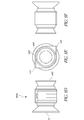
- FIGURES 1A-1I illustrate nine different views of an example of a removably attachable lens system for a communication device.
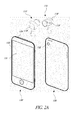
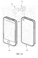
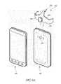
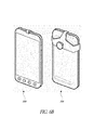
- FIGURES 2A-2B illustrate the lens system of Figures 1A-1I being attached to examples of communication devices.
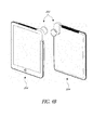
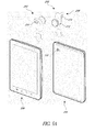
- FIGURES 3A , 3B , 4A , 4B , 5A , 5B , 6A , and 6B illustrate other examples of lens systems being attached to other examples of communication devices.
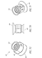
- FIGURES 7A-7I illustrate an example of a multiple lens system with a plurality of lenses used for different purposes.
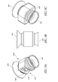
- FIGURES 8A-8I illustrate an example of a lens system with additional structures to facilitate attachment to a communication device.
- FIGURES 9A-9E illustrate additional views of the lens system of Figures 8A-8I .
- FIGURES 10A-10C illustrate the lens system of Figures 7A-7I being attached to an example of a communication device.
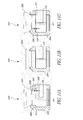
- FIGURES 11A-11F illustrate examples of lens systems with lens portions that are adjustable with respect to retainer portions.
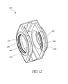
- FIGURE 12 illustrates an example of a lens retainer portion with an adjustment channel.
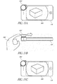
- FIGURES 13A-13C illustrate an example of a communication device on which an example of a lens system from Figures 11A-11F has been attached.
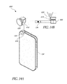
- FIGURES 14A-14B illustrate an example of a communication device with a light enhancement component on a lens system.
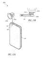
- FIGURES 15A-15B illustrate an example of a communication device with another light enhancement component on a lens system.
- FIGURES 16A-16F illustrate an example of a lens system that includes an adaptor.
- FIGURES 17A-17B illustrate an example of a lens component that includes a mount feature.
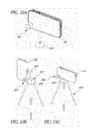
- FIGURES 18A-18C illustrate the lens component of FIGURES 17A-17B configured for mounting to a tripod.
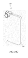
- FIGURES 19A-19C illustrate an example of a lens component that includes a storage or attachment feature along the side of the lens component for storing a lens or other device.
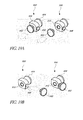
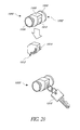
- FIGURE 20 illustrates examples of a lens system that includes an attachment to be used with an accessory such as a keychain.
- FIGURE 21 illustrates examples of a lens system that includes an attachment to be used with an accessory such as a necklace.
- FIGURE 22 illustrates examples of a lens system that includes an attachment to be used with an accessory such as a bracelet.
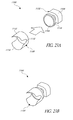
- FIGURES 23A-23E illustrate an example of a lens system that includes a lens hood.
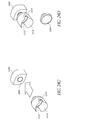
- FIGURES 24A-24D illustrate an example of a lens system that includes detachable lenses.
- FIGURE 25 illustrates an example of a lens system with an interior lens.
- the lens component 110 can generally comprise a retainer portion 112 and a lens portion 114.
- the retainer portion 112 is generally configured to be removably attachable to a communication device such that the lens portion 114 can be positioned in a region generally covering or near an onboard camera lens in the communication device to enable the lens portion 114 to cooperate optically with the onboard camera, to provide optical enhancements, improvements, modifications, and/or alternatives.
- the retainer portion 112 is shaped so as to attach to the communication device in a region and in a manner that permits a user to see all or virtually all of a viewing portion 131 of the communication device without obstruction or without appreciable obstruction.
- the retainer portion 112 can comprise a channel 116 with a plurality of sidewalls 118.
- the width of the channel 116 e.g., the distance between the respective sidewalls 118, can be configured to be generally complimentary to the thickness of a portion of the communication device(s) on which the retainer portion 112 is configured to attach.
- the natural width of the channel 116 is approximately the same size or slightly smaller than the thickness of a corner, such as an upper corner, of the outside housing of a communication device near the light aperture of the onboard camera of the communication device.
- one or more of the plurality of walls 118 can have a curvilinear shape 119 along one or more edges to permit the retainer portion 112 to provide increased distance of contact along the edge of the communication device while diminishing the area across a transverse surface of the device that is obstructed by the retainer portion 112.
- the curvilinear shape along one or more edges of the walls 118 permits the retainer portion 112 to extend along and attach to at least a portion of two generally converging or generally perpendicular outer edges or sides of a communication device that is approximately as wide as the lens portion 114, while diminishing the amount of space on the front of the device that is blocked.
- the curvilinear shape of the edge of the walls 118 can avoid or omit a lower pointed or sharp corner that may otherwise extend into and obstruct the viewing portion of the communication device.
- the retainer does not appreciably block or obstruct the viewing surface, as shown in Fig. 2B .
- All or part of the retainer portion 112, such as one or more of the plurality of walls 118, can be made of a material (e.g., a polymer or a silicone) that is sufficiently flexible to permit deformation (e.g., compression, bending, or stretching) of one or more walls 118, so that the channel 116 can be temporarily widened while sliding the lens component 110 onto a communication device, but at least a portion of one or more of the walls 118 can be sufficiently stiff, rigid, or resilient to urge one or more of the plurality of walls 118 to return to its original position and thereby exert a gripping force against a portion of the communication device.
- a material e.g., a polymer or a silicone
- the material of the retainer portion 112, especially the region on the inner side of the walls 118 within the channel 116, can also be tacky or somewhat slide resistant to enhance the gripping of the retainer portion 112 to the communication device.
- the gripping force and/or slide resistance can reduce or eliminate the need to attach a permanent or temporary mounting component to the communication device.
- the lens component 110 can be repeatedly attached to and removed from a communication device without requiring (though not prohibiting) installation on the communication device of a separate permanently or semi-permanently attached mounting component such as a bracket, magnet, adhesive, or other fastening component, thereby providing ease of installation while preserving the original overall shape, appearance, functionality, compatibility (e.g., with other communication devices or cases), and/or feel of the communication device when the lens component is removed.
- a separate permanently or semi-permanently attached mounting component such as a bracket, magnet, adhesive, or other fastening component
- the retainer portion 112 can also comprise an upper wall 120 that can be shaped in some embodiments to generally correspond to the shape of one or more edges of a communication device. As illustrated, the upper wall 120 has a generally curvilinear shape with a rounded corner 122.
- the retainer portion 114 can also include one or more internal surface contours 124 configured to generally avoid interference with one or more external features on a communication device.
- the channel 116 can include a surface contour 124 in the form of a groove to avoid interference or inadvertent contact with a button or other feature on a communication device when the lens component 110 is attached to the communication device.
- the sidewalls 118 of the retainer 112 can comprise one or more generally pointed or angular regions 129.
- the retainer portion 112 can be configured to grip two nonparallel sides of a communication device.
- the retainer portion 112 can contact at least a first generally vertical side or edge surface 133 of a communication device and at least a second generally horizontal and generally orthogonal side or edge surface 134 of a communication device (e.g., the lateral side and the top side of the communication device) at the same time during use.
- this contact by multiple generally perpendicular edges or surfaces permits repeatable adequately precise placement of the retainer portion 112 in a single attachment motion without requiring user adjustment of the location or structure of the retainer portion 112 during attachment.
- two or more contacting surfaces in the retainer portion 112 can converge at an upper corner having a rounded external surface.
- the retainer portion 112 is substantially smaller than the communication device to which it is configured to attach, or even substantially smaller than the viewing portion of the communication device to which it is configured to attach.
- a retainer can be configured to contact only one side or edge (e.g., the generally vertical or the generally horizontal side or edge), such as by contacting both the front and rear surface of such side of edge but without also requiring contact with another side or edge.
- An example of such an embodiment can generally be formed from a retainer portion with a general U-shape comprising an upper wall, two side walls, and an opening on each side of the side walls.
- the retainer portion 112 can permit the lens component 110 to be attached to a communication device without requiring non-stock mounts on the communication device and without requiring dynamic mounts on the retainer portion 112 itself (e.g. fasteners, screws, adjustable clamps, etc.).
- a user can attach the lens component 110 to a corner of a communication device by simply sliding it, for example, onto the corner of the communication device, and can remove it by simply pulling it off, without requiring user adjustment during attachment.
- the lens component 110 can remain on the communication device by way of a friction fit.
- the attachment to the communication device can avoid a residue deposit from adhesive, scratches to the exterior surface, or other damage or alteration of the communication device.
- the retainer portion can be sufficiently wide and/or long so that it is adapted to receive an end and/or side region (e.g., two or more corners) of a communication device rather than merely one corner, and the other aspects of other embodiments disclosed herein can apply to such embodiments, including but not limited to the shape and materials of construction and the accomplishment of a friction fit between the retainer portion and the end and/or side region of a communication device.
- an end and/or side region e.g., two or more corners
- the lens portion 114 generally comprises a transparent lens 128, which is typically made of a glass or a polymer, and a securing structure 126.
- the securing structure 126 can be made of many different types of materials or combinations of materials, such as metals (e.g., aluminum or steel) or plastics.
- the securing structure 126 can include a generally wide-area opening for receiving the lens 128 and a generally narrow-area region for attachment to the retainer portion 112.
- the securing structure 126 and the retainer portion 112 can be configured to slide or otherwise move with respect to each other in a limited manner to allow for adjustment of the position of the lens 128 with respect to the onboard camera lens of a communication device (e.g., for the purpose of addressing manufacturing tolerances in the location of the onboard camera lenses in some communication devices).
- the mechanism or structure for attachment or securement of the lens portion 114 to the retainer portion 112 can be separate from and/or can operate independently of the mechanism or structure for attachment or securement of the retainer portion 112 to the communication device.
- the outside surface of the securing structure 126 can taper inwardly from the lens-receiving region to the retainer-attaching region to diminish the amount of material used in manufacturing and to diminish the size and weight of the retainer lens portion 114.
- the lens component can be very small, such as less than or equal to about 2 1 ⁇ 2 inches or less than or equal to about 1 1 ⁇ 2 inches across.
- the lens 128 can include multiple lenses or lens components.
- the lens component 110 can comprise more complex lensing systems, such as lensing systems in which the focal length of the lensing system can be manually or electronically adjusted, such as with a lever or rolling dial or with electronic or motor control, which may be positioned between the lens 128 and the retainer portion 112.
- An electronic or motor control can be attached and adjusted using software in the communication device, either by a wired or wireless connection to the mobile communication device.
- Other specialized lenses in the lensing system can include a telephoto lens systems configured to enlarge images, wide-angle lenses, fish-eye lenses, macroscopic lenses, and microscopic lenses.
- the lens 128 can also comprise coatings or other features to increase scratch resistance, diminish glare or reflection, or decrease or filter light transmitted through the lens 128.
- the lens component 110 can also include a cover configured to be fitted over the lens 128 during storage and transportation.
- the lens component 110 can comprise other storage and transportation features, such as a quick-release or other attachment structure to enable the lens component 110 to be conveniently carried by a user on a standard accessory carried by a person, such as a key ring, belt loop, bracelet, necklace, or other easily accessible location when not attached to a communication device.
- a collection or kit of different lens components 110 with various lenses having different lens features, including those described herein, can be provided within a storage case to address various photographic needs.
- the lens component 110 can be moved into proximity with a communication device 130, 134 that includes an onboard camera 132.
- a lens component 110 can be sold or provided together as a system with the communication device 130, 134.
- the communication devices 130, 134 shown in Figures 2A-2B and 3A-3B are versions of the iPhone mobile phone sold by Apple, Inc.
- the lens component 110 can be oriented so that the channel 116 is directed downwardly in general alignment with an edge or corner of the communication device 130 on which the lens component 110 will be mounted and rotated so that the lens 128 will be generally aligned with the onboard camera 132.
- the channel 116 may expand slightly as the walls 118 flex or bend outwardly.
- a restoring force produced by the retainer portion 112 can urge the walls 118 back toward their original position, which can help to retain the lens component 110 on the communication device 130 during use.
- the lens 128 can then temporarily provide an enlarged, better focused, clearer, or otherwise enhanced, altered, manipulable, or improved image for the onboard camera 132.
- Figures 4A-4B and 5A-5B illustrate examples of lens components 200, 202 configured to be used on tablet-type communication devices 204, 206.
- the communication device 204 is an iPad communication device sold by Apple, Inc.
- the communication device 206 is a Galaxy tablet sold by Samsung.
- the lens components 200, 202 can include various features and structures of the lens component 110 illustrated and described in connection with Figures 1A-1I .
- the lens components 204, 206 can include a retainer portion 208 with walls 210, 212 of different sizes and lengths.
- a longer or wider-area wall 212 can be provided on a side of the retainer portion 208 that is configured to suspend the lens 128 in front of the camera 132, while a shorter or smaller-area wall 210 can be provided on a side of the retainer portion 208 that is configured to extend over a portion of the surface on which the viewing portion of the communication device 204, 206 is located.
- the retainer portion 208 can be configured to securely attach the lens components 200, 202 while diminishing or eliminating obstruction of the viewing portion.
- An aperture or other functional access region 216 can be provided in the retainer portion 208 to permit access to controls or other interaction structures on the communication devices 204, 206 when the lens components 200, 202 are attached.
- Figures 6A-6B illustrate an example of a lens component 302 with a retainer portion 308 that comprises a plurality of attachment arms 304 that include attachment structures, such as hook portions 306, that can partially or completely overhang on a portion of a communication device 306 or that are oriented in a generally transverse direction to the main portion of the attachment arms 304.
- the attachment arms 304 can be generally tapered from a central, wider portion to a peripheral, narrower portion to provide sufficient structural rigidity and retaining force.
- the lens component 302 can include the various features of the other lens components 110, 200 described herein.
- the communication device illustrated in Figures 6A-6B is an EVO communication device sold by HTC Corporation.
- the attachment arms 304 can assist in attaching the lens component 302 to a device, such as the EVO device, in which the camera 310 is not positioned near a corner of the device.
- Figures 7A-7I illustrate several views of an example of a lens component 400 in which a plurality of lenses 402, 404 can be attached to the same retainer portion 406.
- the user can have at least two different options for the type of lens to use in a particular photographic application.
- one of the lenses 402, 404 can provide a wide-angle view and another one of the lenses 402, 404 can provide a fish-eye view.
- Many other lens options are possible.
- one or more lenses can be provided with different color filtering capabilities, different light attenuation capabilities, different lens coatings (such as anti-reflection coatings), and differences in other optical properties to provide multiple user options. Different lenses can include any combinations of these or other optical features.
- the retainer portion 406 can include various features of the other retainer portions illustrated and described herein.
- Figures 8A-8I and 9A-9E illustrate several views of an example of a lens component 400a that is similar or identical in many ways to lens component 400 in Figures 7A-7I .
- Lens component 400a includes a channel 416 for receiving a portion of a communication device.
- the channel 416 includes an attachment-facilitating surface 418.
- the attachment-facilitating surface 418 comprises an inwardly curved (e.g., sloped or slanted) surface positioned along the outer edge or slotted opening of the channel 416.
- the attachment-facilitating surface 418 can be positioned at or near an outer edge of the channel 416. As illustrated, the attachment-facilitating surface can be thinner near the edge and can gradually become thicker as it progresses further into the channel 416.
- the attachment-facilitating surface 418 can provide an initial contact region or opening 420a (see, e.g., Figs. 8G and 8H ) near the outer edge 422 that is effectively wider to facilitate proper orientation and attachment of the device by a user, and a narrower second region 420b further within the channel 416 (or further from the edge of the lens component 400a), thereby providing a more secure attachment surface as the lens component 400a is moved further onto the attachment region of the communication device.
- the width of the channel 416 can change between the initial contact region 420a and the second region 420b in a smooth, gradual, and/or curvilinear manner.
- attachment-facilitating surface 418 can include a discontinuous surface or a series of discrete ramps, protrusions, or grooves.
- An attachment-facilitating surface 418 can be included on any embodiment of a lens component and is not limited to use in the lens component 400a as illustrated in Figures 8A-8I and 9A-9E .
- the user can select which of the plurality of lenses 402, 404 to position in front of the camera 132 of the communication device 134 to achieve a desired photographic affect.
- the lens component 400 is moved into an attachment position on a communication device 134 such that a first (e.g., smaller-diameter) lens 402 is positioned in front of the onboard camera lens 132 and a (e.g., second larger-diameter) lens 404 is positioned on an opposite side of the communication device 134.
- a first (e.g., smaller-diameter) lens 402 is positioned in front of the onboard camera lens 132 and a (e.g., second larger-diameter) lens 404 is positioned on an opposite side of the communication device 134.
- the smaller-diameter lens 402 is operative and the larger-diameter lens 404 is not operative.
- the lens component 400 is removed from the communication device, rotated about a vertical axis (e.g., approximately 180° in this example), and rotated about a horizontal axis to orient the channel 416 in general alignment with an attachment surface (e.g., a housing edge) of the communication device.
- the lens component 400 is again advanced onto the communication device 134 such that the larger-diameter lens 404 is positioned in front of the onboard camera lens 132 and the smaller-diameter lens 402 is positioned on an opposite side of the communication device 134. In this orientation, the larger-diameter lens 404 is operative and the smaller-diameter lens 402 is not operative.
- this configuration of a lens component 400 can conveniently permit multiple lens options without necessarily requiring the user to hold or store multiple discreet lens components. In some embodiments, more than two lens types or features can be included in the lens component 400, thereby providing the user with many lens options.
- FIGS 11A-11F illustrate several views of an example of a lens component 500 in which a lens 502 is attached to a retainer portion 504.
- the lens component 500 can be attached to a communication device 134 in a manner similar to the lens components described above.
- the user can adjust (e.g., tilt, swivel, or otherwise move) the lens 502 with respect to the communication device 134 (e.g., azimuthally, along the lens's vertical axis, along the lens's horizontal axis, a combination of these adjustments, etc.).
- the user can shift or otherwise move the lens 502 into a plurality of positions with respect to the retainer to diminish misalignment between the onboard lens in the communication device, or to change the viewing angle of the lens 502, or for some other reasons.
- the user can shift of otherwise move the lens 502 into at least a first and a second position, or at least a first, a second, and a third position, or gradually across an adjustment zone.
- this adjustment can form a void 506 behind the lens portion 502.
- the ability to adjust the lens 502 with respect to the communication device 134 can be advantageous in addressing manufacturing differences or tolerances in the location and/or alignment of the onboard camera lenses in some communication devices.
- the tilting of the lens 502 is facilitated by a pivot (not shown) on the portion of the lens facing the communication device 134.
- the lens 502 is positioned in a channel formed by sidewalls 508 of the retainer portion 504.
- the lens 502 is tilted to the left with respect to the communication device 134 such that a void 506 is formed between the rear of the lens 502 and a panel of the retainer portion 504 or the communication device 134 when attached, and the exterior walls of the lens portion 502 are non-parallel with the adjacent interior walls of the lens retainer portion 502.
- the lens 502 can compensate for an off-center alignment of the onboard camera of the communication device 134.
- the central axis of the lens portion 502 can be brought into general alignment with the central axis of the onboard camera lens 132.
- Figure 11B illustrates the lens 502 in a neutral position with respect to the communication device 134. In this orientation, the lens 502 need not compensate for any off-center alignment of the onboard camera of the communication device 134.
- Figure 11C illustrates the lens 502 tilted to the right with respect to the communication device 134, forming a void 506 in a manner similar to Figure 11A .
- the lens 502 can compensate for a difference or off-center alignment or location of the onboard camera of the communication device 134.
- the tilting of the lens 502 is facilitated by a ball and socket joint formed by a ball 510 on the portion of the lens 502 facing the communication device 134 and a socket 512 in the retainer portion 504.
- This embodiment can generally function in a manner similar to the embodiment in Figures 11A-11C .
- the ball portion 510 can approximate the shape of a generally oblate spheroid and can have one or more flat or straight portions.
- the ball portion 510 can be, but is not required to be, generally spheroid.
- the portion facing the communication device 134 is generally straight or flat.
- the ball 510 can be positioned within a socket 512 with a generally complementary shape, facilitating rotation of the lens 502 with respect to the retainer portion 502 and communication device 134.
- the lens 502 is tilted to the left with respect to the communication device 134 such that a void 506 is formed between the ball 510 and socket 512 or the communication device 134. In this orientation, the lens 502 can compensate for miscorrespondence in the alignment or location of the onboard camera of the communication device 134.
- Figure 11E illustrates the lens 502 in a generally neutral position with respect to the communication device in which at least one wall of the retainer portion 504 can be generally parallel with either or both of the front or back surfaces of the lens portion 502.
- Figure 11F illustrates the lens 502 tilted to the right with respect to the communication device 134, forming a void 506 in a manner similar to Figure 11D .
- the lens 502 can compensate for miscorrespondence in the alignment or location of the onboard camera of the communication device 134 or otherwise help to adjust the nature of the photographic image produced.
- at least one wall of the retainer portion 504 can be generally non-parallel with either or both of the front or back surfaces of the lens portion 102. As illustrated, the user can appropriately adjust the lens portion 502 with respect to the lens retainer portion 504.
- the lens retainer portion 504 can include one or more generally circular retaining walls 530 for receiving a lens portion 502 in an adjustable manner.
- the retaining walls 530 can include one or more apertures 535.
- a radially interior surface 537 of either or both of the apertures 535 can include a first adjustment structure, such as an adjustment channel 540 with a width and depth configured to receive a second adjustment structure on the lens portion 502, such as a ridge or bump.
- the adjustment channel 540 can be substantially smaller in width than the width of the interior surface 537 of the aperture 535 to provide a relatively small amount of restricted movement of the lens portion 502.
- the width of the adjustment channel 540 can be less than or equal to about 1.5 mm, and the interior of the adjustment channel 540 can be tapered or beveled toward a generally central portion or line to increase the force required to move the lens portion 502 away from a neutral position.
- the width of the ridge or bump on the lens portion 502 can be less than the width of the adjustment channel 540, such as less than or equal to about 3 ⁇ 4 of the width of the adjustment channel 540.
- the first and second adjustment structures can fit closely or tightly together (e.g., in a radial interference fit) while permitting limited movement when a force is applied by a user in opposition to frictional forces between the adjustment structures.
- the lens portion 502 can be adjusted by a user to move with respect to the lens retainer portion 504 when moved in a deliberate manner, but the lens portion 502 and retaining portion 504 can generally remain in place until another adjustment.
- the amount of adjustment can be relatively small, such as greater than or equal to about 0.5 degrees and/or less than or equal to about 2.5 degrees between the orientation of the central longitudinal axis of the lens portion 502 in the original position as compared to the orientation of the central longitudinal axis of the lens portion 102 in the fully adjusted position.
- the lens portion 502 can be adjusted to various positions between (or outside of) these points or ranges.
- the amount of movement between the rear surface of the lens portion 502 and the lens retainer portion 504 can be relatively small as well, such as greater than or equal to about 0.1 mm and/or less than or equal to about 1.0 mm between the original orientation and the fully adjusted orientation.
- the user can adjust the tilt of the lens 502 with respect to the communication device 134 to improve the alignment or other correspondence between the lens 502 and the onboard camera of the communication device 134.
- the lens 502 is in a neutral position with respect to the communication device 134.
- the image on the screen 560 of the communication device 134 is off-center to the left, as evidenced by the leftward orientation of the vignetting which would normally be centered about the image.
- Figure 13B shows the user 590 tilting the lens 502 to the right to compensate for the off-center image on the communication device 134.
- Figure 13C illustrates the corrected image, with the vignetting centered about the image even though the onboard camera of the communication device is not aligned properly.
- the tilt of the lens 502 can be adjusted while the user 590 is viewing a live image from the onboard camera on the screen 560 of the communication device 134, providing real-time feedback to the user about whether the correct adjustment is being made.
- Figures 14A-14B illustrate two views of a lens component 600 with a lens portion 630 and a light-enhancing feature, such as a light pipe 610.
- the light pipe 610 can be mounted to the retainer portion 660 or to some other portion of the lens component 600.
- the light pipe 610 conveys light from a light source, such as a flash, to an exit point 620 so that it may illuminate the area to be photographed.
- the light pipe 610 is made from material which facilitates conveyance of light from the flash to the area to be photographed.
- the interior of the light pipe 610 is lined with material which facilitates conveyance of light from the onboard flash to the area to be photographed.
- the position of the flash 650 on the communication device 134 illustrated in Figures 14A-14B is close enough to the onboard camera 132 that the lens component 600 generally covers or otherwise obstructs the flash 650 when it is attached to the communication device 134. In some circumstances, this may prevent light from the flash 650 from enhancing photographs taken when the lens component 600 is attached.
- the light pipe 610 conveys the light from the flash 650 to the exit point 620, and from there the light travels normally to illuminate the area in front of the camera.
- the light pipe 610, retainer portion 660, and/or some other portion of the lens component 600 can be configured to generally or entirely surround the flash 650 and/or other region from which light emanates to inhibit or prevent undesirable light transfer or leakage outside of the pathway from the onboard flash into the light pipe 610.
- Such an undesirable transfer or leakage may include light from the onboard flash moving into the rear side of the lens portion 630 of the lens component 600 or light from the onboard flash moving outside of the region between the retainer portion 660 of the lens component 600 and the communication device.
- the retainer portion 660 or another component can be formed from various materials, including polymers (e.g., polycarbonate), metals (e.g., aluminum), etc., or some combination thereof.
- the retainer portion 660 can be formed using a multi-step molding process, such as multi-shot injection molding, inserting molding, or overmolding, and/or the retainer portion 660 can include a coating, such as an adhesive, paint, or deposited film, to provide a region on the interior and/or exterior of the retainer portion 660 that has a different durometer or appearance than another portion of the retainer portion 660.
- a harder shell or exterior can be provided in conjunction with a softer interior surface.
- an interior region of the retainer portion 660 that is intended to be positioned in contact with the corner of the communication device can comprise a surface that is softer and/or more tacky than an exterior region or a supporting region of the retainer portion 660.
- the softer or more tacky surface can provide an enhanced light seal by compressing against the communication device to inhibit or prevent light leakage.
- Figures 15A-15B illustrate two views of a lens component 600a with a light pipe 610a.
- the light pipe 610a is similar or identical to the light pipe 610 described above.
- the exit point 620a of the light pipe 610a can generally or completely surround the lens 630a, providing a generally ring-shaped flash. This can be particularly desirable for use in macro (or close-up) photography.
- the light-enhancing feature can also be provided by a flash or other light source on the lens component 600, without requiring use or connection with an onboard flash.
- a light-enhancement feature can include an externally attachable flash component connected to the lens component 110 that can be selectively configured to be in electronic communication with the communication device (e.g., by way of a wireless protocol such as the Bluetooth® protocol, or by way of a wired connection such as a USB or serial connection, etc.).
- the flash can be powered by and/or actuated by the communication device.
- the flash can pivot, tilt, or otherwise move with respect to the retainer portion 112 to direct light as desired by the user.
- lens components can include retainer portions with attachment structures configured to be removably attached to communication devices, even when the communication devices themselves are generally smooth or flat and do not have corresponding attachment structures in the region near the onboard camera.
- the communication devices are not required to be permanently or temporarily modified, reconfigured, defaced, or otherwise altered in appearance to permit attachment of the lens components.
- this arrangement can permit uninterrupted and unobstructed, normal use of the communication device when the lens component is removed.
- modifications to the communication devices may be useful or necessary to attach the lens components.
- FIGS 16A-16F illustrate views of a lens system 700.
- the lens system 700 can include a lens component 702.
- the lens component 702 can be similar to other lens components described herein.
- the lens component 702 can comprise similar or identical structures as lens component 400 or 400a.
- the lens component 702 can include one or more lenses 704, 706 that are attached to (e.g. releasably coupled to, or integrally formed with) the same retainer portion 708.
- the user can have at least two different options for the type of lens to use in a particular photographic application.
- one of the lenses 704, 706 can provide a wide-angle view and another one of the lenses 704, 706 can provide a fish-eye view.
- the retainer portion 708 can include various features of the other retainer portions illustrated and described herein.
- the retainer portion 708 can include a channel 709.
- the lens system 700 can further include an adaptor 710.
- the adaptor 710 can comprise a separate or independent piece from that of the lens component 702.
- the adaptor 710 can include a first adaptor connection portion 712.
- the first adaptor connection portion 712 can be configured to be removably attachable to a communication device 720 that has a shape that is different from the standard communication device to which the lens component 702 is normally configured to attach, for example as shown in Figure 16D .
- the first adaptor connection portion 712 can include a channel 714.
- the channel 714 can be sized and/or shaped to correspond to the size and/or shape of at least a portion of the communication device 720, such that the adaptor 710 can slide over a portion (e.g. a corner) of the communication device 720, and be held in place on the communication device 720 (e.g., by way of a friction fit).
- the adaptor 710 can further include a second adaptor connection portion 716.
- the second adaptor connection portion 716 can be sized and/or shaped such that it is received within the channel 709 on the lens component 702.
- the second adaptor connection portion 716 can include at least one opening 718 to permit optical communication between the lens 704, 706 and a corresponding onboard camera 722 on the communication device 720.
- the adaptor 710 and lens component 702 can be positioned such that the lens 704, 706 is positioned in a region generally covering or near the onboard camera 722 in the communication device 720 to enable the lens 704, 706 to cooperate optically with the onboard camera, to provide optical enhancements, improvements, modifications, and/or alternatives.
- the adaptor 710 and lens component 702 are shaped so as to attach to the communication device 720 in a region and in a manner that permits a user to see a viewing portion of the communication device 720 without obstruction or without appreciate obstruction.
- the lens component 702 can be removably attached to the adaptor 710 in a variety of manners.
- the lens component 702 can be attached solely via a friction fit between the retainer portion 708 and the second adaptor connection portion 716.
- the lens component 702 can snap into place on top of the adaptor 710. Other attachment options are also possible.
- the adaptor 710 can allow the lens component 702 to be used with one or more different communication devices.
- the adaptor 710 can allow the lens component 702 to be used with a communication device that is different in size, thickness, and/or shape than one that the lens component 702 is typically designed for.
- the communication device 720 can comprise an iPod Touch device, manufactured by Apple, Inc.
- another communication device 134 can comprise an iPhone, also manufactured by Apple, Inc.
- the iPhone is typically larger, and thicker, than the iPod Touch. If the lens component 702 is designed and sized to specifically fit onto the iPhone, but not onto the iPod Touch, the user can conveniently and simply use the adaptor 710 in order to use the lens component 702 with the communication device 720.
- FIGS 17A-17B illustrate an example of an attachment component 800 for use in applications where a communication device is intended to be mounted temporarily on a support structure to take a photo or video.
- the attachment component 800 can include one or more lenses 802, 804 that are attached to the same retainer portion 806.
- the retainer portion 806 can include a channel 808, similar or identical to the channels described above, for attaching the attachment component 800 to a portion (e.g. corner) of the communication device 134.
- the retainer portion 806 can further include stabilizing or securing members such as at least one or more elongate ridges 810, 812.
- the elongate ridges 810, 812 can extend away from the lens 802, 804, and can be used to grasp onto and/or hold the attachment component 800 in place on the communication device 134.
- the width of the elongate ridges 810, 812 is less than the thickness of the communication device to which the lens component is configured to attach and the elongate ridges 810, 812 extend across the front viewing surface of the communication device along a narrow front edge and terminate before obscuring any appreciable portion of the viewing area.
- the retainer portion 806 can also include a connector opening 814 at one end of the attachment component 800.
- the attachment component 800 can be attached to the communication device 134 (e.g. iPhone), such that the elongate ridges 810, 812 extend over and grasp onto a side edge 816 of the communication device 134.
- the ridges 810, 812 can help to hold the attachment component 800 in place on the communication device 134.
- Other types of structure, other than ridges 810, 812 can also be used.
- the attachment component 800 can be attached to a support structure 818 (e.g. a tripod).
- attachment component 800 can be attached to a base portion 820 of the support structure 818.
- the base portion 820 can be screwed into, or otherwise attached to, the retainer portion 806 of the attachment component 800.
- the connector opening 814 can include internal threading, and the base portion can include a screw or other structure that has external threads, such that the base portion 820 can be screwed into the connector opening 814.
- Other types of connection are also possible, including a snap-fit or other type of connection mechanism that permits a quick, releasable connection between the attachment component 800 and the support structure 818.
- the base portion 820 of the support structure 818 can either include, or be connected with, a mounting arm 822.
- the retainer portion 806 of the attachment component 800 can comprise the mounting arm 822.
- the mounting arm 822 can be used to adjust the position of the communication device 134.
- the communication device 134 is in a generally horizontal or landscape position on top of the support structure 818, whereas with the mounting arm 822, as illustrated in Figure 18B , the communication device 134 is positioned to a side of the base portion 820, and is in a vertical position.
- Other types of mounting arms or structures are also possible.
- the attachment component 800 comprises one or more lenses, and in some embodiments, the attachment component 800 has no lenses.
- Figures 19A-19C illustrate a lens component 900 that permits storage of additional lenses, lens caps, or other devices.
- the lens component 900 can include one or more lenses 902, 904 that are attached to the same retainer portion 906.
- the retainer portion 906 can include a channel (not shown), similar to the channels described above, for attaching the lens component 900 to a portion (e.g. corner) of the communication device 134.
- the lens component 900 can further include at least one attachment feature 908.
- the storage attachment feature 908 can comprise an opening, ridge, button, or other structure located generally orthogonally along the lens component 900 that is configured to contact, hold, and/or receive a device.
- the attachment feature 908 can comprise an opening configured to receive a portion of lens 902.
- the storage attachment feature 908 can be located on the retainer portion 906.
- the storage attachment feature 908 can attach (e.g. releasably attach) to a plurality of different sized lenses, including but not limited to lenses 902 and/or 904 as illustrated.
- the storage attachment feature 908 can also, or alternatively, releasably attach to a lens cap (not shown), or other types of devices.
- the storage attachment feature 908 can permit one or more devices (e.g. lenses) to be stored and/or carried along a side of the lens component 900 until needed for use.
- the device can be removed from the storage attachment feature 908, and attached along a different area of the lens component 900.
- the lens 902 can be removed from an opening 910 along the retainer portion 906.
- the opening 910 can include threads or other structure generally for holding the lens 902.
- the lens 902 can be attached to the storage attachment feature 908 along the side of the lens component 900, as illustrated in Figure 19B . At such time, a different lens can then be inserted into the opening 910 if desired.
- the lens 902 can be removed from the storage attachment feature 908, and again placed back into the opening 910.
- FIGS 20-22 illustrate examples of a lens system 1000 that are used with person-carried accessories such as keys, necklaces, bracelets, or other devices.
- the lens system 1000 can include a lens component 1002.
- the lens component 1002 can be similar or identical to any of the lens components described herein.
- the lens component 1002 can be similar to lens component 400 or 400a.
- the lens component 1002 can include one or more lenses 1004, 1006 that are attached to the same retainer portion 1008.
- the retainer portion 1008 can include various features of the other retainer portions illustrated and described herein.
- the retainer portion 1008 can include a channel 1010.
- the lens system 1000 can include an attachment component such as a plug 1012.
- the attachment component can be configured to remain on or connected with a person-carrier accessory, while the lens component 1002 can be selectively detached during use.
- the plug 1012 can be sized and shaped so as to be received by the channel 1010.
- the plug 1012 can include one or more accessory attachment features 1014.
- the accessory attachment feature 1014 can comprise, for example, a small ring or half-ring that protrudes from the rest of the plug 1012.
- the accessory attachment feature 1014 can be attached to a set of keys 1016, necklace 1018, bracelet 1020, or any other similar device.
- the lens system 1000 can allow a user to wear and/or carry the lens component 1002 with him or her, in an easy and convenient manner.
- the lens component 1002 can be quickly removed from the plug 1012 and used with a communication device, such as one of the communication devices described herein, and then returned again to the plug 1012 and/or keys 1016, as illustrated in Figure 20 , necklace 1018 as illustrated in Figure 21 , bracelet 1020 as illustrated in Figure 22 , etc. once the user is done.
- Figures 23A-23E illustrate an example of a lens system 1100 that can be used to reduce lens flare and protect a lens.
- the lens system 1100 can include a lens component 1102.
- the lens component 1102 can include structures that are similar or identical to the lens components described herein.
- the lens component 1102 can be similar to lens component 110.
- the lens component 1102 can include one or more lenses 1104 that are attached to the same retainer portion 1106.
- the retainer portion 1106 can include various features of the other retainer portions illustrated and described herein.
- the retainer portion 1106 can include a channel (not shown).
- the lens system 1100 can further include a lens hood 1108.
- the lens hood 1108 can be a separate piece that is configured to attach to the lens component 1102.
- the lens hood 1108 can comprise an opening 1110 configured to fit over the lens 1104.
- the lens hood 1108 can comprise flared portions 1112, 1114 that extend away from the opening 1110.
- the flared portions 1112, 1114 can be configured to provide protection for the lens 1104, so as to reduce lens flare.
- the lens hood 1108 can be releasably attached to the lens 1104, for example by simply sliding the opening 1110 of the lens hood 1108 over an edge 1116 of the lens 1104.
- the lens hood 1108 can be held in place via friction fit, though other connection mechanisms are also possible.
- the flared portions 1112, 1114 can be positioned as desired by twisting or rotating the lens hood 1108. The flared portions 1112, 1114 can then protect the lens 1104 while the lens 1104 is in use.
- the lens hood 1108 can be removed from the lens component 1102, turned around 180 degrees, as illustrated in Figures 23C-23E , and placed back over the lens 1104. In this position, the lens hood 1108 can not only be easily stored for future use, but can also help to protect the lens 1104 and/or lens component 1102 from damage and/or wear.
- Figures 24A-24D illustrate an example of a lens system 1200 that can include a selectively attachable and detachable lens or a plurality of different selectively attachable and detachable swappable lenses.
- the lens system 1200 can include a lens component 1202.
- the lens component 1202 can be similar to one of the lens components described herein.
- the lens component 1202 can be similar to lens component 110.
- the lens component 1202 can include one or more lenses 1204 that are attached to the same retainer portion 1206.
- the retainer portion 1206 can include various features of the other retainer portions illustrated and described herein.
- the retainer portion 1206 can include a channel (not shown).
- the lens system 1200 can include the ability to swap lenses.
- the lens component 1204 can be removably attached to the retainer portion 1206.
- the retainer portion 1206 can include a lens attachment portion 1208.
- the lens 1204 can be removably attached to the retainer portion 1206 at the lens attachment portion 1208.
- the lens attachment portion 1208 can comprise an opening with threads, and the lens 1204 (or other lens) can be screwed into the opening 1208, or the lens can snap-fit or otherwise simply be pushed into the opening 1208.
- Other connection mechanisms are also possible.
- the lens can be temporarily locked in with a bayonet mount, or a magnetic mount or other structure can be used.
- the lens system 1200 can further include one or more additional lens components, such as a second lens component 1210.
- the second lens component 1210 can comprise a lens 1212 with a lens hood 1214.
- the second lens component 1210 can be a separate piece that is configured to attach to the retainer portion 1206, similar to lens 1204.
- the second lens component 1210 can be attached to the lens attachment portion 1208.
- a user can select a lens 1204, a lens 1212 with hood 1214, or other types of lenses for use with the lens system 1200.
- Figure 25 illustrates an example of the lens system 1200 that includes one or more interior lens components.
- the lens system 1200 can include an embedded lens component 1216.
- the retainer portion 1206 or the embedded lens component 1216 can comprise a connection portion, such as a threaded portion, that can be similar to the lens attachment portion 1208, described above.
- the threaded portion can facilitate removably attaching lenses, such as lens 1204, to the retainer portion 1206.
- the retainer portion 1206 and/or the embedded lens component 1216 can include a lens 1218.
- the embedded lens component 1216 can be generally flush with or inset within the walls of the retainer portion 1206.
- the lens 1218 can be a macro lens configured to magnify an image by at least about 4x magnification. Many different magnifications are possible. In some embodiments, the lens 1218 can be a macro lens configured to apply a magnification of at least about 5x magnification and/ less than or equal to about 15x magnification, etc. In some embodiments, multiple lenses can be configured to provide a variable optical magnification (e.g., a zoom feature) by permitting manipulation of the distance between the lenses, such as with a lever or rotating actuator (e.g., a thumb wheel).
- a variable optical magnification e.g., a zoom feature
Landscapes
- Physics & Mathematics (AREA)
- General Physics & Mathematics (AREA)
- Optics & Photonics (AREA)
- Engineering & Computer Science (AREA)
- Multimedia (AREA)
- Signal Processing (AREA)
- Structure And Mechanism Of Cameras (AREA)
- Accessories Of Cameras (AREA)
- Lens Barrels (AREA)
- Telephone Set Structure (AREA)
Priority Applications (1)
| Application Number | Priority Date | Filing Date | Title |
|---|---|---|---|
| EP15178139.0A EP2966486A1 (fr) | 2011-03-18 | 2012-03-15 | Lentilles pouvant être fixées de manière sélective pour dispositifs de communication |
Applications Claiming Priority (4)
| Application Number | Priority Date | Filing Date | Title |
|---|---|---|---|
| US201161454136P | 2011-03-18 | 2011-03-18 | |
| US201161503835P | 2011-07-01 | 2011-07-01 | |
| US201261585857P | 2012-01-12 | 2012-01-12 | |
| US13/366,227 US8279544B1 (en) | 2011-03-18 | 2012-02-03 | Selectively attachable and removable lenses for communication devices |
Related Child Applications (2)
| Application Number | Title | Priority Date | Filing Date |
|---|---|---|---|
| EP15178139.0A Division EP2966486A1 (fr) | 2011-03-18 | 2012-03-15 | Lentilles pouvant être fixées de manière sélective pour dispositifs de communication |
| EP15178139.0A Division-Into EP2966486A1 (fr) | 2011-03-18 | 2012-03-15 | Lentilles pouvant être fixées de manière sélective pour dispositifs de communication |
Publications (2)
| Publication Number | Publication Date |
|---|---|
| EP2500758A1 true EP2500758A1 (fr) | 2012-09-19 |
| EP2500758B1 EP2500758B1 (fr) | 2015-09-02 |
Family
ID=45930998
Family Applications (2)
| Application Number | Title | Priority Date | Filing Date |
|---|---|---|---|
| EP15178139.0A Withdrawn EP2966486A1 (fr) | 2011-03-18 | 2012-03-15 | Lentilles pouvant être fixées de manière sélective pour dispositifs de communication |
| EP12159634.0A Not-in-force EP2500758B1 (fr) | 2011-03-18 | 2012-03-15 | Lentilles pouvant être fixées et amovibles de manière sélective pour dispositifs de communication |
Family Applications Before (1)
| Application Number | Title | Priority Date | Filing Date |
|---|---|---|---|
| EP15178139.0A Withdrawn EP2966486A1 (fr) | 2011-03-18 | 2012-03-15 | Lentilles pouvant être fixées de manière sélective pour dispositifs de communication |
Country Status (8)
| Country | Link |
|---|---|
| US (7) | US8279544B1 (fr) |
| EP (2) | EP2966486A1 (fr) |
| JP (1) | JP5886881B2 (fr) |
| KR (1) | KR101571509B1 (fr) |
| CN (2) | CN103869444A (fr) |
| BR (1) | BR112013005617B1 (fr) |
| MX (1) | MX2013010452A (fr) |
| WO (1) | WO2012128936A1 (fr) |
Cited By (18)
| Publication number | Priority date | Publication date | Assignee | Title |
|---|---|---|---|---|
| CN103345033A (zh) * | 2013-07-08 | 2013-10-09 | 谢虹 | 一种手机镜头放大器 |
| CN103916495A (zh) * | 2012-11-10 | 2014-07-09 | 罗天成 | 一种新型智能终端和与智能终端连接的壳体 |
| WO2015048143A1 (fr) * | 2013-09-26 | 2015-04-02 | Olloclip, Llc | Systèmes optiques pour dispositifs mobiles pouvant être fixés et retirés de manière sélective |
| CN104967764A (zh) * | 2015-06-16 | 2015-10-07 | 成都西可科技有限公司 | 一种运动相机摄像头的防偏结构 |
| WO2016077661A1 (fr) * | 2014-11-13 | 2016-05-19 | Medtronic Vascular, Inc. | Outil d'évaluation visuelle et tactile à fixer sur un dispositif mobile |
| EP2936229A4 (fr) * | 2012-12-21 | 2016-06-08 | Intel Corp | Accessoire auxiliaire d'objectif d'appareil-photo et conduit de lumière pour dispositif électrique |
| EP3079097A1 (fr) * | 2015-04-08 | 2016-10-12 | Cognex Corporation | Accessoire optique destiné à être fixé à un dispositif mobile |
| US9747482B2 (en) | 2015-04-08 | 2017-08-29 | Cognex Corporation | Aimer accessory for capturing a coded image |
| US9811702B2 (en) | 2015-04-08 | 2017-11-07 | Cognex Corporation | Optical accessory for attachment to mobile device |
| WO2018052858A1 (fr) * | 2016-09-15 | 2018-03-22 | Microsoft Technology Licensing, Llc | Monture cinématique destinée à un appareil photo divisé |
| US9990523B2 (en) | 2015-04-08 | 2018-06-05 | Cognex Corporation | Optical accessory for attachment to mobile device |
| US9990526B2 (en) | 2015-04-08 | 2018-06-05 | Cognex Corporation | System for capturing a coded image |
| EP3232266A4 (fr) * | 2014-12-10 | 2018-07-25 | Fuji Xerox Co., Ltd. | Unité pour imagerie, et système d'imagerie |
| US10075572B2 (en) | 2015-04-08 | 2018-09-11 | Cognex Corporation | Optical accessory for attachment to mobile device |
| CN108919593A (zh) * | 2018-07-04 | 2018-11-30 | 合肥迪鑫信息科技有限公司 | 智能多功能特写手机外置镜头 |
| WO2019015625A1 (fr) * | 2017-07-19 | 2019-01-24 | Lo Tim Fu | Appareil destiné à aider un terminal mobile à capturer une image multidirectionnelle et procédé d'application associé |
| US10708397B2 (en) | 2015-04-08 | 2020-07-07 | Cognex Corporation | Optical accessory for attachment to mobile device |
| EP4403973A1 (fr) * | 2023-01-20 | 2024-07-24 | Arnold & Richter Cine Technik GmbH & Co. Betriebs KG | Utilisation d'une optique supplémentaire, système d'objectif et système de caméra |
Families Citing this family (150)
| Publication number | Priority date | Publication date | Assignee | Title |
|---|---|---|---|---|
| US20100328420A1 (en) | 2009-06-29 | 2010-12-30 | Roman Kendyl A | Optical adapters for mobile devices with a camera |
| US8279544B1 (en) | 2011-03-18 | 2012-10-02 | Premier Systems USA, Inc | Selectively attachable and removable lenses for communication devices |
| CN103096655A (zh) * | 2011-10-31 | 2013-05-08 | 深圳富泰宏精密工业有限公司 | 外置镜头固定结构及便携式电子装置 |
| WO2013070091A2 (fr) * | 2011-11-09 | 2013-05-16 | Mark Ross Hampton | Améliorations dans et par rapport à un système de lentille pour une caméra |
| USD678379S1 (en) | 2011-12-30 | 2013-03-19 | Premier Systems Usa, Inc. | Lens component |
| US10457441B2 (en) | 2012-01-05 | 2019-10-29 | Portero Holdings, Llc | Case for a communication device |
| USD707669S1 (en) * | 2012-06-01 | 2014-06-24 | Jayson Guzman | Cellular telephone case incorporating rotating camera lens |
| USD695332S1 (en) * | 2012-05-11 | 2013-12-10 | Premier Systems Usa, Inc. | Lens adapter component |
| US20130329311A1 (en) * | 2012-06-06 | 2013-12-12 | William Charles Frazer | Image Alignment Device for Tandem Optics (IAD-TO) |
| US9473760B2 (en) * | 2012-08-08 | 2016-10-18 | Makerbot Industries, Llc | Displays for three-dimensional printers |
| US20140049937A1 (en) * | 2012-08-16 | 2014-02-20 | Cody Skye Buckner | Skye flash |
| US9624958B2 (en) * | 2012-09-11 | 2017-04-18 | Carson Optical, Inc. | Adaptor for connecting an electronic device having a camera to an optical device |
| EP2895905A1 (fr) * | 2012-09-12 | 2015-07-22 | olloclip, LLC | Dispositifs optiques amovibles pour des dispositifs électroniques mobiles |
| US9182098B2 (en) * | 2012-09-19 | 2015-11-10 | Venntis Technologies LLC | Device for scattering light |
| US9154677B2 (en) * | 2012-09-20 | 2015-10-06 | Apple Inc. | Camera accessory for angled camera viewing |
| USD697958S1 (en) | 2012-10-30 | 2014-01-21 | Premier Systems Usa, Inc. | Lens component |
| USD739452S1 (en) | 2012-11-09 | 2015-09-22 | I.Am.Symbolic, Llc | Mobile device camera accessory |
| US20140132832A1 (en) * | 2012-11-09 | 2014-05-15 | I.Am.Symbolic, Llc | Mobile device camera enclosure |
| US9641734B2 (en) * | 2012-11-09 | 2017-05-02 | Blackberry Limited | Barrier for a lens |
| US9019420B2 (en) * | 2012-12-19 | 2015-04-28 | Covr Llc | Image redirection system for mobile devices |
| CN103019010A (zh) * | 2012-12-21 | 2013-04-03 | 吴刚 | 一种用于移动设备摄像头的旋转镜头及其组件 |
| CN105122134A (zh) * | 2013-01-07 | 2015-12-02 | 塔玛歌控股有限公司 | 全景照相机 |
| US9294659B1 (en) * | 2013-01-25 | 2016-03-22 | The Quadrillion Group, LLC | Device and assembly for coupling an external optical component to a portable electronic device |
| USD708653S1 (en) * | 2013-02-13 | 2014-07-08 | Carson Optical, Inc. | Optical adaptor |
| USD708652S1 (en) * | 2013-02-13 | 2014-07-08 | Carson Optical, Inc. | Lens magnet adaptor |
| US9423671B2 (en) | 2013-02-14 | 2016-08-23 | Olloclip, Llc | Accessories for communication devices |
| US9386194B2 (en) * | 2013-02-25 | 2016-07-05 | iOgrapher, LLC | Receptacle for an image capture computing device |
| US10617305B2 (en) * | 2013-02-28 | 2020-04-14 | Canfield Scientific, Incorporated | Dermatoscope devices |
| US10218905B2 (en) * | 2013-03-06 | 2019-02-26 | Nokia Technologies Oy | Sliding accessory lens mount with automatic mode adjustment |
| US9294660B2 (en) | 2013-03-13 | 2016-03-22 | Olloclip, Llc | Removable lenses for mobile electronic devices |
| US9503625B2 (en) * | 2013-04-09 | 2016-11-22 | Rui Pedro Oliveira | Attachable smartphone camera |
| US20140327815A1 (en) * | 2013-05-06 | 2014-11-06 | Cvs Pharmacy, Inc. | Smartphone scanner adapter |
| JP6245843B2 (ja) * | 2013-05-21 | 2017-12-13 | オリンパス株式会社 | カメラ操作端末、撮像システム、撮像方法、およびプログラム |
| US10345680B2 (en) | 2013-05-21 | 2019-07-09 | Forward Science Technologies, LLC | Optical filtering attachment |
| US9357109B2 (en) * | 2013-06-13 | 2016-05-31 | Carson Optical, Inc. | Magnetic optical adapter for electronic devices |
| CN103345103A (zh) * | 2013-07-08 | 2013-10-09 | 谢虹 | 一种手机镜头放大器 |
| CN103345105A (zh) * | 2013-07-08 | 2013-10-09 | 谢虹 | 一种手机镜头放大器 |
| CN103345104B (zh) * | 2013-07-08 | 2015-11-25 | 谢虹 | 一种手机镜头放大器 |
| CN103345102A (zh) * | 2013-07-08 | 2013-10-09 | 谢虹 | 一种手机镜头放大器 |
| US9661200B2 (en) * | 2013-08-07 | 2017-05-23 | Olloclip, Llc | Auxiliary optical components for mobile devices |
| JP2015057626A (ja) * | 2013-08-16 | 2015-03-26 | 國昭 永山 | レンズユニット及び透過型複式顕微鏡装置 |
| KR101485509B1 (ko) | 2013-08-28 | 2015-01-26 | 김성무 | 이동 단말기용 현미경 |
| KR101563400B1 (ko) * | 2013-08-28 | 2015-10-26 | 김성무 | 이동 단말기용 접사유닛 |
| WO2015030326A1 (fr) * | 2013-08-28 | 2015-03-05 | Kim Sung Moo | Ensemble objectif pour terminal mobile |
| US20150003821A1 (en) * | 2013-11-19 | 2015-01-01 | Jeffrey Overall | Camera filter mount and related methods |
| USD726796S1 (en) | 2013-11-21 | 2015-04-14 | Olloclip, Llc | Optical component |
| USD727868S1 (en) | 2013-11-21 | 2015-04-28 | Olloclip, Llc | Optical component |
| USD727385S1 (en) | 2013-11-21 | 2015-04-21 | Olloclip, Llc | Optical component |
| KR200477172Y1 (ko) * | 2013-11-21 | 2015-06-16 | 차삼수 | 모바일기기 카메라 렌즈 부착장치용 받침 |
| JP5872529B2 (ja) * | 2013-12-24 | 2016-03-01 | 梅州市▲ショウ▼瑩實業有限公司 | 交換式内蔵レンズを具えた腕時計構造 |
| US10175463B1 (en) * | 2014-01-17 | 2019-01-08 | Torrey Pines Logic, Inc. | Multiple afocal adaptor for mobile devices |
| US9571151B2 (en) * | 2014-02-06 | 2017-02-14 | Olloclip, Llc | Cases for mobile electronic devices configured to receive auxiliary optical devices |
| USD754228S1 (en) * | 2014-02-19 | 2016-04-19 | olioclip, LLC | Optical component |
| US9917935B2 (en) | 2014-03-04 | 2018-03-13 | Houdinix Llc | Multi-layer handheld electronic device |
| US9621690B2 (en) | 2014-03-04 | 2017-04-11 | Houdinix Llc | Cellphone with contoured surfaces |
| USD763250S1 (en) | 2014-04-04 | 2016-08-09 | Houdinix Llc | Electronic device |
| US9569683B2 (en) * | 2014-04-07 | 2017-02-14 | Connor W. Brereton | Removable diffraction assembly for electronic device |
| USD792497S1 (en) | 2014-04-09 | 2017-07-18 | Rui Pedro Oliveira | Attachable smartphone camera |
| US10088738B2 (en) | 2014-04-11 | 2018-10-02 | Portero Holdings, Llc | Auxiliary optical devices |
| USD761896S1 (en) * | 2014-04-11 | 2016-07-19 | Olloclip, Llc | Optical component |
| WO2015179876A1 (fr) * | 2014-05-23 | 2015-11-26 | Pathonomic | Système de microscope numérique pour un dispositif mobile |
| EP3158380B1 (fr) * | 2014-06-19 | 2020-01-15 | Portero Holdings, LLC | Composants optiques auxiliaires pour des dispositifs mobiles |
| EP3167404B1 (fr) * | 2014-07-08 | 2020-11-04 | Aila Technologies, Inc. | Réhaussements d'imagerie et périphériques pour des dispositifs mobiles |
| USD754116S1 (en) | 2014-08-05 | 2016-04-19 | Olloclip, Llc | Mobile device accessory insert |
| EP3385785B1 (fr) * | 2014-08-07 | 2020-04-22 | Houdinix LLC | Monture de lentille à profil bas |
| US9568808B2 (en) | 2014-08-07 | 2017-02-14 | Houdinix Llc | Low-profile lens mount |
| CN104158932A (zh) * | 2014-08-08 | 2014-11-19 | 深圳海偲科技有限公司 | 一种镜头固定装置 |
| US9274322B1 (en) | 2014-08-21 | 2016-03-01 | Omnivision Technologies, Inc. | Three-piece all-aspheric adapter fisheye lens |
| US9304299B2 (en) | 2014-08-21 | 2016-04-05 | Omnivision Technologies, Inc. | Four-piece all-aspheric adapter fisheye lens |
| US9451137B2 (en) | 2014-08-21 | 2016-09-20 | Omnivision Technologies, Inc. | PCB-mountable lens adapter for a PCB-mountable camera module |
| USD763340S1 (en) | 2014-10-02 | 2016-08-09 | Olloclip, Llc | Optical component |
| CN104363340B (zh) * | 2014-11-06 | 2017-06-20 | 广东欧珀移动通信有限公司 | 移动终端设备 |
| JP6528396B2 (ja) * | 2014-12-10 | 2019-06-12 | 富士ゼロックス株式会社 | 撮影用ユニットおよび撮影システム |
| CN104633546B (zh) * | 2015-01-20 | 2017-02-22 | 江苏欧密格光电科技股份有限公司 | 用于手机闪光灯上的能够增强光效和改变光线角度的出光装置 |
| US9596393B2 (en) | 2015-01-27 | 2017-03-14 | Moment Inc | Smart case for mobile photography |
| NZ773822A (en) | 2015-03-16 | 2022-07-29 | Magic Leap Inc | Methods and systems for diagnosing and treating health ailments |
| US9619137B2 (en) * | 2015-03-26 | 2017-04-11 | Motorola Mobility Llc | Portable device touchscreen optimization |
| CA168155S (en) * | 2015-03-31 | 2016-05-17 | Procter & Gamble | Holder for a smart device |
| US10773108B2 (en) | 2015-04-20 | 2020-09-15 | Msa Technology, Llc | Self-contained breathing apparatus with thermal imaging capabilities |
| KR101672889B1 (ko) * | 2015-04-27 | 2016-11-04 | (주)시원광기술 | 휴대폰 접사 촬영용 액세서리 |
| KR101683667B1 (ko) * | 2015-04-29 | 2016-12-08 | 주식회사 하이소닉 | 휴대단말기용 발광 액세서리 및 휴대단말기용 액세서리 발광 시스템 |
| CN104853075A (zh) * | 2015-05-14 | 2015-08-19 | 谢海春 | 相机以及在相机上处理图像数据的方法 |
| JP6744875B2 (ja) * | 2015-05-27 | 2020-08-19 | ジェメックス システムズ,インク. | パーソナル通信機器用宝石刻銘ビューワー |
| WO2016196825A1 (fr) * | 2015-06-02 | 2016-12-08 | 360fly, Inc. | Système de caméra panoramique pouvant être montée sur un dispositif mobile et procédé d'affichage d'images capturées par ledit système |
| JPWO2016194194A1 (ja) | 2015-06-04 | 2018-04-12 | オリンパス株式会社 | 撮像システム |
| US9936111B1 (en) * | 2015-06-10 | 2018-04-03 | Google Llc | Articulating imaging module for electronic devices |
| KR101696683B1 (ko) * | 2015-06-18 | 2017-02-01 | 에이치엔티 일렉트로닉스(주) | 사진 촬영이 가능한 휴대용 단말기 |
| DE102015214047B3 (de) * | 2015-07-24 | 2016-04-28 | Tesa Scribos Gmbh | Smartphone-Linsenaufsatz |
| CN105049569A (zh) * | 2015-08-20 | 2015-11-11 | 擎亚国际贸易(上海)有限公司 | 基于手机前后摄像头的全景照片合成方法 |
| JP2017044798A (ja) * | 2015-08-25 | 2017-03-02 | 齊發光電股フン有限公司 | 近距離撮影システム及びその近距離撮影モジュール |
| US9823434B2 (en) * | 2015-08-28 | 2017-11-21 | Vals Tech, Inc. | Lens mount system for waterproof camera housing |
| US9933816B2 (en) | 2015-08-28 | 2018-04-03 | Vals Tech, Inc. | Waterproof housing with swing arm actuator for use with digital devices and method |
| KR20170032761A (ko) * | 2015-09-15 | 2017-03-23 | 엘지전자 주식회사 | 이동 단말기 |
| US10812755B2 (en) * | 2015-10-14 | 2020-10-20 | Utility Associates, Inc. | Article of clothing with video recording device support |
| TWI558202B (zh) * | 2015-10-14 | 2016-11-11 | 緯創資通股份有限公司 | 攝像裝置、攝像系統以及其控制方法 |
| US10230919B2 (en) * | 2015-10-14 | 2019-03-12 | Utility Associates, Inc. | Article of clothing with video recording device support |
| EP4137256A1 (fr) * | 2015-10-30 | 2023-02-22 | Seurat Technologies, Inc. | Système et procédé de fabrication additive |
| US10148799B2 (en) | 2015-11-12 | 2018-12-04 | Portero Holdings, Llc | Auxiliary optical system for use with mobile electronic device in protective case |
| ITUB20159515A1 (it) * | 2015-12-22 | 2017-06-22 | Aiino Srl | ?accessorio per computer portatili? |
| USD828863S1 (en) * | 2015-12-29 | 2018-09-18 | Shenzhen Arashi Vision Co., Ltd. | Camera |
| WO2017117772A1 (fr) * | 2016-01-07 | 2017-07-13 | 深圳市琇莹印刷有限公司 | Perche à selfie portable |
| CN107045190A (zh) * | 2016-02-05 | 2017-08-15 | 亿观生物科技股份有限公司 | 样品承载模块与可携式显微镜装置 |
| CN105527784B (zh) * | 2016-02-05 | 2019-01-18 | 博学乐教(北京)教育科技有限公司 | 成像辅助装置 |
| JP6574074B2 (ja) | 2016-02-08 | 2019-09-11 | イクアリティ コスメティクス インコーポレイテッドEquality Cosmetics, Inc. | 視覚的にカスタマイズされた化粧品を配合および分配するための装置および方法 |
| EP3440497B1 (fr) | 2016-04-08 | 2023-08-16 | Magic Leap, Inc. | Systèmes et procédés de réalité augmentée comprenant des éléments de lentille à focale variable |
| USD807939S1 (en) | 2016-05-23 | 2018-01-16 | Evoko Unlimited AB | Accessory for a camera lens |
| US10122918B2 (en) * | 2016-06-16 | 2018-11-06 | Maurizio Sole Festa | System for producing 360 degree media |
| US10291866B2 (en) | 2016-06-24 | 2019-05-14 | Moondog Optics, Inc. | Lens attachment for multi-camera device |
| US10031312B2 (en) | 2016-08-10 | 2018-07-24 | Apple Inc. | Adapting camera systems to accessory lenses |
| WO2018030969A1 (fr) | 2016-08-12 | 2018-02-15 | Karacor Adem Can | Lampe fixé à un téléphone intelligent pour une application d'imagerie dentaire. |
| US10670826B2 (en) | 2016-08-12 | 2020-06-02 | Portero Holdings, Llc | Auxiliary optical systems for mobile devices |
| US10795240B2 (en) | 2016-11-18 | 2020-10-06 | Moment Inc | Protective case for a mobile device |
| US11231577B2 (en) | 2016-11-22 | 2022-01-25 | Alexander Ellis | Scope viewing apparatus |
| US10110719B2 (en) | 2016-12-12 | 2018-10-23 | Brian Joseph Aberle | Magnification and lighting attachment for mobile telephones |
| IL307602A (en) | 2017-02-23 | 2023-12-01 | Magic Leap Inc | Variable focus virtual imagers based on polarization conversion |
| USD886088S1 (en) | 2017-06-30 | 2020-06-02 | Red.Com, Llc. | Electronic device |
| USD858609S1 (en) * | 2017-07-14 | 2019-09-03 | Motorola Mobility Llc | Camera module |
| US10162164B2 (en) * | 2017-09-05 | 2018-12-25 | Jeff Overall | Flexion arm mount |
| WO2019073291A1 (fr) * | 2017-10-11 | 2019-04-18 | Eyecare Spa | Système et dispositif de diagnostic préliminaire de maladie oculaire |
| USD849815S1 (en) * | 2018-01-30 | 2019-05-28 | Becton, Dickinson And Company | Optical component connection module |
| US10750067B2 (en) | 2018-02-12 | 2020-08-18 | Christopher Jordan Kraemer | Optical filter assembly for image-capturing device |
| KR102013951B1 (ko) * | 2018-03-06 | 2019-08-23 | 주식회사 티엠에스글로벌 | 자외선 조사램프가 구비된 이동단말기 |
| US11082596B2 (en) * | 2018-03-25 | 2021-08-03 | Moment Inc | Anamorphic optical assembly for mobile camera-enabled device and device case |
| USD873785S1 (en) | 2018-05-18 | 2020-01-28 | Red Hydrogen Llc | Electronic device |
| USD849099S1 (en) * | 2018-05-21 | 2019-05-21 | Portero Holdings, Llc | Accessory support clip for a mobile electronic device |
| USD856393S1 (en) * | 2018-05-21 | 2019-08-13 | Portero Holdings, Llc | Accessory support clip for a mobile electronic device |
| US20190391464A1 (en) * | 2018-06-21 | 2019-12-26 | Adam Mancuso | Shutter device for a mobile device |
| US10575623B2 (en) | 2018-06-29 | 2020-03-03 | Sephora USA, Inc. | Color capture system and device |
| US10948715B2 (en) | 2018-08-31 | 2021-03-16 | Hellman Optics, LLC | Chromatic lens and methods and systems using same |
| US10753729B2 (en) * | 2018-10-02 | 2020-08-25 | Saudi Arabian Oil Company | Photonic sensing analytical device |
| USD844689S1 (en) * | 2018-10-25 | 2019-04-02 | Jeffrey Overall | Gimbal lock |
| US10715706B2 (en) * | 2018-11-23 | 2020-07-14 | Nanning Fugui Precision Industrial Co., Ltd. | Camera module and electronic equipment using the camera module |
| CN212086285U (zh) * | 2018-12-26 | 2020-12-04 | 罗天成 | 镜头盖、数码相机、自拍杆、支架、智能终端及连接装置 |
| USD945977S1 (en) * | 2019-01-08 | 2022-03-15 | Apple Inc. | Electronic device |
| EP3928157A4 (fr) * | 2019-02-19 | 2022-11-02 | Fitskin Inc. | Systèmes et procédés d'utilisation et d'alignement d'accessoires de dispositif mobile pour dispositifs mobiles |
| US20200367803A1 (en) * | 2019-04-24 | 2020-11-26 | Alexander M. WITKOWSKI | Dermatoscope attachment for mobile devices |
| USD1016888S1 (en) * | 2019-05-21 | 2024-03-05 | Guangdong Sirui Optical Co., Ltd. | External lens for mobile terminal |
| TWI708988B (zh) * | 2019-05-21 | 2020-11-01 | 吳政鋒 | 可多鏡頭換位的裝置 |
| CN110266929B (zh) * | 2019-07-01 | 2024-07-02 | 广东思锐光学股份有限公司 | 镜头结构以及附加镜头机构 |
| CN110567958A (zh) * | 2019-09-05 | 2019-12-13 | 中国民用航空总局第二研究所 | 一种基于智能手机的雾滴图像采集装置及方法 |
| US20240206765A1 (en) * | 2019-11-19 | 2024-06-27 | Like A Glove Ltd. | Photogrammetric measurement of body dimensions using patterned garments |
| CN111064832A (zh) * | 2019-12-30 | 2020-04-24 | 维沃移动通信有限公司 | 电子设备 |
| USD950633S1 (en) * | 2020-03-10 | 2022-05-03 | Premier Accessory Group LLC | Mounting head |
| US11422391B1 (en) * | 2020-03-31 | 2022-08-23 | Bevan Brathwaite | Colored strobe for mobile phone |
| US11579449B2 (en) * | 2020-05-29 | 2023-02-14 | Microsoft Technology Licensing, Llc | Systems and methods for providing mixed-reality experiences under low light conditions |
| US12162074B2 (en) | 2020-11-25 | 2024-12-10 | Lawrence Livermore National Security, Llc | System and method for large-area pulsed laser melting of metallic powder in a laser powder bed fusion application |
| USD1087930S1 (en) * | 2021-08-10 | 2025-08-12 | Errol A Walters | Smart-phone with an integrated night-vision camera |
| WO2023210940A1 (fr) | 2022-04-26 | 2023-11-02 | 삼성전자 주식회사 | Dispositif électronique et procédé d'utilisation d'une caméra selon le port d'un accessoire de type lentille |
| US12143703B2 (en) * | 2023-03-22 | 2024-11-12 | Apple Inc. | Camera modules with interlocked frames |
| US12487509B2 (en) | 2023-07-18 | 2025-12-02 | Apple Inc. | Camera assemblies with a flanged lens module |
Citations (3)
| Publication number | Priority date | Publication date | Assignee | Title |
|---|---|---|---|---|
| US20090109558A1 (en) * | 2007-10-25 | 2009-04-30 | Glenn F. Schaefer, L.L.C. | Lens And Display Accessory For Portable Imaging Device |
| US20090181729A1 (en) * | 2008-01-04 | 2009-07-16 | Griffin Jr Paul P | Device case with optical lenses |
| US20100328420A1 (en) * | 2009-06-29 | 2010-12-30 | Roman Kendyl A | Optical adapters for mobile devices with a camera |
Family Cites Families (134)
| Publication number | Priority date | Publication date | Assignee | Title |
|---|---|---|---|---|
| US971798A (en) | 1910-01-20 | 1910-10-04 | Truls A Somdal | Optical instrument. |
| US2428719A (en) | 1944-09-16 | 1947-10-07 | Curtis Helene Ind Inc | Adjustable lens mount |
| US3090282A (en) | 1959-01-28 | 1963-05-21 | Angenieux Pierre | Mechanism for controlling the axial displacements of optical elements |
| US3133140A (en) | 1960-09-23 | 1964-05-12 | Winchell Paul | Lens cover |
| US3138060A (en) | 1961-10-12 | 1964-06-23 | Voigtlaender Ag | Clamping means for variable focal length projector objective lens |
| US3454323A (en) | 1968-07-15 | 1969-07-08 | Eastman Kodak Co | Adapter for optical elements |
| US3620149A (en) | 1969-08-04 | 1971-11-16 | Olygin Optical Corp | Threaded type coupling device for coupling a lens barrel with a camera body |
| US3680461A (en) | 1971-03-01 | 1972-08-01 | Teledyne Inc | Step-and-repeat camera having an improved film indexing means |
| US3796489A (en) | 1971-05-28 | 1974-03-12 | Canon Kk | Microfiche camera |
| US3828991A (en) | 1973-02-09 | 1974-08-13 | Donald Moore Mac | Carrier for interchangeable camera lenses |
| US3817601A (en) | 1973-05-02 | 1974-06-18 | Eastman Kodak Co | Zoom lens mount |
| US3961349A (en) | 1974-12-16 | 1976-06-01 | Polaroid Corporation | Accessory mounting adaptor for photographic apparatus |
| USD248160S (en) | 1976-06-07 | 1978-06-13 | Designs For Vision, Inc. | Photo adapter microscope accessory |
| USD264046S (en) | 1979-03-30 | 1982-04-27 | Opto-System Ab | Coupling |
| JPS55136037A (en) | 1979-04-12 | 1980-10-23 | Olympus Optical Co | Device for connecting accessory for endoscope |
| US4264167A (en) | 1980-02-04 | 1981-04-28 | Polaroid Corporation | Adapter for coupling a camera with a viewing device |
| USD274336S (en) | 1981-04-15 | 1984-06-19 | Bausch & Lomb Incorporated | Housing for a riflescope eyepiece and reticle |
| USD275766S (en) | 1982-07-12 | 1984-10-02 | Ace Optical Co., Ltd. | Conversion lens for a miniature camera |
| USD274691S (en) | 1982-12-06 | 1984-07-17 | Wallace Robert S | Snap-lock holder |
| USD295871S (en) | 1985-01-03 | 1988-05-24 | Charles Jeffrey R | Image switching attachment for a telescope or similar optical instrument |
| US4760510A (en) | 1987-05-18 | 1988-07-26 | Lahti Uolevi L | Simple mounting for electrical fixture |
| US4893143A (en) | 1988-09-16 | 1990-01-09 | Sheng Huei Wey | Lens base and its accessories for any compact automatic camera |
| US4864333A (en) | 1988-10-11 | 1989-09-05 | Barber Glen M | Camera and facade |
| JPH0622806Y2 (ja) | 1989-09-27 | 1994-06-15 | パイオニア株式会社 | レンズフレーム |
| JPH0358609U (fr) | 1989-10-12 | 1991-06-07 | ||
| US5311358A (en) | 1992-10-08 | 1994-05-10 | Time Surgical, Inc. | Universal microscope drape |
| US5461444A (en) | 1993-04-21 | 1995-10-24 | Asahi Kogaku Kogyo Kabushiki Kaisha | Lens holding structure |
| US5416544A (en) | 1993-12-07 | 1995-05-16 | Stapleton; Michael E. | Camera lens attachment to aid focusing |
| USD374878S (en) | 1994-03-08 | 1996-10-22 | Itt Corporation | Modular adaptor ring assembly for a night vision device |
| US5455711A (en) | 1994-03-08 | 1995-10-03 | Itt Corporation | Magnification lens coupling device for a night vision assembly |
| US5781351A (en) | 1995-06-02 | 1998-07-14 | Matsushita Electric Industrial Co., Ltd. | Mounting structure of objective lens for optical pick-up used for optical disk device |
| USD381347S (en) | 1995-09-14 | 1997-07-22 | Canon Kabushiki Kaisha | Wide converter for camera |
| JPH10115858A (ja) * | 1996-10-11 | 1998-05-06 | Ricoh Co Ltd | コンバータレンズ切替装置を備えたカメラ |
| USD389500S (en) | 1996-11-15 | 1998-01-20 | Irez Research, Corporation | Video camera |
| USD387787S (en) | 1996-12-23 | 1997-12-16 | Itt Industries, Inc. | Coupling adaptor ring for a night vision device |
| USD394868S (en) | 1997-02-25 | 1998-06-02 | Daewoo Telecom Ltd. | Camera for use with a computer |
| USD398018S (en) | 1997-02-25 | 1998-09-08 | Daewoo Telecom, Ltd. | Camera for use with a computer |
| US5831778A (en) | 1997-06-18 | 1998-11-03 | Behavior Tech Computer Corp. | Device for lenses of various lengths |
| JPH11119335A (ja) * | 1997-10-09 | 1999-04-30 | Fuji Photo Film Co Ltd | 接写アダプタ |
| US5950017A (en) | 1997-10-21 | 1999-09-07 | Reff; Albert A. | Camera system including a camera mounting apparatus for obtaining close-up photographs |
| JP3736085B2 (ja) | 1997-11-26 | 2006-01-18 | コニカミノルタフォトイメージング株式会社 | ズーム鏡胴 |
| JP2000311427A (ja) | 1999-04-27 | 2000-11-07 | Hitachi Ltd | ディスク判別方法および装置 |
| US6441971B2 (en) | 1999-09-27 | 2002-08-27 | Alex Ning | Compact lens with external aperture stop |
| CN1406430A (zh) * | 2000-02-29 | 2003-03-26 | 京瓷株式会社 | 便携式信息终端和用于便携式信息终端的数字相机以及便携式数字相机信息终端系统 |
| JP3822419B2 (ja) * | 2000-07-06 | 2006-09-20 | 三菱電機株式会社 | 撮像装置、撮像装置一体型ハンドセット電話機及び撮像装置一体型携帯情報機器 |
| US7800043B2 (en) | 2000-09-15 | 2010-09-21 | Night Vision Corporation | Night vision goggles with detachable or reattachable modular components |
| JP2002281142A (ja) | 2001-03-19 | 2002-09-27 | Matsushita Electric Ind Co Ltd | カメラ機能付き携帯端末装置 |
| JP2002318335A (ja) | 2001-04-20 | 2002-10-31 | Fuji Photo Optical Co Ltd | レンズ保持枠 |
| US6752516B1 (en) | 2001-10-30 | 2004-06-22 | Joshua Z. Beadle | Light fixture mounting |
| JP2003295307A (ja) * | 2002-03-29 | 2003-10-15 | Fuji Photo Film Co Ltd | カメラシステム |
| JP2004191897A (ja) | 2002-12-09 | 2004-07-08 | Yoshiaki Kimura | レンズアダプター |
| JP3951299B2 (ja) | 2003-02-20 | 2007-08-01 | ソニー株式会社 | レンズアダプタ |
| US7619686B2 (en) | 2003-03-24 | 2009-11-17 | Kantan Inc. | Apparatus for a combination camcorder-handset device |
| US7035023B2 (en) | 2003-04-24 | 2006-04-25 | Canon Kabushiki Kaisha | Lens system |
| US7324156B2 (en) | 2003-05-02 | 2008-01-29 | Motorola Inc. | Attachable carrier having an optical accessory for a portable electronic device |
| JP3098262U (ja) | 2003-06-02 | 2004-02-26 | 有限会社トダ精光 | アクセサリーレンズ |
| US7040750B2 (en) * | 2003-10-24 | 2006-05-09 | E'lite Optik U.S. L.P. | Rotatable and removable auxiliary eyewear system with snap alignment |
| US20050099526A1 (en) | 2003-11-11 | 2005-05-12 | Cheng-Hsing Wu | Device for attaching lens to digital camera |
| US6924950B2 (en) * | 2003-11-12 | 2005-08-02 | Nokia Corporation | Apparatus for viewing a display of a portable communication device |
| US6967790B2 (en) | 2004-04-27 | 2005-11-22 | E-Benk Tech Co., Ltd. | Detachable zoom lens assembly |
| KR100606003B1 (ko) * | 2004-05-03 | 2006-07-26 | 삼성전자주식회사 | 휴대용 무선 단말기 |
| EP1763693B1 (fr) | 2004-07-02 | 2009-11-18 | Schölly Fiberoptic GmbH | Dispositif pour capturer et traiter une image, et utilisation de ce dispositif |
| US7144262B2 (en) | 2004-07-14 | 2006-12-05 | Mobitek Communication Corp. | Versatile connector for mobile telephone |
| KR101074284B1 (ko) * | 2004-09-23 | 2011-10-17 | 에이저 시스템즈 인크 | 파노라마 이미지 메이킹 능력을 갖는 이동 통신 장치 |
| US20090209813A1 (en) | 2004-11-11 | 2009-08-20 | Daltray Pty. Ltd. | Sigmoidoscope with optical coupling element |
| US20060142053A1 (en) | 2004-12-15 | 2006-06-29 | Motorola, Inc. | Method and system for incorporating a lens in a clam shaped housing |
| CN100462837C (zh) * | 2004-12-30 | 2009-02-18 | 鸿富锦精密工业(深圳)有限公司 | 背光系统、采用该背光系统的数码相机和手机 |
| USD560702S1 (en) | 2005-02-10 | 2008-01-29 | Fujifilm Corporation | Image transmitter |
| JP2006251150A (ja) | 2005-03-09 | 2006-09-21 | Fuji Photo Film Co Ltd | 光学素子、光学素子製造方法、および撮像装置 |
| JP2006295838A (ja) | 2005-04-14 | 2006-10-26 | Fuji Photo Film Co Ltd | カメラシステム |
| USD546863S1 (en) | 2005-07-28 | 2007-07-17 | Fuji Photo Film Co., Ltd. | Camera lens adaptor |
| TWI304300B (en) | 2005-08-30 | 2008-12-11 | Asustek Comp Inc | Mobile device having a digital camera and an assembling method for a decoration ring |
| CN2842900Y (zh) * | 2005-09-07 | 2006-11-29 | 鸿富锦精密工业(深圳)有限公司 | 具外接式相机的便携电子装置 |
| JP5062982B2 (ja) * | 2005-09-16 | 2012-10-31 | 株式会社リコー | カメラ装置およびカメラ装置用アダプタ |
| JP2007129433A (ja) * | 2005-11-02 | 2007-05-24 | Fujifilm Corp | デジタルカメラ |
| CN1972377A (zh) | 2005-11-25 | 2007-05-30 | 鸿富锦精密工业(深圳)有限公司 | 具数码相机的便携式电子装置 |
| ATE520245T1 (de) * | 2005-12-06 | 2011-08-15 | Ipg Electronics 504 Ltd | Klappbares mobiles endgerät mit einem eingebauten fotoapparat |
| JP2007206137A (ja) | 2006-01-31 | 2007-08-16 | Marumi Koki Kk | 携帯電話用カメラにおける交換レンズ並びにフィルターのマウント装置 |
| JP4254790B2 (ja) * | 2006-02-20 | 2009-04-15 | ソニー株式会社 | アダプタレンズ |
| US7528702B2 (en) | 2006-04-28 | 2009-05-05 | Sony Ericsson Mobile Communications Ab | Damage-resistant vibrator assemblies and wireless communications devices incorporating same |
| USD544512S1 (en) | 2006-05-15 | 2007-06-12 | Tien-Tsai Huang | Magnifier for tire gauge |
| US20070275763A1 (en) * | 2006-05-25 | 2007-11-29 | Sawadski Michael J | Display unit with lens assembly enclosure |
| US20070280677A1 (en) | 2006-05-30 | 2007-12-06 | Marc Thomas Drake | Auxiliary lens attachment for cellular telephones |
| US7639353B2 (en) * | 2006-08-09 | 2009-12-29 | Research In Motion Limited | Method, device and system for evaluating a lens for an electronic device |
| USD574837S1 (en) | 2006-09-22 | 2008-08-12 | Hand Held Products, Inc. | Mobile mount for a portable data terminal |
| JP2008089671A (ja) | 2006-09-29 | 2008-04-17 | Olympus Corp | レンズ交換式カメラ |
| JP4750723B2 (ja) | 2007-01-17 | 2011-08-17 | キヤノン株式会社 | レンズ装置及び撮像装置 |
| KR100842373B1 (ko) * | 2007-03-12 | 2008-07-01 | 주식회사 모노클 | 간이형 영상 확대 장치 |
| CN101373243B (zh) * | 2007-08-21 | 2011-07-27 | 鸿富锦精密工业(深圳)有限公司 | 具有相机模组的便携式电子装置 |
| FI120958B (fi) | 2007-10-19 | 2010-05-31 | Optomed Oy | Elimen valaiseminen |
| CN201108117Y (zh) | 2007-11-30 | 2008-09-03 | 陈琪 | 防水袋子 |
| KR101420799B1 (ko) | 2007-11-30 | 2014-07-17 | 삼성전자주식회사 | 이동통신 단말기 및 컨버젼 렌즈를 이용한 이동통신단말기의 카메라 촬영 방법 |
| WO2009070459A1 (fr) | 2007-11-30 | 2009-06-04 | Jingyun Zhang | Spectromètres miniatures fonctionnant avec des téléphones cellulaires et autres dispositifs électroniques portables |
| CN101470239B (zh) | 2007-12-27 | 2011-07-27 | 鸿富锦精密工业(深圳)有限公司 | 镜头模组、具有该镜头模组的相机模组及其组装方法 |
| CN101971070B (zh) | 2008-01-04 | 2013-06-19 | 伦兹芭芘斯有限公司 | 可移动的镜头组件以及相关方法 |
| CN201173987Y (zh) * | 2008-02-01 | 2008-12-31 | 李佑城 | 手机外接镜头组件 |
| WO2009104394A1 (fr) | 2008-02-18 | 2009-08-27 | パナソニック株式会社 | Module d'appareil photo à œil composé |
| TWI344780B (en) | 2008-03-24 | 2011-07-01 | Wistron Corp | Protective cover adapted for use in an electronic device |
| KR101009199B1 (ko) | 2008-10-28 | 2011-01-19 | 삼성전기주식회사 | 이중배럴을 구비한 카메라 모듈 |
| CA130558S (en) | 2008-11-18 | 2010-01-20 | Toshiba Kk | Operating dial for an image adjusting apparatus |
| CN101750697A (zh) * | 2008-12-10 | 2010-06-23 | 深圳富泰宏精密工业有限公司 | 电子装置的外挂镜架 |
| CN201373938Y (zh) | 2009-02-03 | 2009-12-30 | 力相光学股份有限公司 | 微小型磁浮式镜头驱动装置 |
| KR101058679B1 (ko) * | 2009-02-16 | 2011-08-22 | 삼성전자주식회사 | 카메라 렌즈 어셈블리 |
| US8073324B2 (en) | 2009-03-05 | 2011-12-06 | Apple Inc. | Magnet array for coupling and aligning an accessory to an electronic device |
| WO2010121227A1 (fr) | 2009-04-17 | 2010-10-21 | Ioculi | Système de dérivation d'image et procédés pour des dispositifs de capture d'image |
| USD626950S1 (en) | 2009-06-29 | 2010-11-09 | Roman Kendyl A | Optical adapter for mobile device |
| DE102009037135B4 (de) | 2009-07-31 | 2013-07-04 | Carl Zeiss Laser Optics Gmbh | Haltevorrichtung für ein optisches Element |
| JP5494963B2 (ja) | 2009-11-09 | 2014-05-21 | 株式会社リコー | カメラシステム |
| US8573810B2 (en) | 2010-01-12 | 2013-11-05 | Production Resource Group, Llc | Dual in focus gobo |
| US8770530B2 (en) | 2010-08-05 | 2014-07-08 | Protomet Corporation | Adjustable accessory bracket assembly |
| USD669587S1 (en) | 2010-09-06 | 2012-10-23 | FotoFinder Systems GmbH | External lens for cell phones |
| CN103181154A (zh) | 2010-10-29 | 2013-06-26 | 加利福尼亚大学董事会 | 用于成像的手机显微镜装置和方法 |
| US8638369B2 (en) | 2010-12-09 | 2014-01-28 | Apple Inc. | Back panel for a portable electronic device with different camera lens options |
| WO2012082738A1 (fr) | 2010-12-13 | 2012-06-21 | Appbanc, Llc | Ensemble d'objectif de téléphone intelligent |
| EP2656066A4 (fr) | 2010-12-21 | 2017-11-08 | The Regents of The University of California | Imagerie par fluorescence à grand champ compacte sur un dispositif mobile |
| USD649970S1 (en) | 2011-01-11 | 2011-12-06 | Tektronix, Inc. | Adapter used with an accessory-host interface |
| KR20120087554A (ko) * | 2011-01-28 | 2012-08-07 | 삼성전기주식회사 | 카메라용 광학계 |
| US9930225B2 (en) | 2011-02-10 | 2018-03-27 | Villmer Llc | Omni-directional camera and related viewing software |
| USD650821S1 (en) | 2011-03-12 | 2011-12-20 | Patrick Verhey | Underwater camera lens |
| US8279544B1 (en) | 2011-03-18 | 2012-10-02 | Premier Systems USA, Inc | Selectively attachable and removable lenses for communication devices |
| US8538253B2 (en) | 2011-03-28 | 2013-09-17 | Michael Joseph Winiarski | Photographic stitching device |
| CN103763972A (zh) | 2011-06-20 | 2014-04-30 | Rhp多媒体公司 | 用于便携式电子装置的外壳 |
| US8385004B2 (en) | 2011-07-28 | 2013-02-26 | Muses Consolidated | Accessory for portable imaging device |
| USD697957S1 (en) | 2011-08-02 | 2014-01-21 | Jeffrey Glasse | Panoramic afocal attachment |
| US8807849B2 (en) | 2011-10-12 | 2014-08-19 | Padcaster Llc | Frame and insert for mounting mobile device to a tripod |
| CN103096655A (zh) | 2011-10-31 | 2013-05-08 | 深圳富泰宏精密工业有限公司 | 外置镜头固定结构及便携式电子装置 |
| KR101149925B1 (ko) | 2011-11-28 | 2012-05-31 | 권무형 | 스마트 폰용 카메라 렌즈 모듈 |
| JP5832264B2 (ja) | 2011-12-08 | 2015-12-16 | キヤノン株式会社 | 交換レンズ |
| NZ716301A (en) | 2011-12-22 | 2017-01-27 | Treefrog Dev Inc | Electronic device housing with battery |
| USD678379S1 (en) | 2011-12-30 | 2013-03-19 | Premier Systems Usa, Inc. | Lens component |
| US10457441B2 (en) | 2012-01-05 | 2019-10-29 | Portero Holdings, Llc | Case for a communication device |
| EP2895905A1 (fr) | 2012-09-12 | 2015-07-22 | olloclip, LLC | Dispositifs optiques amovibles pour des dispositifs électroniques mobiles |
| USD697958S1 (en) | 2012-10-30 | 2014-01-21 | Premier Systems Usa, Inc. | Lens component |
| US8639106B1 (en) | 2012-12-06 | 2014-01-28 | Apple Inc. | Magnetic add-on lenses with alignment ridge |
-
2012
- 2012-02-03 US US13/366,227 patent/US8279544B1/en not_active Expired - Fee Related
- 2012-03-06 MX MX2013010452A patent/MX2013010452A/es active IP Right Grant
- 2012-03-06 WO PCT/US2012/027888 patent/WO2012128936A1/fr not_active Ceased
- 2012-03-06 BR BR112013005617A patent/BR112013005617B1/pt not_active IP Right Cessation
- 2012-03-06 JP JP2013558046A patent/JP5886881B2/ja not_active Expired - Fee Related
- 2012-03-06 KR KR1020137027582A patent/KR101571509B1/ko not_active Expired - Fee Related
- 2012-03-06 CN CN201410098450.9A patent/CN103869444A/zh active Pending
- 2012-03-06 CN CN201280000210.XA patent/CN102804018B/zh not_active Expired - Fee Related
- 2012-03-15 EP EP15178139.0A patent/EP2966486A1/fr not_active Withdrawn
- 2012-03-15 EP EP12159634.0A patent/EP2500758B1/fr not_active Not-in-force
- 2012-09-07 US US13/607,241 patent/US8593745B2/en not_active Expired - Fee Related
-
2013
- 2013-01-16 US US13/742,857 patent/US8891187B2/en not_active Expired - Fee Related
-
2014
- 2014-03-07 US US14/201,565 patent/US9188764B2/en not_active Expired - Fee Related
- 2014-07-14 US US14/331,031 patent/US9335509B2/en not_active Expired - Fee Related
-
2015
- 2015-12-17 US US14/973,608 patent/US9651756B2/en not_active Expired - Fee Related
-
2017
- 2017-04-11 US US15/485,017 patent/US10203474B2/en not_active Expired - Fee Related
Patent Citations (3)
| Publication number | Priority date | Publication date | Assignee | Title |
|---|---|---|---|---|
| US20090109558A1 (en) * | 2007-10-25 | 2009-04-30 | Glenn F. Schaefer, L.L.C. | Lens And Display Accessory For Portable Imaging Device |
| US20090181729A1 (en) * | 2008-01-04 | 2009-07-16 | Griffin Jr Paul P | Device case with optical lenses |
| US20100328420A1 (en) * | 2009-06-29 | 2010-12-30 | Roman Kendyl A | Optical adapters for mobile devices with a camera |
Cited By (24)
| Publication number | Priority date | Publication date | Assignee | Title |
|---|---|---|---|---|
| CN107707693A (zh) * | 2012-11-10 | 2018-02-16 | 罗天成 | 一种新型智能终端和与智能终端连接的壳体 |
| CN103916495A (zh) * | 2012-11-10 | 2014-07-09 | 罗天成 | 一种新型智能终端和与智能终端连接的壳体 |
| CN107707693B (zh) * | 2012-11-10 | 2021-07-06 | 罗天成 | 智能终端和与智能终端连接的壳体 |
| CN103916495B (zh) * | 2012-11-10 | 2017-10-27 | 罗天成 | 一种新型智能终端和与智能终端连接的壳体 |
| EP2936229A4 (fr) * | 2012-12-21 | 2016-06-08 | Intel Corp | Accessoire auxiliaire d'objectif d'appareil-photo et conduit de lumière pour dispositif électrique |
| CN103345033A (zh) * | 2013-07-08 | 2013-10-09 | 谢虹 | 一种手机镜头放大器 |
| WO2015048143A1 (fr) * | 2013-09-26 | 2015-04-02 | Olloclip, Llc | Systèmes optiques pour dispositifs mobiles pouvant être fixés et retirés de manière sélective |
| WO2016077661A1 (fr) * | 2014-11-13 | 2016-05-19 | Medtronic Vascular, Inc. | Outil d'évaluation visuelle et tactile à fixer sur un dispositif mobile |
| US9917994B2 (en) | 2014-11-13 | 2018-03-13 | Medtronic Vascular, Inc. | Visual and tactile assessment tool |
| EP3232266A4 (fr) * | 2014-12-10 | 2018-07-25 | Fuji Xerox Co., Ltd. | Unité pour imagerie, et système d'imagerie |
| EP3079097A1 (fr) * | 2015-04-08 | 2016-10-12 | Cognex Corporation | Accessoire optique destiné à être fixé à un dispositif mobile |
| CN106060198A (zh) * | 2015-04-08 | 2016-10-26 | 康耐视公司 | 用于附接到移动设备的光学配件 |
| US9747482B2 (en) | 2015-04-08 | 2017-08-29 | Cognex Corporation | Aimer accessory for capturing a coded image |
| US10708397B2 (en) | 2015-04-08 | 2020-07-07 | Cognex Corporation | Optical accessory for attachment to mobile device |
| US9990523B2 (en) | 2015-04-08 | 2018-06-05 | Cognex Corporation | Optical accessory for attachment to mobile device |
| US9990526B2 (en) | 2015-04-08 | 2018-06-05 | Cognex Corporation | System for capturing a coded image |
| US10075572B2 (en) | 2015-04-08 | 2018-09-11 | Cognex Corporation | Optical accessory for attachment to mobile device |
| US9811702B2 (en) | 2015-04-08 | 2017-11-07 | Cognex Corporation | Optical accessory for attachment to mobile device |
| CN104967764A (zh) * | 2015-06-16 | 2015-10-07 | 成都西可科技有限公司 | 一种运动相机摄像头的防偏结构 |
| US10015378B2 (en) | 2016-09-15 | 2018-07-03 | Microsoft Technology Licensing, Llc | Kinematic mount for split camera |
| WO2018052858A1 (fr) * | 2016-09-15 | 2018-03-22 | Microsoft Technology Licensing, Llc | Monture cinématique destinée à un appareil photo divisé |
| WO2019015625A1 (fr) * | 2017-07-19 | 2019-01-24 | Lo Tim Fu | Appareil destiné à aider un terminal mobile à capturer une image multidirectionnelle et procédé d'application associé |
| CN108919593A (zh) * | 2018-07-04 | 2018-11-30 | 合肥迪鑫信息科技有限公司 | 智能多功能特写手机外置镜头 |
| EP4403973A1 (fr) * | 2023-01-20 | 2024-07-24 | Arnold & Richter Cine Technik GmbH & Co. Betriebs KG | Utilisation d'une optique supplémentaire, système d'objectif et système de caméra |
Also Published As
| Publication number | Publication date |
|---|---|
| US20120236425A1 (en) | 2012-09-20 |
| CN103869444A (zh) | 2014-06-18 |
| EP2966486A1 (fr) | 2016-01-13 |
| US20140253789A1 (en) | 2014-09-11 |
| US8593745B2 (en) | 2013-11-26 |
| WO2012128936A1 (fr) | 2012-09-27 |
| EP2500758B1 (fr) | 2015-09-02 |
| JP2014510949A (ja) | 2014-05-01 |
| BR112013005617A2 (pt) | 2014-03-18 |
| US20130135759A1 (en) | 2013-05-30 |
| US10203474B2 (en) | 2019-02-12 |
| CN102804018A (zh) | 2012-11-28 |
| US20170351056A1 (en) | 2017-12-07 |
| US20140320987A1 (en) | 2014-10-30 |
| BR112013005617B1 (pt) | 2016-07-12 |
| US8891187B2 (en) | 2014-11-18 |
| US20130002939A1 (en) | 2013-01-03 |
| MX2013010452A (es) | 2014-02-11 |
| CN102804018B (zh) | 2014-04-09 |
| KR20140013038A (ko) | 2014-02-04 |
| US8279544B1 (en) | 2012-10-02 |
| US9188764B2 (en) | 2015-11-17 |
| US20160103292A1 (en) | 2016-04-14 |
| KR101571509B1 (ko) | 2015-11-24 |
| US9651756B2 (en) | 2017-05-16 |
| JP5886881B2 (ja) | 2016-03-16 |
| US9335509B2 (en) | 2016-05-10 |
Similar Documents
| Publication | Publication Date | Title |
|---|---|---|
| US10203474B2 (en) | Method of attaching an auxiliary lens to a mobile telephone | |
| EP3158380B1 (fr) | Composants optiques auxiliaires pour des dispositifs mobiles | |
| US10457441B2 (en) | Case for a communication device | |
| US9661200B2 (en) | Auxiliary optical components for mobile devices | |
| US9007522B1 (en) | Selectively attachable and removable optical systems for mobile devices | |
| US11178315B2 (en) | Scope phone mount | |
| US10148799B2 (en) | Auxiliary optical system for use with mobile electronic device in protective case | |
| US20080310834A1 (en) | Camera Holding Device | |
| HK1194145A (en) | Selectively attachable and removable lenses for communication devices | |
| HK1186607A (en) | Case for a communication device |
Legal Events
| Date | Code | Title | Description |
|---|---|---|---|
| PUAI | Public reference made under article 153(3) epc to a published international application that has entered the european phase |
Free format text: ORIGINAL CODE: 0009012 |
|
| AK | Designated contracting states |
Kind code of ref document: A1 Designated state(s): AL AT BE BG CH CY CZ DE DK EE ES FI FR GB GR HR HU IE IS IT LI LT LU LV MC MK MT NL NO PL PT RO RS SE SI SK SM TR |
|
| AX | Request for extension of the european patent |
Extension state: BA ME |
|
| 17P | Request for examination filed |
Effective date: 20121024 |
|
| 17Q | First examination report despatched |
Effective date: 20130626 |
|
| GRAP | Despatch of communication of intention to grant a patent |
Free format text: ORIGINAL CODE: EPIDOSNIGR1 |
|
| INTG | Intention to grant announced |
Effective date: 20141125 |
|
| GRAP | Despatch of communication of intention to grant a patent |
Free format text: ORIGINAL CODE: EPIDOSNIGR1 |
|
| GRAJ | Information related to disapproval of communication of intention to grant by the applicant or resumption of examination proceedings by the epo deleted |
Free format text: ORIGINAL CODE: EPIDOSDIGR1 |
|
| GRAP | Despatch of communication of intention to grant a patent |
Free format text: ORIGINAL CODE: EPIDOSNIGR1 |
|
| RAP1 | Party data changed (applicant data changed or rights of an application transferred) |
Owner name: OLLOCLIP, LLC |
|
| INTG | Intention to grant announced |
Effective date: 20150311 |
|
| INTG | Intention to grant announced |
Effective date: 20150323 |
|
| GRAS | Grant fee paid |
Free format text: ORIGINAL CODE: EPIDOSNIGR3 |
|
| GRAA | (expected) grant |
Free format text: ORIGINAL CODE: 0009210 |
|
| AK | Designated contracting states |
Kind code of ref document: B1 Designated state(s): AL AT BE BG CH CY CZ DE DK EE ES FI FR GB GR HR HU IE IS IT LI LT LU LV MC MK MT NL NO PL PT RO RS SE SI SK SM TR |
|
| REG | Reference to a national code |
Ref country code: GB Ref legal event code: FG4D |
|
| REG | Reference to a national code |
Ref country code: AT Ref legal event code: REF Ref document number: 746986 Country of ref document: AT Kind code of ref document: T Effective date: 20150915 Ref country code: CH Ref legal event code: EP |
|
| REG | Reference to a national code |
Ref country code: IE Ref legal event code: FG4D |
|
| REG | Reference to a national code |
Ref country code: DE Ref legal event code: R096 Ref document number: 602012010149 Country of ref document: DE |
|
| REG | Reference to a national code |
Ref country code: AT Ref legal event code: MK05 Ref document number: 746986 Country of ref document: AT Kind code of ref document: T Effective date: 20150902 |
|
| PG25 | Lapsed in a contracting state [announced via postgrant information from national office to epo] |
Ref country code: LV Free format text: LAPSE BECAUSE OF FAILURE TO SUBMIT A TRANSLATION OF THE DESCRIPTION OR TO PAY THE FEE WITHIN THE PRESCRIBED TIME-LIMIT Effective date: 20150902 Ref country code: LT Free format text: LAPSE BECAUSE OF FAILURE TO SUBMIT A TRANSLATION OF THE DESCRIPTION OR TO PAY THE FEE WITHIN THE PRESCRIBED TIME-LIMIT Effective date: 20150902 Ref country code: NO Free format text: LAPSE BECAUSE OF FAILURE TO SUBMIT A TRANSLATION OF THE DESCRIPTION OR TO PAY THE FEE WITHIN THE PRESCRIBED TIME-LIMIT Effective date: 20151202 Ref country code: FI Free format text: LAPSE BECAUSE OF FAILURE TO SUBMIT A TRANSLATION OF THE DESCRIPTION OR TO PAY THE FEE WITHIN THE PRESCRIBED TIME-LIMIT Effective date: 20150902 Ref country code: GR Free format text: LAPSE BECAUSE OF FAILURE TO SUBMIT A TRANSLATION OF THE DESCRIPTION OR TO PAY THE FEE WITHIN THE PRESCRIBED TIME-LIMIT Effective date: 20151203 |
|
| REG | Reference to a national code |
Ref country code: LT Ref legal event code: MG4D Ref country code: NL Ref legal event code: MP Effective date: 20150902 |
|
| REG | Reference to a national code |
Ref country code: FR Ref legal event code: PLFP Year of fee payment: 5 |
|
| PG25 | Lapsed in a contracting state [announced via postgrant information from national office to epo] |
Ref country code: RS Free format text: LAPSE BECAUSE OF FAILURE TO SUBMIT A TRANSLATION OF THE DESCRIPTION OR TO PAY THE FEE WITHIN THE PRESCRIBED TIME-LIMIT Effective date: 20150902 Ref country code: SE Free format text: LAPSE BECAUSE OF FAILURE TO SUBMIT A TRANSLATION OF THE DESCRIPTION OR TO PAY THE FEE WITHIN THE PRESCRIBED TIME-LIMIT Effective date: 20150902 Ref country code: PL Free format text: LAPSE BECAUSE OF FAILURE TO SUBMIT A TRANSLATION OF THE DESCRIPTION OR TO PAY THE FEE WITHIN THE PRESCRIBED TIME-LIMIT Effective date: 20150902 Ref country code: ES Free format text: LAPSE BECAUSE OF FAILURE TO SUBMIT A TRANSLATION OF THE DESCRIPTION OR TO PAY THE FEE WITHIN THE PRESCRIBED TIME-LIMIT Effective date: 20150902 Ref country code: AT Free format text: LAPSE BECAUSE OF FAILURE TO SUBMIT A TRANSLATION OF THE DESCRIPTION OR TO PAY THE FEE WITHIN THE PRESCRIBED TIME-LIMIT Effective date: 20150902 |
|
| PG25 | Lapsed in a contracting state [announced via postgrant information from national office to epo] |
Ref country code: NL Free format text: LAPSE BECAUSE OF FAILURE TO SUBMIT A TRANSLATION OF THE DESCRIPTION OR TO PAY THE FEE WITHIN THE PRESCRIBED TIME-LIMIT Effective date: 20150902 Ref country code: IS Free format text: LAPSE BECAUSE OF FAILURE TO SUBMIT A TRANSLATION OF THE DESCRIPTION OR TO PAY THE FEE WITHIN THE PRESCRIBED TIME-LIMIT Effective date: 20160102 Ref country code: IT Free format text: LAPSE BECAUSE OF FAILURE TO SUBMIT A TRANSLATION OF THE DESCRIPTION OR TO PAY THE FEE WITHIN THE PRESCRIBED TIME-LIMIT Effective date: 20150902 Ref country code: SK Free format text: LAPSE BECAUSE OF FAILURE TO SUBMIT A TRANSLATION OF THE DESCRIPTION OR TO PAY THE FEE WITHIN THE PRESCRIBED TIME-LIMIT Effective date: 20150902 Ref country code: EE Free format text: LAPSE BECAUSE OF FAILURE TO SUBMIT A TRANSLATION OF THE DESCRIPTION OR TO PAY THE FEE WITHIN THE PRESCRIBED TIME-LIMIT Effective date: 20150902 Ref country code: CZ Free format text: LAPSE BECAUSE OF FAILURE TO SUBMIT A TRANSLATION OF THE DESCRIPTION OR TO PAY THE FEE WITHIN THE PRESCRIBED TIME-LIMIT Effective date: 20150902 |
|
| PG25 | Lapsed in a contracting state [announced via postgrant information from national office to epo] |
Ref country code: RO Free format text: LAPSE BECAUSE OF FAILURE TO SUBMIT A TRANSLATION OF THE DESCRIPTION OR TO PAY THE FEE WITHIN THE PRESCRIBED TIME-LIMIT Effective date: 20150902 Ref country code: PT Free format text: LAPSE BECAUSE OF FAILURE TO SUBMIT A TRANSLATION OF THE DESCRIPTION OR TO PAY THE FEE WITHIN THE PRESCRIBED TIME-LIMIT Effective date: 20160104 |
|
| REG | Reference to a national code |
Ref country code: DE Ref legal event code: R097 Ref document number: 602012010149 Country of ref document: DE |
|
| PLBE | No opposition filed within time limit |
Free format text: ORIGINAL CODE: 0009261 |
|
| STAA | Information on the status of an ep patent application or granted ep patent |
Free format text: STATUS: NO OPPOSITION FILED WITHIN TIME LIMIT |
|
| 26N | No opposition filed |
Effective date: 20160603 |
|
| PG25 | Lapsed in a contracting state [announced via postgrant information from national office to epo] |
Ref country code: DK Free format text: LAPSE BECAUSE OF FAILURE TO SUBMIT A TRANSLATION OF THE DESCRIPTION OR TO PAY THE FEE WITHIN THE PRESCRIBED TIME-LIMIT Effective date: 20150902 Ref country code: SI Free format text: LAPSE BECAUSE OF FAILURE TO SUBMIT A TRANSLATION OF THE DESCRIPTION OR TO PAY THE FEE WITHIN THE PRESCRIBED TIME-LIMIT Effective date: 20150902 Ref country code: BE Free format text: LAPSE BECAUSE OF NON-PAYMENT OF DUE FEES Effective date: 20160331 |
|
| PG25 | Lapsed in a contracting state [announced via postgrant information from national office to epo] |
Ref country code: LU Free format text: LAPSE BECAUSE OF FAILURE TO SUBMIT A TRANSLATION OF THE DESCRIPTION OR TO PAY THE FEE WITHIN THE PRESCRIBED TIME-LIMIT Effective date: 20160315 Ref country code: MC Free format text: LAPSE BECAUSE OF FAILURE TO SUBMIT A TRANSLATION OF THE DESCRIPTION OR TO PAY THE FEE WITHIN THE PRESCRIBED TIME-LIMIT Effective date: 20150902 |
|
| REG | Reference to a national code |
Ref country code: CH Ref legal event code: PL |
|
| REG | Reference to a national code |
Ref country code: IE Ref legal event code: MM4A |
|
| PG25 | Lapsed in a contracting state [announced via postgrant information from national office to epo] |
Ref country code: BE Free format text: LAPSE BECAUSE OF FAILURE TO SUBMIT A TRANSLATION OF THE DESCRIPTION OR TO PAY THE FEE WITHIN THE PRESCRIBED TIME-LIMIT Effective date: 20150902 |
|
| PG25 | Lapsed in a contracting state [announced via postgrant information from national office to epo] |
Ref country code: IE Free format text: LAPSE BECAUSE OF NON-PAYMENT OF DUE FEES Effective date: 20160315 Ref country code: LI Free format text: LAPSE BECAUSE OF NON-PAYMENT OF DUE FEES Effective date: 20160331 Ref country code: CH Free format text: LAPSE BECAUSE OF NON-PAYMENT OF DUE FEES Effective date: 20160331 |
|
| REG | Reference to a national code |
Ref country code: FR Ref legal event code: PLFP Year of fee payment: 6 |
|
| PG25 | Lapsed in a contracting state [announced via postgrant information from national office to epo] |
Ref country code: MT Free format text: LAPSE BECAUSE OF FAILURE TO SUBMIT A TRANSLATION OF THE DESCRIPTION OR TO PAY THE FEE WITHIN THE PRESCRIBED TIME-LIMIT Effective date: 20150902 |
|
| REG | Reference to a national code |
Ref country code: FR Ref legal event code: PLFP Year of fee payment: 7 |
|
| PG25 | Lapsed in a contracting state [announced via postgrant information from national office to epo] |
Ref country code: SM Free format text: LAPSE BECAUSE OF FAILURE TO SUBMIT A TRANSLATION OF THE DESCRIPTION OR TO PAY THE FEE WITHIN THE PRESCRIBED TIME-LIMIT Effective date: 20150902 Ref country code: CY Free format text: LAPSE BECAUSE OF FAILURE TO SUBMIT A TRANSLATION OF THE DESCRIPTION OR TO PAY THE FEE WITHIN THE PRESCRIBED TIME-LIMIT Effective date: 20150902 Ref country code: HU Free format text: LAPSE BECAUSE OF FAILURE TO SUBMIT A TRANSLATION OF THE DESCRIPTION OR TO PAY THE FEE WITHIN THE PRESCRIBED TIME-LIMIT; INVALID AB INITIO Effective date: 20120315 |
|
| REG | Reference to a national code |
Ref country code: DE Ref legal event code: R081 Ref document number: 602012010149 Country of ref document: DE Owner name: PORTERO HOLDINGS, LLC, LAKE FOREST, US Free format text: FORMER OWNER: OLLOCLIP, LLC, HUNTINGTON BEACH, CALIF., US |
|
| PG25 | Lapsed in a contracting state [announced via postgrant information from national office to epo] |
Ref country code: MT Free format text: LAPSE BECAUSE OF FAILURE TO SUBMIT A TRANSLATION OF THE DESCRIPTION OR TO PAY THE FEE WITHIN THE PRESCRIBED TIME-LIMIT Effective date: 20160331 Ref country code: HR Free format text: LAPSE BECAUSE OF FAILURE TO SUBMIT A TRANSLATION OF THE DESCRIPTION OR TO PAY THE FEE WITHIN THE PRESCRIBED TIME-LIMIT Effective date: 20150902 Ref country code: MK Free format text: LAPSE BECAUSE OF FAILURE TO SUBMIT A TRANSLATION OF THE DESCRIPTION OR TO PAY THE FEE WITHIN THE PRESCRIBED TIME-LIMIT Effective date: 20150902 Ref country code: TR Free format text: LAPSE BECAUSE OF FAILURE TO SUBMIT A TRANSLATION OF THE DESCRIPTION OR TO PAY THE FEE WITHIN THE PRESCRIBED TIME-LIMIT Effective date: 20150902 |
|
| REG | Reference to a national code |
Ref country code: GB Ref legal event code: 732E Free format text: REGISTERED BETWEEN 20180621 AND 20180627 |
|
| PG25 | Lapsed in a contracting state [announced via postgrant information from national office to epo] |
Ref country code: BG Free format text: LAPSE BECAUSE OF FAILURE TO SUBMIT A TRANSLATION OF THE DESCRIPTION OR TO PAY THE FEE WITHIN THE PRESCRIBED TIME-LIMIT Effective date: 20150902 |
|
| REG | Reference to a national code |
Ref country code: FR Ref legal event code: TP Owner name: PORTERO HOLDING LLC, US Effective date: 20180924 |
|
| PG25 | Lapsed in a contracting state [announced via postgrant information from national office to epo] |
Ref country code: AL Free format text: LAPSE BECAUSE OF FAILURE TO SUBMIT A TRANSLATION OF THE DESCRIPTION OR TO PAY THE FEE WITHIN THE PRESCRIBED TIME-LIMIT Effective date: 20150902 |
|
| PGFP | Annual fee paid to national office [announced via postgrant information from national office to epo] |
Ref country code: FR Payment date: 20210210 Year of fee payment: 10 |
|
| PGFP | Annual fee paid to national office [announced via postgrant information from national office to epo] |
Ref country code: GB Payment date: 20210308 Year of fee payment: 10 Ref country code: DE Payment date: 20210302 Year of fee payment: 10 |
|
| REG | Reference to a national code |
Ref country code: DE Ref legal event code: R119 Ref document number: 602012010149 Country of ref document: DE |
|
| GBPC | Gb: european patent ceased through non-payment of renewal fee |
Effective date: 20220315 |
|
| PG25 | Lapsed in a contracting state [announced via postgrant information from national office to epo] |
Ref country code: GB Free format text: LAPSE BECAUSE OF NON-PAYMENT OF DUE FEES Effective date: 20220315 Ref country code: FR Free format text: LAPSE BECAUSE OF NON-PAYMENT OF DUE FEES Effective date: 20220331 Ref country code: DE Free format text: LAPSE BECAUSE OF NON-PAYMENT OF DUE FEES Effective date: 20221001 |