EP2500882B1 - Système d'alarme incendie et de gaz inflammable et procédé associé - Google Patents
Système d'alarme incendie et de gaz inflammable et procédé associé Download PDFInfo
- Publication number
- EP2500882B1 EP2500882B1 EP10829430.7A EP10829430A EP2500882B1 EP 2500882 B1 EP2500882 B1 EP 2500882B1 EP 10829430 A EP10829430 A EP 10829430A EP 2500882 B1 EP2500882 B1 EP 2500882B1
- Authority
- EP
- European Patent Office
- Prior art keywords
- alarm
- detector
- signal detector
- data
- signals
- Prior art date
- Legal status (The legal status is an assumption and is not a legal conclusion. Google has not performed a legal analysis and makes no representation as to the accuracy of the status listed.)
- Not-in-force
Links
Images


Classifications
-
- G—PHYSICS
- G08—SIGNALLING
- G08B—SIGNALLING SYSTEMS, e.g. PERSONAL CALLING SYSTEMS; ORDER TELEGRAPHS; ALARM SYSTEMS
- G08B17/00—Fire alarms; Alarms responsive to explosion
- G08B17/10—Actuation by presence of smoke or gases, e.g. automatic alarm devices for analysing flowing fluid materials by the use of optical means
-
- G—PHYSICS
- G08—SIGNALLING
- G08B—SIGNALLING SYSTEMS, e.g. PERSONAL CALLING SYSTEMS; ORDER TELEGRAPHS; ALARM SYSTEMS
- G08B21/00—Alarms responsive to a single specified undesired or abnormal condition and not otherwise provided for
- G08B21/02—Alarms for ensuring the safety of persons
- G08B21/12—Alarms for ensuring the safety of persons responsive to undesired emission of substances, e.g. pollution alarms
- G08B21/16—Combustible gas alarms
-
- G—PHYSICS
- G08—SIGNALLING
- G08B—SIGNALLING SYSTEMS, e.g. PERSONAL CALLING SYSTEMS; ORDER TELEGRAPHS; ALARM SYSTEMS
- G08B29/00—Checking or monitoring of signalling or alarm systems; Prevention or correction of operating errors, e.g. preventing unauthorised operation
- G08B29/18—Prevention or correction of operating errors
- G08B29/20—Calibration, including self-calibrating arrangements
- G08B29/24—Self-calibration, e.g. compensating for environmental drift or ageing of components
- G08B29/26—Self-calibration, e.g. compensating for environmental drift or ageing of components by updating and storing reference thresholds
-
- G—PHYSICS
- G08—SIGNALLING
- G08B—SIGNALLING SYSTEMS, e.g. PERSONAL CALLING SYSTEMS; ORDER TELEGRAPHS; ALARM SYSTEMS
- G08B17/00—Fire alarms; Alarms responsive to explosion
Definitions
- the invention relates to an alarm system, in particular an intelligent alarm system and an alarm method with an alert function against fire and flammable gas.
- Fire and flammable gas alarm systems commonly consisting of detectors and a centralized alarm control device, which collects detector status signals by means of a distributed control system (DCS) or bus control system (BCS) which evaluates status signals and triggers an alarm and outputs the measurement results.
- DCS distributed control system
- BCS bus control system
- the detector converts the detected physical signals (eg, smoke, temperature, and flammable gas, etc.) into electrical signals.
- the threshold alarm method is generally used, that is, the measured signal values are normal signal values as long as they are below the threshold. Only when the monitored signals exceed the preprogrammed threshold, these are considered alarm signals.
- the detector that gives the signal has a fairly wide fluctuation range from the initial base value to the alarm limit value.
- traditional metering and alarm systems consider values below the alarm limit to be normal, but when the measured physical values have exceeded the normal initial base value, the alarm system is already in an abnormal condition. There is already the danger of an accident, if z. B.
- the electronic system which forms the fair and alarm system, aging slightly, change over time, the characteristics.
- the initial base value is different, as it is with the time lag / aging.
- the sensors of the fair u. Alarm systems determine at different times to different output values.
- the given alarm system against fire u. flammable gas is considered normal if it did not trigger an alarm after start-up, so it does not receive any maintenance. Whether the systems of the alarm system are in need of maintenance or have to be replaced with new ones will only be determined on a regular basis at the time of human inspection or review, ie.
- the existing alarm systems collect only current status data of the detectors and decide only due to the current state, alarm or not.
- the historic operating data are overlooked, which could lead to false alarms. It is not possible to tell in time whether a detector is at a normal distance or not, so that the physical signals to be monitored, which have exceeded the limits by far, can not yet be detected.
- the WO 2005/001788 teaches a sensor and a method for analyzing the composition of gas mixtures.
- the sensors access a central database containing various substance data via a network, making the decision to trigger an alarm based on standard values.
- the US 6,107,925 discloses a fire detector integrated into an electrical circuit that triggers a fire alarm with the aid of sensors when a predetermined threshold is exceeded.
- EP 0 608 840 A1 discloses a method and apparatus for indirectly determining the temperature or other conditions of gasses, wherein gas concentration ratios are continually readjusted by means of a continuous correction.
- the object of the invention is to improve an alarm system so that it is able to independently and continuously monitor a changing sensitivity of a signal detector and to detect their deviations early on.
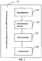
- FIG.1 shows the scheme (10) of the alarm system according to the invention consisting of signal detectors (101), alarm control unit (102), data manager (103) and alarm monitor (104), wherein the signal detector (101) installed in the monitored area and connected to the Alarmkonfrollaji (102) in order to detect smoke, temperature or flammable gas and send these signals to the alarm control unit (102), the alarm control unit (102) being connected to the data manager (103) to detect signals for smoke, temperature or flammable gas collect the displayed detector in real time and send the detected data to the data manager (103), the data manager (103) being connected to the alarm monitor (104) to capture the initial base value at the start of the commissioning and all detected operating data; and to analyze the historical operating data of the individual detector in real time, so that in the event of an alarm being triggered or the detector is performing self-diagnostics or the alarm limit self-adjusts, and the data manager then sends the analysis results to the alarm monitor (104), the alarm monitor (104) receives alarm analysis results from the data manager and displays them on the monitor to monitor the alarm Monitor
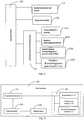
- FIG.2 shows that the data manager (103) shown above further consists of a system setup module (131) which sets up addresses and types of the individual detector; a memory module (132) which receives and stores the initial base value at the start of the commissioning of the detector and operating data of all detectors; a monitoring management module (133) that monitors and analyzes the detected operational data in real time, outputs the alarm signals or the self-diagnostic data or the self-adjustment data about the alarm threshold to the alarm monitor.
- a system setup module 131
- a memory module 132
- a monitoring management module 133 that monitors and analyzes the detected operational data in real time, outputs the alarm signals or the self-diagnostic data or the self-adjustment data about the alarm threshold to the alarm monitor.
- the monitoring management module (133) is comprised of a pre-alarm unit (1331) which, by analyzing the operation data of the individual detector, if the current operational data of a detector is above the initial base value and below the alarm threshold in a certain designated period of time; a detector self-diagnostic unit (1332) which, by analyzing the historical operating data of the single detector in consideration of the detected data at the beginning of the commissioning of the detector, analyzes the changes in the initial base value in real time and triggers an alarm if the current initial base value of the detector is above a is twice as long as the initial base value at the start of the commissioning of the alarm system and shows that the detector is in need of maintenance or checking; an alarm limit self-tuning module (1333) which analyzes the changes in the initial base value in real time by analyzing the historical operating data of the individual detector in consideration of the operational data at the start of the detector and automatically sets the alarm limit value upon change of the initial base value and these changes ; a detector operation trend diagram generating unit 1334 which, upon alarm by
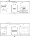
- FIG. 3 shows the diagram (10) of the first embodiment of the alarm system according to the invention, which represents a fire alarm system by means of BCS communication
- the signal detector (101) consists of smoke detector (111), temperature detector (112) and smoke and temperature detector (113)
- Fire alarm controller (121) collects the fire signals in the monitored area in real time by means of BCS communication and sends the detected data to the data manager (103).
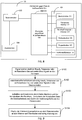
- FIG. 4 shows the diagram (10) of the second embodiment of the alarm system according to the invention, which represents a flammable gas alarm system by BCS communication, wherein the signal detector (101) of Methandetektor (114), Propandetektor (115) and carbon detector (116), and the flammable gas alarm controller (122) collects the fire signals by BCS communication in real time and sends the detected data to the data manager (103).
- the signal detector (101) of Methandetektor (114), Propandetektor (115) and carbon detector (116) and the flammable gas alarm controller (122) collects the fire signals by BCS communication in real time and sends the detected data to the data manager (103).
- FIG. 5 shows the diagram (10) of the third embodiment of alarm system according to the invention, which represents a fire and flammable gas alarm system by means of BCS communication, wherein the signal detector (101) consists of smoke detector (111), temperature detector (112), Rauchu. Temperature detector (113), methane detector (114), propane detector (115) and carbon detector (116), and the alarm controller (123) collects the fire signals in the monitored area in real time by means of BCS communication and sends the detected data to the data manager (103) ,
- the signal detector (101) consists of smoke detector (111), temperature detector (112), Rauchu. Temperature detector (113), methane detector (114), propane detector (115) and carbon detector (116)
- the alarm controller (123) collects the fire signals in the monitored area in real time by means of BCS communication and sends the detected data to the data manager (103) ,
- FIG. 6 Figure 10 shows the diagram (10) of the fourth embodiment of alarm system according to the invention, which represents a fire alarm by means of DCS communication, the signal detector (101) consisting of smoke detector (111), temperature detector (112) and smoke temperature detector (113), and the fire alarm transmitter (121) collects the fire signals in the monitored area in real time by means of DCS communication and sends the detected data to the data manager (103).
- the signal detector (101) consisting of smoke detector (111), temperature detector (112) and smoke temperature detector (113)
- the fire alarm transmitter (121) collects the fire signals in the monitored area in real time by means of DCS communication and sends the detected data to the data manager (103).
- FIG. 7 shows the diagram (10) of the fifth embodiment of alarm system according to the invention, which represents a flammable gas alarm system by means of DCS communication
- the signal detector (101) consists of Methandetektor (114), Propandetektor (115) and carbon detector (116), and the Flammable Gas Alarm Device (122) collects the fire signals in the monitored area in real time by DCS communication and sends the detected data to the Data Manager (103).
- FIG. 8 shows the scheme (10) of the sixth embodiment of alarm system according to the invention, which is an alarm system against fire and flammable gas by DCS communication, the signal detector (101) from smoke detector (111), temperature detector (112), smoke u. Temperature detector (113), methane detector (114), propane detector (115) and carbon detector (116), and the alarm controller (123) collects the fire signals and flammable gas signals in the monitored area in real time by DCS communication and sends the detected data to the Data manager sends.
- Detector self-diagnostic step S1332 used for a real-time analysis of the change of the initial base value by analyzing the historical operation data of the single detector in consideration of the detected data at the start of the start-up of the detector. If the current initial base value of a detector is two times greater than the initial base value at the beginning of commissioning in a certain period of time in real time, this detector triggers an alarm and shows that this detector is in need of maintenance or inspection.
- Alarm limit self-adjustment step S1333 used for a real-time analysis of the change of the initial base value by analyzing the historical operation data of the single detector in consideration of the detected data at the start of the startup. If the initial base value has changed to a reasonable extent, the alarm limit value will automatically adjust accordingly.
- Detector Operation Trend Chart Generation Steps S1334 applied to alarm alarms by searching the data manager for historical data from the alarm detector, and historical data corresponding to the historical trend, to help reduce the number of false alarms.
- the data administrator can represent a PC which receives the initial base value of all the detectors and stores the operating data of the individual detector for years until they have to be exchanged for new ones.
- This PC analyzes in real time the historical operating data of the individual detector in view of the initial base value at the start of commissioning, performs data processing by means of a monitoring management software installed in the data manager and triggers alarm if the address is detected in time, the signals above the initial base value and below the alarm limit and the status is judged abnormal.
- this PC analyzes in real time the historical data of the single detector in view of the initial base value at the start of the detector, discovers in time the change of the initial base value of the single detector, automatically sets the alarm limit and triggers an alarm when the initial base value of the individual detector and shows that the detector in question is in need of maintenance or inspection.
- the initial base value here means the average value of the current data of the product in a specific runtime.
- This average value excluding data above 50% of the alarm limit, may represent the state of the deviation from the guide value of the product, or the adaptation to the given environment may also be interpreted as a deviation from Understand guide value.
- electronic products have deviations, which only take a long time, it is necessary to treat the historical data accordingly, so that a benchmark comparable to today is obtained.
- not all historical data of a certain period of time are used for data processing, they require a specific selection as follows: For example, at all monitored addresses, a current value per minute is available, ie 1440 values per 24 hours.
- This calculation takes place once a day at a fixed time using the monitoring management software installed in the data processor, ie the current initial base value is renewed every 24 hours.
- the data that is over 1/2 of the alarm limit except the one and the remainder of the data is ordered from large to small gives an average value of the middle 1/3 data.
- the initial base value of the current day determined in this way is again combined for averaging with the initial base value 10 days ago, and on the basis of this the most recent initial base value is determined.
- the system calculates once every minute the most recent values for all addresses, as follows: Each time the last 16 data are used and sorted, an average value being calculated from the middle 10 values, thus obtaining the most recent value.
- the monitoring program will give an alarm.
- the system calculates and evaluates each time it receives a new value, i. h., Every minute, a new result comes about.
- the monitoring program will trigger an alarm and show that the detector is in need of maintenance or inspection.
- FIG. 11 and FIG.12 show the workflow of the data manager.
- the system setup Addresses and address types of the detectors are programmed.
- Programming Workflow FIG.11 During operational monitoring, historical data can always be scanned at any time, with several detectors being selected at once and their operating data being able to be compared with one another in the same time period ( FIG.12 ).
- the monitoring program is communicated with the alarm control unit and the current configuration of the control unit can be reported: how many monitored addresses and address types are there and what data results at the particular address. Then these are compared with the programmed data in the system. In the event of a discrepancy, the monitoring personnel are advised to check or confirm.
- the system monitors those addresses that are identical to those programmed in the system. A Timer limits the time to one minute and causes data to be read, reading and storing data at all monitored addresses. Then it is prompted to analyze the current data.
- the previous 16 data are arranged, whereby an average value of the middle 10 values is calculated and so the latest value is available. If the latest value is 10 times continuously 130% greater than the current initial base value and is below the alarm limit value, the monitoring program will trigger an alarm.
- the initial base value of the same day determined in this way is again taken into account for the average value determination with the initial base value 10 days ago, and on the basis of this the most recent initial base value is determined. If the current initial base value is 10 times longer continuous than the current initial base value at the start of commissioning 10 times, the monitoring program will trigger an alarm and show that the detector is in need of maintenance or inspection.
- This invention is not limited to the times or numbers shown, but may be changed through system software according to the monitoring needs. So it is the most flexible.
- This invention both the alarm system and the fire and flammable gas alarm method, allows long-term and permanent monitoring of the output of the single detector, along with a strong CPU processing capacity, allowing the individual detectors to alarm early if their operating data is abnormal the alarm limit has been reached, so that an upstream alarm triggering is possible and an accident risk is nipped in the bud.
- evaluate historical data to see if an alarm is triggered and automatically assess if the detectors are OK, if the data sent is plausible, and if the detectors are in need of care or attention. All this significantly increases the safety factor of the alarm system.
Landscapes
- Engineering & Computer Science (AREA)
- Physics & Mathematics (AREA)
- General Physics & Mathematics (AREA)
- Emergency Management (AREA)
- Chemical & Material Sciences (AREA)
- Business, Economics & Management (AREA)
- General Health & Medical Sciences (AREA)
- Environmental & Geological Engineering (AREA)
- Health & Medical Sciences (AREA)
- Toxicology (AREA)
- Combustion & Propulsion (AREA)
- Computer Security & Cryptography (AREA)
- Analytical Chemistry (AREA)
- Fire Alarms (AREA)
- Alarm Systems (AREA)
- Telephonic Communication Services (AREA)
- Emergency Alarm Devices (AREA)
Claims (8)
- Système d'alarme incendie et de gaz inflammable, le système d'alarme comprenant :au moins un détecteur de signal (101) installé dans des zones à surveiller et employé pour détecter des signaux pour fumée, température ou gaz inflammable ;une unité de contrôle d'alarme (102) ;un administrateur de données (103) ; etun moniteur d'alarme (104) ;le détecteur de signal (101) étant connecté à l'unité de contrôle d'alarme (102) afin d'envoyer les signaux détectés vers l'unité de contrôle d'alarme (102),l'unité de contrôle d'alarme (102) étant utilisé pour collecter en temps réel les signaux reçus par le détecteur de signal (101) et étant connecté à l'administrateur de données (103) afin d'envoyer des signaux vers l'administrateur de données (103),l'administrateur de données (103) étant utilisé pour recevoir et mémoriser une valeur initiale de base au début de la mise en service du détecteur de signal (101) ainsi que des signaux reçus par l'unité de contrôle d'alarme (102) en tant que données historiques d'opération,les données historiques d'opération pouvant être analysées en temps réel pour fournir un résultat d'analyse de sorte qu'une alarme préalable peut être déclenchée ou un autodiagnostic du détecteur de signal (101) peut être effectuée ou une auto-ajustement de la valeur seuil d'alarme peut être effectué, l'administrateur de données (103) étant connecté au moniteur d'alarme (104) afin d'envoyer le résultat d'analyse vers le moniteur d'alarme (104), etle moniteur d'alarme (104) étant utilisé pour visualiser les résultats d'alarme sur un écran ;l'administrateur de données (103) comprenant en outre :un module d'ajustement de système (131) utilisé pour programmer l'adresse et le type du détecteur de signal (101) ; etun module d'administration de surveillance (133) utilisé pour surveiller des signaux en temps réel, pour les analyser et les traiter, le module d'administration de surveillance (133) émettant des données concernant l'alarme préalable ou l'autodiagnostic du détecteur de signal (101) ou l'auto-ajustement de la valeur seuil d'alarme vers le moniteur d'alarme (104) ;caractérisé en ce queen outre le module d'administration de surveillance (133) comprend :une unité d'alarme préalable (1331) utilisée pour analyser les données d'opération du détecteur de signal (101), l'unité d'alarme préalable (1331) étant adaptée pour déclencher de façon prématurée l'alarme préalable lorsque les signaux courants du détecteur de signal (101) excèdent une valeur initiale courante de base pendant une durée définie, mais sont inférieurs à la valeur seuil d'alarme ; le module d'administration de surveillance (133) comprenant en outre :une unité d'autodiagnostic pour détecteur (1332) utilisée pour analyser en temps réel les changements de la valeur initiale de base du détecteur de signal (101), l'unité d'autodiagnostic pour détecteur (1332) étant adaptée pour analyser les données historiques d'opération du détecteur de signal (101) en regard des signaux détectées au début de la mise en service du détecteur de signal (101), et en cas où la valeur initiale courante de base du détecteur de signal (101) diffère de façon permanente de la valeur initiale de base au début de la mise en service, le détecteur de signal (101) étant adapté pour déclencher une alarme et signaler que ce détecteur de signal (101) nécessite entretien ou inspection, etun module d'autodiagnostic pour valeur seuil d'alarme (1333) utilisé pour analyser en temps réel les changements de la valeur initiale de base du détecteur de signal (101), le module d'autodiagnostic pour valeur seuil d'alarme (1333) étant adapté pour analyser les données historiques d'opération d'un détecteur de signal individuel (101) en regard des signaux détectées au début de la mise en service et, en cas la valeur initiale de base a changé dans une échelle significative, le module d'autodiagnostic pour valeur seuil d'alarme (1333) effectuant une auto-ajustage de la valeur seuil d'alarme qui correspond à ce changement,la valeur initiale courante de base étant donnée par une valeur moyenne des signaux du détecteur de signal (101) pendant une durée définie et il y étant représenté, par ladite valeur moyenne, l'état de la divergence à partir de la valeur indicative du détecteur de signal (101), les signaux excédant 50% de la valeur seuil d'alarme n'étant pas pris en compte et ladite valeur moyenne étant calculée à partir du tiers central des données.
- Système d'alarme selon la revendication 1, caractérisé en ce que le module d'administration de surveillance (133) comprend en outre :une unité génératrice d'un diagramme de tendance de l'opération du détecteur (1334), l'unité (1334), en cas d'alarme, effectuant une recherche à travers les données historiques d'opération du détecteur de signal (101) dans le moniteur d'alarme (104) et, basé en cela, effectue la génération d'un diagramme de l'opération du détecteur de signal (101).
- Système d'alarme selon la revendication 1 ou 2, caractérisé en ce que le système d'alarme comprend plusieurs détecteurs de signal (101), les détecteurs de signal (101) comprenant un détecteur de feu et/ou un détecteur de gaz inflammable, le détecteur de feu étant un détecteur de fumée (111) ou un détecteur de température (112) ou un détecteur de fumée et de température (113) et le détecteur de gaz inflammable étant un détecteur de méthane (114), un détecteur de propane (115) ou un détecteur de carbone (116).
- Système d'alarme selon l'une des revendications précédentes 1 ou 2, caractérisé en ce que l'unité de contrôle d'alarme (102) comprend une unité de contrôle d'alarme incendie et/ou une unité de contrôle d'alarme contre gaz inflammable.
- Système d'alarme selon l'une des revendications précédentes 1 ou 2, caractérisé en ce que l'unité de contrôle d'alarme (102) collecte, en temps réel, des signales incendie ou des signales de gaz inflammable au moyen de communication BCS ou de communication DCS.
- Procédé d'alarme contre le feu et gaz inflammable, utilisé pur un système d'alarme selon l'une des revendications 1 à 5, le procédé d'alarme comprenant les étapes suivantes :- des étapes à détecter des signaux au moyen du détecteur de signal (101) pour détecter fumée, température ou gaz inflammable, les signaux détectés étant envoyés vers l'unité de contrôle d'alarme (102) ;- des étapes de contrôle d'alarme au moyen de l'unité de contrôle d'alarme (102) pour connecter en temps réel les signaux reçus par le détecteur de signal (101), lesdits signaux étant envoyés vers l'administrateur de données (103) ;- des étapes d'administration de données par l'administrateur de données (103) dans lesquelles une valeur initiale de base est reçue et mémorisée au début de la mise en service du détecteur de signal (101) et les signaux reçus par l'unité de contrôle d'alarme (102), en tant que données historiques d'opération, sont reçus et mémorisés, les données historiques d'opération étant analysées en temps réel pour fournir des résultats d'analyse de sorte que une alarme préalable ou une autodiagnostic du détecteur de signal ou une auto-ajustement de la valeur seuil d'alarme sont effectuées ; et- des étapes de surveillance d'alarme dans lesquelles les résultats d'analyse envoyés à partir de l'administrateur de données (103) sont visualisés sur un écran d'alarme (104) ; les étapes d'administration de données comprenant en outre :- une étape de configuration de programme dans laquelle l'adresse et le type du détecteur de signal (101) est programmé ;- des étapes de mémorisation dans lesquelles les valeurs initiales de base de l'au moins un détecteur de signal (101) au début de la mise en service et les signaux de l'au moins un détecteur de signal (101) sont reçus et mémorisés ; et- des étapes d'administration de surveillance dans lesquelles les signaux sont analysés en temps réel et une signal préalable d'alarme ou un signal d'autodiagnostic du détecteur ou un signal d'auto-ajustement du valeur seuil d'alarme sont envoyés vers le moniteur d'alarme ;les étapes d'administration de surveillance comprenant en outre :- des étapes d'alarme préalable dans lesquelles une alarme préalable est déclenché par analyse des signaux du détecteur individuel de signal (101) lorsque les signaux courants de l'au moins un détecteur de signal (101) excèdent une valeur initiale courante de base pendant une durée définie mais sont inférieurs à la valeur seuil d'alarme ;- des étapes d'autodiagnostic pour le détecteur dans lesquelles les changements de la valeur initiale de base du détecteur de signal (101) sont analysés, les données historiques d'opération du détecteur de signal (101) étant analysés par l'unité d'autodiagnostic pour détecteur (1332) en regard des signaux détectées au début de la mise en service du détecteur de signal (101) et, en cas où la valeur initiale courante de base du détecteur de signal (101) diffère de façon permanente de la valeur initiale de base au début de la mise en service pendant une durée définie, une alarme étant déclenchée ou signalée par le détecteur de signal (101) de façon à signaler que ce détecteur de signal (101) nécessite entretien ou inspection ;- des étapes d'auto-ajustement de la valeur seuil dans lesquelles les données historiques d'opération du détecteur individuel de signal (101) sont analysés en regard des signaux détectées au début de la mise en service du module d'autodiagnostic pour valeur seuil d'alarme (1333), la valeur initiale de base étant analysée en temps réel et l'auto-ajustement de la valeur seuil d'alarme étant effectué par le module d'autodiagnostic pour valeur seuil d'alarme (1333) en correspondance avec les changements de la valeur initiale de base dans une échelle significative ;la valeur initiale courante de base étant donnée par la valeur moyenne des données courantes et il y étant représenté, par ladite valeur moyenne, l'état de la divergence à partir de la valeur indicative du détecteur de signal (101), les signaux excédant 50% de la valeur seuil d'alarme n'étant pas pris en compte et ladite valeur moyenne étant calculée à partir du tiers central des données.
- Procédé d'alarme selon la revendication 6, caractérisé en ce qu'en outre les étapes de surveillance comprennent :l'administrateur de données (103) effectue, en cas d'alarme, une recherche à travers les données historiques d'opération du détecteur de signal (101) et, basé en cela, effectue la génération d'un diagramme indiquant la tendance historique.
- Procédé d'alarme selon l'une des revendications 6 ou 7, caractérisé en ce que dans les étapes de contrôle d'alarme, des signales incendie ou des signales de gaz inflammable sont collectés en temps réel dans les zones surveillées par l'unité de contrôle d'alarme (102) au moyen de communication BCS ou de communication DCS.
Priority Applications (1)
| Application Number | Priority Date | Filing Date | Title |
|---|---|---|---|
| PL10829430T PL2500882T3 (pl) | 2009-11-10 | 2010-06-21 | Układ alarmujący o pożarze i zapłonie gazu oraz odnośny sposób |
Applications Claiming Priority (2)
| Application Number | Priority Date | Filing Date | Title |
|---|---|---|---|
| CN 200910237391 CN101719299B (zh) | 2009-11-10 | 2009-11-10 | 一种火灾、可燃气体报警系统及方法 |
| PCT/CN2010/000900 WO2011057465A1 (fr) | 2009-11-10 | 2010-06-21 | Système d'alarme incendie et de gaz inflammable et procédé associé |
Publications (3)
| Publication Number | Publication Date |
|---|---|
| EP2500882A1 EP2500882A1 (fr) | 2012-09-19 |
| EP2500882A4 EP2500882A4 (fr) | 2013-07-10 |
| EP2500882B1 true EP2500882B1 (fr) | 2018-02-28 |
Family
ID=42433867
Family Applications (1)
| Application Number | Title | Priority Date | Filing Date |
|---|---|---|---|
| EP10829430.7A Not-in-force EP2500882B1 (fr) | 2009-11-10 | 2010-06-21 | Système d'alarme incendie et de gaz inflammable et procédé associé |
Country Status (7)
| Country | Link |
|---|---|
| US (1) | US8957782B2 (fr) |
| EP (1) | EP2500882B1 (fr) |
| JP (1) | JP5335144B2 (fr) |
| CN (1) | CN101719299B (fr) |
| PL (1) | PL2500882T3 (fr) |
| RU (1) | RU2517309C2 (fr) |
| WO (1) | WO2011057465A1 (fr) |
Cited By (1)
| Publication number | Priority date | Publication date | Assignee | Title |
|---|---|---|---|---|
| EP4600929A1 (fr) | 2024-02-12 | 2025-08-13 | Robert Bosch GmbH | Procédé de vérification de préalarme agencée pour détecter une prévention d'alarme |
Families Citing this family (80)
| Publication number | Priority date | Publication date | Assignee | Title |
|---|---|---|---|---|
| CN101719299B (zh) | 2009-11-10 | 2012-03-28 | 天津市浦海新技术有限公司 | 一种火灾、可燃气体报警系统及方法 |
| CN102455335A (zh) * | 2010-10-18 | 2012-05-16 | 淮南矿业(集团)有限责任公司 | 自动检测气体浓度异常的方法和检测系统 |
| CN102637337B (zh) * | 2012-04-23 | 2015-08-05 | 宁波市科技园区佳柏电子有限公司 | 一种自适应烟雾报警器的报警方法 |
| CN102682562A (zh) * | 2012-05-29 | 2012-09-19 | 公安部上海消防研究所 | 一种在线式火灾烟气探测装置 |
| CN102737473A (zh) * | 2012-06-20 | 2012-10-17 | 天津市浦海新技术有限公司 | 具有通讯功能的火灾、可燃气体报警系统及其实现方法 |
| CN102903210A (zh) * | 2012-09-20 | 2013-01-30 | 天津市浦海新技术有限公司 | 一种燃气安全检测及预测报警系统 |
| CN102881107A (zh) * | 2012-09-26 | 2013-01-16 | 金海新源电气江苏有限公司 | 分布式光纤温度传感器的报警阈值自适应方法 |
| CN102914328B (zh) * | 2012-10-23 | 2014-09-17 | 深圳市计通智能技术有限公司 | 一种计算机机房温湿度监控系统报警阀值自动调整方法 |
| EP2775464B1 (fr) * | 2013-03-06 | 2018-01-17 | Siemens Schweiz AG | Alarme dotée d'un capteur de rayonnement thermique sans contact pour déterminer une température ambiante |
| CN105122633B (zh) | 2013-04-09 | 2019-04-05 | 热成像雷达有限责任公司 | 步进电机控制系统及方法 |
| WO2014169066A1 (fr) * | 2013-04-09 | 2014-10-16 | Thermal Imaging Radar, LLC | Système de détection de feu |
| KR102248161B1 (ko) | 2013-08-09 | 2021-05-04 | 써멀 이미징 레이다 엘엘씨 | 복수의 가상 장치를 이용하여 열 이미지 데이터를 분석하기 위한 방법들 및 깊이 값들을 이미지 픽셀들에 상관시키기 위한 방법들 |
| CN103440726B (zh) * | 2013-09-03 | 2016-01-20 | 苏州太谷电力股份有限公司 | 电气火灾预警信息处理方法和系统 |
| US9990842B2 (en) | 2014-06-03 | 2018-06-05 | Carrier Corporation | Learning alarms for nuisance and false alarm reduction |
| CN104574849A (zh) * | 2015-01-14 | 2015-04-29 | 深圳市欧瑞博电子有限公司 | 一种燃气报警装置的阈值设置方法 |
| CN104658160A (zh) * | 2015-03-13 | 2015-05-27 | 深圳市金益能达科技有限公司 | 一种多功能火灾侦测报警器及其侦测方法 |
| WO2016160794A1 (fr) | 2015-03-31 | 2016-10-06 | Thermal Imaging Radar, LLC | Réglage de différentes sensibilités de modèle d'arrière-plan par des régions définies par l'utilisateur et des filtres d'arrière-plan |
| CN105279917A (zh) * | 2015-09-25 | 2016-01-27 | 卡斯柯信号有限公司 | 一种基于旋转门算法的实时预警方法 |
| CN105206005A (zh) * | 2015-10-15 | 2015-12-30 | 成都信息工程大学 | 一种集成预警装置 |
| CN105243778A (zh) * | 2015-11-11 | 2016-01-13 | 江苏银佳企业集团有限公司 | 一种基于网络化的智能消防报警对讲联动系统 |
| US10211999B2 (en) * | 2016-02-09 | 2019-02-19 | Bruce A Pelton | Integrated building management sensor system |
| CN106530578B (zh) * | 2016-09-19 | 2018-11-20 | 上海波汇科技股份有限公司 | 一种感温火灾报警系统的阈值处理方法 |
| US10754964B2 (en) | 2016-11-01 | 2020-08-25 | Bruce A Pelton | Integrated building management sensor system |
| CN106408886A (zh) * | 2016-12-16 | 2017-02-15 | 上海腾盛智能安全科技股份有限公司 | 一种可燃气体探测系统 |
| CN106843247A (zh) * | 2017-01-17 | 2017-06-13 | 广东容祺智能科技有限公司 | 一种基于互联网的环境检测巡检无人机系统 |
| CN106710156A (zh) * | 2017-03-16 | 2017-05-24 | 亿信标准认证集团有限公司 | 存储库的可燃气体超标检测报警系统 |
| CN107204100A (zh) * | 2017-06-06 | 2017-09-26 | 榆林学院 | 一种基于石油钻井平台的硫化氢报警系统及方法 |
| CN107316430A (zh) * | 2017-06-22 | 2017-11-03 | 封宇 | 配电房开闭所安全预警系统 |
| US10574886B2 (en) | 2017-11-02 | 2020-02-25 | Thermal Imaging Radar, LLC | Generating panoramic video for video management systems |
| CN108335467B (zh) * | 2018-01-05 | 2019-07-23 | 东华大学 | 一种基于突变点探测的火灾在线预警与快速分析方法 |
| CN108469274A (zh) * | 2018-03-28 | 2018-08-31 | 北京经纬恒润科技有限公司 | 一种工况识别及模式切换的方法及装置 |
| CN108416987A (zh) * | 2018-04-20 | 2018-08-17 | 华科物联有限公司 | 九小场所智慧消防物联网系统 |
| CN110580796A (zh) * | 2018-06-11 | 2019-12-17 | 北京众和清扬科技有限公司 | 一种智能安全暨灾害预警系统及方法 |
| CN115586226A (zh) * | 2018-07-11 | 2023-01-10 | 上海兆莹自控设备有限公司 | 现场气体双传感器检测系统及其控制方法 |
| CN108932781B (zh) * | 2018-07-26 | 2021-06-11 | 天津中兴智联科技有限公司 | 一种门禁管理场景中的rssi阈值自学习方法 |
| CN109186665A (zh) * | 2018-08-10 | 2019-01-11 | 杭州天宽科技有限公司 | 一种可连接云端自动推送报警信息的检测报警器及其工作方法 |
| CN109598911B (zh) * | 2018-08-23 | 2021-09-28 | 浙江宇视科技有限公司 | 预警方法、装置及计算机可读存储介质 |
| CN110570620A (zh) * | 2019-07-30 | 2019-12-13 | 大唐东营发电有限公司 | 一种火电厂环境烟气监测预警防火系统 |
| CN110726680A (zh) * | 2019-09-27 | 2020-01-24 | 国网山西省电力公司太原供电公司 | 一种电缆井火灾预警方法 |
| CN110728820B (zh) * | 2019-10-21 | 2021-07-13 | 中车大连机车研究所有限公司 | 一种机车多参数复合火灾报警控制方法及系统 |
| US11601605B2 (en) | 2019-11-22 | 2023-03-07 | Thermal Imaging Radar, LLC | Thermal imaging camera device |
| CN110958309B (zh) * | 2019-11-25 | 2022-03-15 | 河北泽宏科技股份有限公司 | 基于智慧城市的信息化应急系统 |
| US11145187B2 (en) | 2019-12-30 | 2021-10-12 | Climax Technology Co., Ltd. | Integrated fire alarm method and system |
| EP3848917B1 (fr) * | 2020-01-09 | 2024-04-17 | Climax Technology Co., Ltd. | Système et procédé d'alarme incendie intégrés |
| CN111722612A (zh) * | 2020-05-21 | 2020-09-29 | 上海四量电子科技有限公司 | 一种电力少油监控预测系统 |
| CN111724562B (zh) * | 2020-06-05 | 2021-11-16 | 珠海格力电器股份有限公司 | 一种烟雾报警器及其修正方法 |
| CN111882800B (zh) * | 2020-06-20 | 2022-08-30 | 杭州后博科技有限公司 | 一种基于多维度数据联动的消防预警方法及系统 |
| CN113932256B (zh) * | 2020-06-29 | 2025-07-18 | 青岛海尔智能技术研发有限公司 | 一种用于燃气灶的故障检测方法及燃气灶 |
| PL4176422T3 (pl) | 2020-07-03 | 2025-06-23 | Siemens Schweiz Ag | Sposób automatycznej kontroli systemu sygnalizacji pożarowej |
| CN111769644B (zh) * | 2020-07-08 | 2021-10-15 | 广州百畅信息科技有限公司 | 一种基于电网安全的监控系统 |
| CN112017399A (zh) * | 2020-08-27 | 2020-12-01 | 广东电网有限责任公司 | 一种输配电线路导线侧空域主动控制器 |
| CN111999441A (zh) * | 2020-08-28 | 2020-11-27 | 福建美营自动化科技有限公司 | 多通道极低浓度易燃易爆气体快速探测仪及气体甄别方法 |
| CN112017389B (zh) * | 2020-09-14 | 2022-08-09 | 杭州海康消防科技有限公司 | 火灾探测器及火灾探测方法 |
| CN113012420A (zh) * | 2020-09-27 | 2021-06-22 | 张家港市恒拓科技服务合伙企业(有限合伙) | 基于能源互联网的电气预警智慧用电方法、系统及介质 |
| CN112750270B (zh) * | 2020-12-29 | 2023-05-12 | 深圳市利拓光电有限公司 | 基于激光传感器的烟雾报警方法、装置及设备 |
| CN112820062B (zh) * | 2021-01-19 | 2022-05-03 | 武汉拓宝科技股份有限公司 | 一种火灾发生概率预测方法及系统 |
| CN112907111A (zh) * | 2021-03-18 | 2021-06-04 | 应急管理部沈阳消防研究所 | 一种基于物联网技术的监控数据智能采集及分析方法 |
| CN113192282A (zh) * | 2021-04-16 | 2021-07-30 | 南京玄甲物联科技有限公司 | 一种基于物联网技术的火灾预警系统 |
| CN113219139A (zh) * | 2021-05-25 | 2021-08-06 | 鑫翊(上海)实业有限公司 | 有害气体检测系统、检测方法及装置 |
| CN113341774B (zh) * | 2021-05-31 | 2021-12-28 | 浙江锐博科技工程有限公司 | 大型公共建筑能耗监测系统 |
| CN114046819B (zh) * | 2021-09-28 | 2024-09-24 | 河北邯峰发电有限责任公司 | 一种筒仓安全监测系统和装置 |
| CN114067517A (zh) * | 2021-10-26 | 2022-02-18 | 江西省力安智能科技有限公司 | 一种独立式烟感装置及其运行控制方法 |
| CN114115070A (zh) * | 2021-12-08 | 2022-03-01 | 孙唯一 | 危化品库房可视化监控系统 |
| CN114463954B (zh) * | 2022-04-13 | 2022-06-21 | 尼特智能科技股份有限公司 | 一种基于物联网的可燃气体监测预警系统及方法 |
| CN114722720B (zh) * | 2022-04-22 | 2025-03-14 | 深圳市铠湾安全技术有限公司 | 一种捕捉可燃气体探测器数值变化的智能预警方法 |
| CN115116194A (zh) * | 2022-05-30 | 2022-09-27 | 国能神福(石狮)发电有限公司 | 燃料系统智能监控预警系统 |
| CN115100824A (zh) * | 2022-07-12 | 2022-09-23 | 佛山市壹品慧电气有限公司 | 一种增量式燃气检测方法及其安全燃气设备 |
| CN115206063A (zh) * | 2022-07-21 | 2022-10-18 | 因士(上海)科技有限公司 | 一种油气泄漏可视化监测系统及方法 |
| CN115457720B (zh) * | 2022-07-21 | 2024-07-16 | 清华大学 | 基于探测信号相关性的实时多探测器火灾探测方法及装置 |
| CN115792133B (zh) * | 2022-12-23 | 2023-11-07 | 天津新亚精诚科技有限公司 | 一种基于可燃气体监测的消防安全分析方法及系统 |
| CN116153032A (zh) * | 2022-12-29 | 2023-05-23 | 东莞三江港口储罐有限公司 | 可燃有毒气体监控系统 |
| JP7792360B2 (ja) * | 2023-01-31 | 2025-12-25 | 能美防災株式会社 | 機器操作盤 |
| CN116798204B (zh) * | 2023-08-14 | 2023-11-03 | 成都数智创新精益科技有限公司 | 一种安防方法、装置、设备及存储介质 |
| CN117523769B (zh) * | 2023-10-31 | 2024-12-13 | 浙江上青元电力科技有限公司 | 一种极早期火灾监测系统 |
| CN118522112B (zh) * | 2024-05-14 | 2025-11-21 | 蚌埠依爱消防电子有限责任公司 | 一种提高感烟火灾探测器抗积灰性能的方法和系统 |
| CN118736777A (zh) * | 2024-06-05 | 2024-10-01 | 南通东来冶金装备有限公司 | 一种基于大数据分析的燃气设备预警方法及系统 |
| CN118887769B (zh) * | 2024-09-28 | 2025-02-21 | 英迈斯(福建)信息技术有限公司 | 一种智慧园区节能式消防报警器 |
| CN119360559A (zh) * | 2024-10-24 | 2025-01-24 | 安徽鸿凌科技股份有限公司 | 燃气报警器及其双向联动控制方法 |
| CN119353054B (zh) * | 2024-12-20 | 2025-03-14 | 安徽中益新材料科技股份有限公司 | 一种用于隧道火灾工况的负离子浓度测量与控制系统 |
| CN120260202B (zh) * | 2025-04-16 | 2025-09-26 | 国网辽宁省电力有限公司沈阳供电公司 | 一种基于封闭空间的电缆接头防火报警系统及方法 |
Family Cites Families (32)
| Publication number | Priority date | Publication date | Assignee | Title |
|---|---|---|---|---|
| US5148148A (en) * | 1989-12-28 | 1992-09-15 | Hochiki Kabushiki Kaisha | Radio alarm system |
| US5376924A (en) | 1991-09-26 | 1994-12-27 | Hochiki Corporation | Fire sensor |
| JP3213372B2 (ja) * | 1992-04-23 | 2001-10-02 | 松下電工株式会社 | 火災警報システム |
| DE4143092A1 (de) * | 1991-12-27 | 1993-07-01 | Bayer Ag | Gasspurenmesssystem |
| DE4302367A1 (de) * | 1993-01-28 | 1994-08-04 | Rwe Energie Ag | System zur indirekten Ermittlung kritischer Zustände von zustandsabhängig Gase entwickelnden Stoffen, Anlagenteilen ect. |
| US6107925A (en) * | 1993-06-14 | 2000-08-22 | Edwards Systems Technology, Inc. | Method for dynamically adjusting criteria for detecting fire through smoke concentration |
| JPH1063965A (ja) * | 1996-08-27 | 1998-03-06 | Nohmi Bosai Ltd | 火災報知設備 |
| CN1121666C (zh) * | 1998-06-20 | 2003-09-17 | 蚌埠依爱消防电子有限责任公司 | 对报警控制器上模拟量探测器进行动态监测的方法 |
| US6624750B1 (en) * | 1998-10-06 | 2003-09-23 | Interlogix, Inc. | Wireless home fire and security alarm system |
| US6252510B1 (en) * | 1998-10-14 | 2001-06-26 | Bud Dungan | Apparatus and method for wireless gas monitoring |
| US6960987B2 (en) * | 2001-09-21 | 2005-11-01 | Hochiki Corporation | Fire alarm system, fire sensor, fire receiver, and repeater |
| JP4066761B2 (ja) * | 2001-11-27 | 2008-03-26 | 松下電工株式会社 | 火災警報システム |
| US7080544B2 (en) * | 2002-08-23 | 2006-07-25 | Firemaster Oilfield Services Inc. | Apparatus system and method for gas well site monitoring |
| JP4033749B2 (ja) * | 2002-10-03 | 2008-01-16 | 大阪瓦斯株式会社 | 異常判定方法,および電子機器 |
| RU2258260C2 (ru) * | 2003-06-30 | 2005-08-10 | Закрытое акционерное общество "Телесофт-Сервис" | Дымовой извещатель |
| DE10330368B4 (de) * | 2003-06-30 | 2008-11-27 | Pronet Gmbh | Verfahren und Anordnung zur Identifizierung und/oder Differenzierung von durch Sensoren angezeigten Stoffen in Gasgemischen sowie ein entsprechendes Computerprogramm und ein entsprechendes computerlesbares Speichermedium |
| JP4344269B2 (ja) * | 2004-03-30 | 2009-10-14 | 能美防災株式会社 | 火災感知器およびその状態情報取得システム |
| US7623028B2 (en) * | 2004-05-27 | 2009-11-24 | Lawrence Kates | System and method for high-sensitivity sensor |
| US20060176167A1 (en) * | 2005-01-25 | 2006-08-10 | Laser Shield Systems, Inc. | Apparatus, system, and method for alarm systems |
| US20060267758A1 (en) * | 2005-02-18 | 2006-11-30 | Barth R T | System and method for detection of a variety of alarm conditions |
| JP2006277138A (ja) * | 2005-03-28 | 2006-10-12 | Tokyo Gas Co Ltd | 火災警報器又は火災検知装置 |
| CN2785052Y (zh) * | 2005-04-07 | 2006-05-31 | 华南理工大学 | 一种地铁火灾智能监测预警预报装置 |
| JP4679225B2 (ja) * | 2005-04-28 | 2011-04-27 | 新コスモス電機株式会社 | 火災警報器および煙センサの交換時期演算方法 |
| US7528711B2 (en) * | 2005-12-19 | 2009-05-05 | Lawrence Kates | Portable monitoring unit |
| US7535687B2 (en) * | 2006-04-13 | 2009-05-19 | Ge Security, Inc. | Alarm system sensor topology apparatus and method |
| CN1963878A (zh) * | 2006-11-27 | 2007-05-16 | 华南理工大学 | 高层建筑火灾智能监测预警预报装置 |
| CN101251942B (zh) * | 2008-03-14 | 2010-04-21 | 华南理工大学 | 地下空间火灾智能检测预警预报方法及装置 |
| US8970365B2 (en) * | 2008-12-30 | 2015-03-03 | Oneevent Technologies, Inc. | Evacuation system |
| CN101482531B (zh) * | 2009-01-10 | 2012-05-16 | 大连理工大学 | 一种用于可燃气体探测器的基线漂移自适应补偿探测方法 |
| RU82270U1 (ru) * | 2009-01-21 | 2009-04-20 | Андрей Викторович Демидюк | Шахтная система мониторинга, оповещения и определения местоположения горнорабочих |
| CN101533549B (zh) * | 2009-04-17 | 2010-08-18 | 宁波振东光电有限公司 | 一种采用分布式光纤温度传感器系统进行火灾报警的方法 |
| CN101719299B (zh) * | 2009-11-10 | 2012-03-28 | 天津市浦海新技术有限公司 | 一种火灾、可燃气体报警系统及方法 |
-
2009
- 2009-11-10 CN CN 200910237391 patent/CN101719299B/zh not_active Expired - Fee Related
-
2010
- 2010-06-21 US US13/508,808 patent/US8957782B2/en active Active
- 2010-06-21 WO PCT/CN2010/000900 patent/WO2011057465A1/fr not_active Ceased
- 2010-06-21 PL PL10829430T patent/PL2500882T3/pl unknown
- 2010-06-21 JP JP2012527178A patent/JP5335144B2/ja not_active Expired - Fee Related
- 2010-06-21 EP EP10829430.7A patent/EP2500882B1/fr not_active Not-in-force
- 2010-06-21 RU RU2012121838/08A patent/RU2517309C2/ru active
Non-Patent Citations (1)
| Title |
|---|
| None * |
Cited By (1)
| Publication number | Priority date | Publication date | Assignee | Title |
|---|---|---|---|---|
| EP4600929A1 (fr) | 2024-02-12 | 2025-08-13 | Robert Bosch GmbH | Procédé de vérification de préalarme agencée pour détecter une prévention d'alarme |
Also Published As
| Publication number | Publication date |
|---|---|
| JP2013504102A (ja) | 2013-02-04 |
| EP2500882A4 (fr) | 2013-07-10 |
| US8957782B2 (en) | 2015-02-17 |
| RU2517309C2 (ru) | 2014-05-27 |
| US20120293334A1 (en) | 2012-11-22 |
| JP5335144B2 (ja) | 2013-11-06 |
| CN101719299B (zh) | 2012-03-28 |
| EP2500882A1 (fr) | 2012-09-19 |
| CN101719299A (zh) | 2010-06-02 |
| WO2011057465A1 (fr) | 2011-05-19 |
| RU2012121838A (ru) | 2013-12-20 |
| PL2500882T3 (pl) | 2018-10-31 |
Similar Documents
| Publication | Publication Date | Title |
|---|---|---|
| EP2500882B1 (fr) | Système d'alarme incendie et de gaz inflammable et procédé associé | |
| EP2771570B1 (fr) | Procédé de commande d'une éolienne | |
| DE2622120A1 (de) | Verfahren und vorrichtung zur automatischen ueberwachung von anlagen | |
| DE112018001684T5 (de) | Indikatorerfassungssystem und Indikatorerfassungsverfahren | |
| WO2005048207A1 (fr) | Procede et dispositif pour reconnaitre et localiser un incendie | |
| DE102018107233A1 (de) | Verfahren zur automatischen Prozessüberwachung und Prozessdiagnose eines stückbasierten Prozesses (batch-Fertigung), insbesondere eines Spritzgießprozesses und eine den Prozess durchführende Maschine oder ein den Prozess durchführender Maschinenpark | |
| CN112738236A (zh) | 大厦端智慧消防管理系统及方法 | |
| EP2898490B1 (fr) | Installation de détection d'incendie et réseau de détection d'incendie comportant une pluralité d'installations de détection d'incendie | |
| EP2169221A2 (fr) | Procédé de surveillance d'un engrenage d'éolienne | |
| EP2898491B1 (fr) | Dispositif d'évaluation pour un système de surveillance ainsi que système de surveillance doté du dispositif d'évaluation | |
| DE102008012097B4 (de) | Überwachungseinrichtung für den Betrieb von Schaltschrankgeräten | |
| DE102021105014A1 (de) | Verfahren zur Auswertung von Daten wenigstens eines mobilen und eines stationären Gasmessgeräts sowie System zur Überwachung mindestens einer Gaskonzentration | |
| DE102018204734A1 (de) | Sicherheitsinstrumentierte Steuervorrichtung und entsprechendes Verfahren, und Sicherheitsinstrumentiertes System | |
| DE102017131241B4 (de) | Überwachungsverfahren für eine Windkraftanlage, zugehörige Überwachungsvorrichtung sowie Windkraftanlage mit Überwachungsvorrichtung | |
| EP3967002B1 (fr) | Dispositif de service pour un système de protection contre l'incendie, système de protection contre l'incendie correspondant, système de fonctionnement d'un système de protection contre l'incendie et ??procédé associé | |
| DE102018218655A1 (de) | Brandmelder | |
| EP4226494A1 (fr) | Procédé de surveillance d'un ou de plusieurs entraînements électriques d'un système électromécanique | |
| EP4411327A1 (fr) | Procédé de surveillance d'une installation de réglage et de mesure de pression de gaz | |
| DE20215640U1 (de) | Vorrichtung zum Prüfen von Brandmeldern und Brand-Rauchschutzklappen | |
| EP3772048A1 (fr) | Enveloppe à surpression | |
| DE102005051452A1 (de) | Verfahren und Vorrichtung zur automatischen Ermittlung von Wartungszeitpunkten | |
| EP1714240A1 (fr) | Systeme et procede d'analyse automatisee des risques et/ou d'optimisation automatisee de la duree de service d'installations techniques | |
| WO2013104419A1 (fr) | Aide à la prévention d'incidents dans une installation industrielle au moyen d'un modèle de défaillance | |
| DE19746272A1 (de) | Vorrichtung zur Vermessung mechanisch belasteter Bauteile | |
| EP1598717B1 (fr) | Procédé de surveillance d'une pluralité des installations de gaz |
Legal Events
| Date | Code | Title | Description |
|---|---|---|---|
| PUAI | Public reference made under article 153(3) epc to a published international application that has entered the european phase |
Free format text: ORIGINAL CODE: 0009012 |
|
| 17P | Request for examination filed |
Effective date: 20120611 |
|
| AK | Designated contracting states |
Kind code of ref document: A1 Designated state(s): AL AT BE BG CH CY CZ DE DK EE ES FI FR GB GR HR HU IE IS IT LI LT LU LV MC MK MT NL NO PL PT RO SE SI SK SM TR |
|
| DAX | Request for extension of the european patent (deleted) | ||
| A4 | Supplementary search report drawn up and despatched |
Effective date: 20130606 |
|
| RIC1 | Information provided on ipc code assigned before grant |
Ipc: G08B 21/16 20060101ALI20130531BHEP Ipc: G08B 17/10 20060101AFI20130531BHEP Ipc: G08B 29/00 20060101ALI20130531BHEP Ipc: G08B 17/117 20060101ALI20130531BHEP |
|
| RIC1 | Information provided on ipc code assigned before grant |
Ipc: G08B 17/117 20060101ALI20131112BHEP Ipc: G08B 29/00 20060101ALI20131112BHEP Ipc: G08B 17/10 20060101AFI20131112BHEP Ipc: G08B 21/16 20060101ALI20131112BHEP |
|
| RIC1 | Information provided on ipc code assigned before grant |
Ipc: G08B 29/00 20060101ALI20150430BHEP Ipc: G08B 17/00 20060101ALI20150430BHEP Ipc: G08B 29/26 20060101ALI20150430BHEP Ipc: G08B 17/10 20060101AFI20150430BHEP Ipc: G08B 21/16 20060101ALI20150430BHEP Ipc: G08B 17/117 20060101ALI20150430BHEP |
|
| 17Q | First examination report despatched |
Effective date: 20150522 |
|
| GRAP | Despatch of communication of intention to grant a patent |
Free format text: ORIGINAL CODE: EPIDOSNIGR1 |
|
| INTG | Intention to grant announced |
Effective date: 20171012 |
|
| GRAS | Grant fee paid |
Free format text: ORIGINAL CODE: EPIDOSNIGR3 |
|
| GRAA | (expected) grant |
Free format text: ORIGINAL CODE: 0009210 |
|
| AK | Designated contracting states |
Kind code of ref document: B1 Designated state(s): AL AT BE BG CH CY CZ DE DK EE ES FI FR GB GR HR HU IE IS IT LI LT LU LV MC MK MT NL NO PL PT RO SE SI SK SM TR |
|
| REG | Reference to a national code |
Ref country code: GB Ref legal event code: FG4D Ref country code: CH Ref legal event code: EP |
|
| REG | Reference to a national code |
Ref country code: AT Ref legal event code: REF Ref document number: 974936 Country of ref document: AT Kind code of ref document: T Effective date: 20180315 |
|
| REG | Reference to a national code |
Ref country code: IE Ref legal event code: FG4D Free format text: LANGUAGE OF EP DOCUMENT: GERMAN |
|
| REG | Reference to a national code |
Ref country code: DE Ref legal event code: R096 Ref document number: 502010014712 Country of ref document: DE |
|
| REG | Reference to a national code |
Ref country code: RO Ref legal event code: EPE |
|
| RAP2 | Party data changed (patent owner data changed or rights of a patent transferred) |
Owner name: TIANJIN PUHAI NEW TECHNOLOGY CO., LTD. |
|
| REG | Reference to a national code |
Ref country code: NL Ref legal event code: MP Effective date: 20180228 |
|
| REG | Reference to a national code |
Ref country code: LT Ref legal event code: MG4D |
|
| PG25 | Lapsed in a contracting state [announced via postgrant information from national office to epo] |
Ref country code: NO Free format text: LAPSE BECAUSE OF FAILURE TO SUBMIT A TRANSLATION OF THE DESCRIPTION OR TO PAY THE FEE WITHIN THE PRESCRIBED TIME-LIMIT Effective date: 20180528 Ref country code: FI Free format text: LAPSE BECAUSE OF FAILURE TO SUBMIT A TRANSLATION OF THE DESCRIPTION OR TO PAY THE FEE WITHIN THE PRESCRIBED TIME-LIMIT Effective date: 20180228 Ref country code: LT Free format text: LAPSE BECAUSE OF FAILURE TO SUBMIT A TRANSLATION OF THE DESCRIPTION OR TO PAY THE FEE WITHIN THE PRESCRIBED TIME-LIMIT Effective date: 20180228 Ref country code: NL Free format text: LAPSE BECAUSE OF FAILURE TO SUBMIT A TRANSLATION OF THE DESCRIPTION OR TO PAY THE FEE WITHIN THE PRESCRIBED TIME-LIMIT Effective date: 20180228 Ref country code: CY Free format text: LAPSE BECAUSE OF FAILURE TO SUBMIT A TRANSLATION OF THE DESCRIPTION OR TO PAY THE FEE WITHIN THE PRESCRIBED TIME-LIMIT Effective date: 20180228 Ref country code: ES Free format text: LAPSE BECAUSE OF FAILURE TO SUBMIT A TRANSLATION OF THE DESCRIPTION OR TO PAY THE FEE WITHIN THE PRESCRIBED TIME-LIMIT Effective date: 20180228 Ref country code: HR Free format text: LAPSE BECAUSE OF FAILURE TO SUBMIT A TRANSLATION OF THE DESCRIPTION OR TO PAY THE FEE WITHIN THE PRESCRIBED TIME-LIMIT Effective date: 20180228 |
|
| PG25 | Lapsed in a contracting state [announced via postgrant information from national office to epo] |
Ref country code: BG Free format text: LAPSE BECAUSE OF FAILURE TO SUBMIT A TRANSLATION OF THE DESCRIPTION OR TO PAY THE FEE WITHIN THE PRESCRIBED TIME-LIMIT Effective date: 20180528 Ref country code: SE Free format text: LAPSE BECAUSE OF FAILURE TO SUBMIT A TRANSLATION OF THE DESCRIPTION OR TO PAY THE FEE WITHIN THE PRESCRIBED TIME-LIMIT Effective date: 20180228 Ref country code: LV Free format text: LAPSE BECAUSE OF FAILURE TO SUBMIT A TRANSLATION OF THE DESCRIPTION OR TO PAY THE FEE WITHIN THE PRESCRIBED TIME-LIMIT Effective date: 20180228 Ref country code: GR Free format text: LAPSE BECAUSE OF FAILURE TO SUBMIT A TRANSLATION OF THE DESCRIPTION OR TO PAY THE FEE WITHIN THE PRESCRIBED TIME-LIMIT Effective date: 20180529 |
|
| PG25 | Lapsed in a contracting state [announced via postgrant information from national office to epo] |
Ref country code: MT Free format text: LAPSE BECAUSE OF FAILURE TO SUBMIT A TRANSLATION OF THE DESCRIPTION OR TO PAY THE FEE WITHIN THE PRESCRIBED TIME-LIMIT Effective date: 20180228 |
|
| PG25 | Lapsed in a contracting state [announced via postgrant information from national office to epo] |
Ref country code: EE Free format text: LAPSE BECAUSE OF FAILURE TO SUBMIT A TRANSLATION OF THE DESCRIPTION OR TO PAY THE FEE WITHIN THE PRESCRIBED TIME-LIMIT Effective date: 20180228 Ref country code: IT Free format text: LAPSE BECAUSE OF FAILURE TO SUBMIT A TRANSLATION OF THE DESCRIPTION OR TO PAY THE FEE WITHIN THE PRESCRIBED TIME-LIMIT Effective date: 20180228 Ref country code: AL Free format text: LAPSE BECAUSE OF FAILURE TO SUBMIT A TRANSLATION OF THE DESCRIPTION OR TO PAY THE FEE WITHIN THE PRESCRIBED TIME-LIMIT Effective date: 20180228 |
|
| REG | Reference to a national code |
Ref country code: DE Ref legal event code: R097 Ref document number: 502010014712 Country of ref document: DE |
|
| PG25 | Lapsed in a contracting state [announced via postgrant information from national office to epo] |
Ref country code: SK Free format text: LAPSE BECAUSE OF FAILURE TO SUBMIT A TRANSLATION OF THE DESCRIPTION OR TO PAY THE FEE WITHIN THE PRESCRIBED TIME-LIMIT Effective date: 20180228 Ref country code: SM Free format text: LAPSE BECAUSE OF FAILURE TO SUBMIT A TRANSLATION OF THE DESCRIPTION OR TO PAY THE FEE WITHIN THE PRESCRIBED TIME-LIMIT Effective date: 20180228 Ref country code: DK Free format text: LAPSE BECAUSE OF FAILURE TO SUBMIT A TRANSLATION OF THE DESCRIPTION OR TO PAY THE FEE WITHIN THE PRESCRIBED TIME-LIMIT Effective date: 20180228 Ref country code: CZ Free format text: LAPSE BECAUSE OF FAILURE TO SUBMIT A TRANSLATION OF THE DESCRIPTION OR TO PAY THE FEE WITHIN THE PRESCRIBED TIME-LIMIT Effective date: 20180228 |
|
| PLBE | No opposition filed within time limit |
Free format text: ORIGINAL CODE: 0009261 |
|
| STAA | Information on the status of an ep patent application or granted ep patent |
Free format text: STATUS: NO OPPOSITION FILED WITHIN TIME LIMIT |
|
| REG | Reference to a national code |
Ref country code: CH Ref legal event code: PL |
|
| 26N | No opposition filed |
Effective date: 20181129 |
|
| GBPC | Gb: european patent ceased through non-payment of renewal fee |
Effective date: 20180621 |
|
| PG25 | Lapsed in a contracting state [announced via postgrant information from national office to epo] |
Ref country code: SI Free format text: LAPSE BECAUSE OF FAILURE TO SUBMIT A TRANSLATION OF THE DESCRIPTION OR TO PAY THE FEE WITHIN THE PRESCRIBED TIME-LIMIT Effective date: 20180228 |
|
| REG | Reference to a national code |
Ref country code: BE Ref legal event code: MM Effective date: 20180630 |
|
| REG | Reference to a national code |
Ref country code: IE Ref legal event code: MM4A |
|
| PG25 | Lapsed in a contracting state [announced via postgrant information from national office to epo] |
Ref country code: MC Free format text: LAPSE BECAUSE OF FAILURE TO SUBMIT A TRANSLATION OF THE DESCRIPTION OR TO PAY THE FEE WITHIN THE PRESCRIBED TIME-LIMIT Effective date: 20180228 Ref country code: LU Free format text: LAPSE BECAUSE OF NON-PAYMENT OF DUE FEES Effective date: 20180621 |
|
| PG25 | Lapsed in a contracting state [announced via postgrant information from national office to epo] |
Ref country code: CH Free format text: LAPSE BECAUSE OF NON-PAYMENT OF DUE FEES Effective date: 20180630 Ref country code: IE Free format text: LAPSE BECAUSE OF NON-PAYMENT OF DUE FEES Effective date: 20180621 Ref country code: FR Free format text: LAPSE BECAUSE OF NON-PAYMENT OF DUE FEES Effective date: 20180630 Ref country code: GB Free format text: LAPSE BECAUSE OF NON-PAYMENT OF DUE FEES Effective date: 20180621 Ref country code: LI Free format text: LAPSE BECAUSE OF NON-PAYMENT OF DUE FEES Effective date: 20180630 |
|
| PG25 | Lapsed in a contracting state [announced via postgrant information from national office to epo] |
Ref country code: BE Free format text: LAPSE BECAUSE OF NON-PAYMENT OF DUE FEES Effective date: 20180630 |
|
| REG | Reference to a national code |
Ref country code: AT Ref legal event code: MM01 Ref document number: 974936 Country of ref document: AT Kind code of ref document: T Effective date: 20180621 |
|
| PG25 | Lapsed in a contracting state [announced via postgrant information from national office to epo] |
Ref country code: AT Free format text: LAPSE BECAUSE OF NON-PAYMENT OF DUE FEES Effective date: 20180621 |
|
| PG25 | Lapsed in a contracting state [announced via postgrant information from national office to epo] |
Ref country code: TR Free format text: LAPSE BECAUSE OF FAILURE TO SUBMIT A TRANSLATION OF THE DESCRIPTION OR TO PAY THE FEE WITHIN THE PRESCRIBED TIME-LIMIT Effective date: 20180228 |
|
| PG25 | Lapsed in a contracting state [announced via postgrant information from national office to epo] |
Ref country code: PT Free format text: LAPSE BECAUSE OF FAILURE TO SUBMIT A TRANSLATION OF THE DESCRIPTION OR TO PAY THE FEE WITHIN THE PRESCRIBED TIME-LIMIT Effective date: 20180228 Ref country code: HU Free format text: LAPSE BECAUSE OF FAILURE TO SUBMIT A TRANSLATION OF THE DESCRIPTION OR TO PAY THE FEE WITHIN THE PRESCRIBED TIME-LIMIT; INVALID AB INITIO Effective date: 20100621 |
|
| PG25 | Lapsed in a contracting state [announced via postgrant information from national office to epo] |
Ref country code: MK Free format text: LAPSE BECAUSE OF NON-PAYMENT OF DUE FEES Effective date: 20180228 |
|
| PG25 | Lapsed in a contracting state [announced via postgrant information from national office to epo] |
Ref country code: IS Free format text: LAPSE BECAUSE OF FAILURE TO SUBMIT A TRANSLATION OF THE DESCRIPTION OR TO PAY THE FEE WITHIN THE PRESCRIBED TIME-LIMIT Effective date: 20180628 |
|
| P01 | Opt-out of the competence of the unified patent court (upc) registered |
Effective date: 20230523 |
|
| PGFP | Annual fee paid to national office [announced via postgrant information from national office to epo] |
Ref country code: RO Payment date: 20230608 Year of fee payment: 14 Ref country code: DE Payment date: 20230627 Year of fee payment: 14 |
|
| PGFP | Annual fee paid to national office [announced via postgrant information from national office to epo] |
Ref country code: PL Payment date: 20230613 Year of fee payment: 14 |
|
| REG | Reference to a national code |
Ref country code: DE Ref legal event code: R119 Ref document number: 502010014712 Country of ref document: DE |
|
| PG25 | Lapsed in a contracting state [announced via postgrant information from national office to epo] |
Ref country code: RO Free format text: LAPSE BECAUSE OF NON-PAYMENT OF DUE FEES Effective date: 20240621 |
|
| PG25 | Lapsed in a contracting state [announced via postgrant information from national office to epo] |
Ref country code: RO Free format text: LAPSE BECAUSE OF NON-PAYMENT OF DUE FEES Effective date: 20240621 |
|
| PG25 | Lapsed in a contracting state [announced via postgrant information from national office to epo] |
Ref country code: DE Free format text: LAPSE BECAUSE OF NON-PAYMENT OF DUE FEES Effective date: 20250101 |
|
| PG25 | Lapsed in a contracting state [announced via postgrant information from national office to epo] |
Ref country code: PL Free format text: LAPSE BECAUSE OF NON-PAYMENT OF DUE FEES Effective date: 20240621 |