EP2501013A2 - Unités d'accumulateur électrique à sécurité de coupure - Google Patents
Unités d'accumulateur électrique à sécurité de coupure Download PDFInfo
- Publication number
- EP2501013A2 EP2501013A2 EP12159290A EP12159290A EP2501013A2 EP 2501013 A2 EP2501013 A2 EP 2501013A2 EP 12159290 A EP12159290 A EP 12159290A EP 12159290 A EP12159290 A EP 12159290A EP 2501013 A2 EP2501013 A2 EP 2501013A2
- Authority
- EP
- European Patent Office
- Prior art keywords
- power
- switch
- storage device
- accumulator unit
- electrical accumulator
- Prior art date
- Legal status (The legal status is an assumption and is not a legal conclusion. Google has not performed a legal analysis and makes no representation as to the accuracy of the status listed.)
- Withdrawn
Links
Images

Classifications
-
- H—ELECTRICITY
- H02—GENERATION; CONVERSION OR DISTRIBUTION OF ELECTRIC POWER
- H02J—ELECTRIC POWER NETWORKS; CIRCUIT ARRANGEMENTS OR SYSTEMS FOR SUPPLYING OR DISTRIBUTING ELECTRIC POWER; SYSTEMS FOR STORING ELECTRIC ENERGY
- H02J7/00—Circuit arrangements for charging or discharging batteries or for supplying loads from batteries
- H02J7/60—Circuit arrangements for charging or discharging batteries or for supplying loads from batteries including safety or protection arrangements
- H02J7/663—Circuit arrangements for charging or discharging batteries or for supplying loads from batteries including safety or protection arrangements using battery or load disconnect circuits
-
- H—ELECTRICITY
- H02—GENERATION; CONVERSION OR DISTRIBUTION OF ELECTRIC POWER
- H02J—ELECTRIC POWER NETWORKS; CIRCUIT ARRANGEMENTS OR SYSTEMS FOR SUPPLYING OR DISTRIBUTING ELECTRIC POWER; SYSTEMS FOR STORING ELECTRIC ENERGY
- H02J7/00—Circuit arrangements for charging or discharging batteries or for supplying loads from batteries
- H02J7/34—Parallel operation in networks using both storage and other DC sources, e.g. providing buffering
-
- H—ELECTRICITY
- H02—GENERATION; CONVERSION OR DISTRIBUTION OF ELECTRIC POWER
- H02M—APPARATUS FOR CONVERSION BETWEEN AC AND AC, BETWEEN AC AND DC, OR BETWEEN DC AND DC, AND FOR USE WITH MAINS OR SIMILAR POWER SUPPLY SYSTEMS; CONVERSION OF DC OR AC INPUT POWER INTO SURGE OUTPUT POWER; CONTROL OR REGULATION THEREOF
- H02M1/00—Details of apparatus for conversion
- H02M1/14—Arrangements for reducing ripples from DC input or output
-
- H—ELECTRICITY
- H02—GENERATION; CONVERSION OR DISTRIBUTION OF ELECTRIC POWER
- H02M—APPARATUS FOR CONVERSION BETWEEN AC AND AC, BETWEEN AC AND DC, OR BETWEEN DC AND DC, AND FOR USE WITH MAINS OR SIMILAR POWER SUPPLY SYSTEMS; CONVERSION OF DC OR AC INPUT POWER INTO SURGE OUTPUT POWER; CONTROL OR REGULATION THEREOF
- H02M1/00—Details of apparatus for conversion
- H02M1/32—Means for protecting converters other than automatic disconnection
-
- H—ELECTRICITY
- H02—GENERATION; CONVERSION OR DISTRIBUTION OF ELECTRIC POWER
- H02M—APPARATUS FOR CONVERSION BETWEEN AC AND AC, BETWEEN AC AND DC, OR BETWEEN DC AND DC, AND FOR USE WITH MAINS OR SIMILAR POWER SUPPLY SYSTEMS; CONVERSION OF DC OR AC INPUT POWER INTO SURGE OUTPUT POWER; CONTROL OR REGULATION THEREOF
- H02M3/00—Conversion of DC power input into DC power output
- H02M3/02—Conversion of DC power input into DC power output without intermediate conversion into AC
- H02M3/04—Conversion of DC power input into DC power output without intermediate conversion into AC by static converters
- H02M3/10—Conversion of DC power input into DC power output without intermediate conversion into AC by static converters using discharge tubes with control electrode or semiconductor devices with control electrode
- H02M3/145—Conversion of DC power input into DC power output without intermediate conversion into AC by static converters using discharge tubes with control electrode or semiconductor devices with control electrode using devices of a triode or transistor type requiring continuous application of a control signal
- H02M3/155—Conversion of DC power input into DC power output without intermediate conversion into AC by static converters using discharge tubes with control electrode or semiconductor devices with control electrode using devices of a triode or transistor type requiring continuous application of a control signal using semiconductor devices only
- H02M3/156—Conversion of DC power input into DC power output without intermediate conversion into AC by static converters using discharge tubes with control electrode or semiconductor devices with control electrode using devices of a triode or transistor type requiring continuous application of a control signal using semiconductor devices only with automatic control of output voltage or current, e.g. switching regulators
- H02M3/158—Conversion of DC power input into DC power output without intermediate conversion into AC by static converters using discharge tubes with control electrode or semiconductor devices with control electrode using devices of a triode or transistor type requiring continuous application of a control signal using semiconductor devices only with automatic control of output voltage or current, e.g. switching regulators including plural semiconductor devices as final control devices for a single load
-
- H—ELECTRICITY
- H02—GENERATION; CONVERSION OR DISTRIBUTION OF ELECTRIC POWER
- H02M—APPARATUS FOR CONVERSION BETWEEN AC AND AC, BETWEEN AC AND DC, OR BETWEEN DC AND DC, AND FOR USE WITH MAINS OR SIMILAR POWER SUPPLY SYSTEMS; CONVERSION OF DC OR AC INPUT POWER INTO SURGE OUTPUT POWER; CONTROL OR REGULATION THEREOF
- H02M1/00—Details of apparatus for conversion
- H02M1/32—Means for protecting converters other than automatic disconnection
- H02M1/322—Means for rapidly discharging a capacitor of the converter for protecting electrical components or for preventing electrical shock
-
- H—ELECTRICITY
- H02—GENERATION; CONVERSION OR DISTRIBUTION OF ELECTRIC POWER
- H02M—APPARATUS FOR CONVERSION BETWEEN AC AND AC, BETWEEN AC AND DC, OR BETWEEN DC AND DC, AND FOR USE WITH MAINS OR SIMILAR POWER SUPPLY SYSTEMS; CONVERSION OF DC OR AC INPUT POWER INTO SURGE OUTPUT POWER; CONTROL OR REGULATION THEREOF
- H02M3/00—Conversion of DC power input into DC power output
- H02M3/02—Conversion of DC power input into DC power output without intermediate conversion into AC
- H02M3/04—Conversion of DC power input into DC power output without intermediate conversion into AC by static converters
- H02M3/10—Conversion of DC power input into DC power output without intermediate conversion into AC by static converters using discharge tubes with control electrode or semiconductor devices with control electrode
- H02M3/145—Conversion of DC power input into DC power output without intermediate conversion into AC by static converters using discharge tubes with control electrode or semiconductor devices with control electrode using devices of a triode or transistor type requiring continuous application of a control signal
- H02M3/155—Conversion of DC power input into DC power output without intermediate conversion into AC by static converters using discharge tubes with control electrode or semiconductor devices with control electrode using devices of a triode or transistor type requiring continuous application of a control signal using semiconductor devices only
- H02M3/156—Conversion of DC power input into DC power output without intermediate conversion into AC by static converters using discharge tubes with control electrode or semiconductor devices with control electrode using devices of a triode or transistor type requiring continuous application of a control signal using semiconductor devices only with automatic control of output voltage or current, e.g. switching regulators
- H02M3/158—Conversion of DC power input into DC power output without intermediate conversion into AC by static converters using discharge tubes with control electrode or semiconductor devices with control electrode using devices of a triode or transistor type requiring continuous application of a control signal using semiconductor devices only with automatic control of output voltage or current, e.g. switching regulators including plural semiconductor devices as final control devices for a single load
- H02M3/1584—Conversion of DC power input into DC power output without intermediate conversion into AC by static converters using discharge tubes with control electrode or semiconductor devices with control electrode using devices of a triode or transistor type requiring continuous application of a control signal using semiconductor devices only with automatic control of output voltage or current, e.g. switching regulators including plural semiconductor devices as final control devices for a single load with a plurality of power processing stages connected in parallel
Definitions
- the present application is directed toward power generation systems, and more particularly toward a power generation system using an electrical accumulator unit.
- Electrical accumulator units are bi-directional systems for transferring power between power sources. Aircraft power generator systems oftentimes employ electrical accumulator units as part of the power generation system. An on-board generator converts mechanical energy provided by the engine to electrical energy for supply to various electrical loads. During normal operations, electrical accumulator units transfer excess power provided on the bus (either excess power provided by the generator due to a demand to be charged by the power storage components or regenerative power provided by the one or more active loads) to a power storage device for storage.
- the power storage device may be a battery, super-capacitor, or some other device capable of storing the excess energy.
- the electrical accumulator units provide energy stored by the power storage device onto the bus for supply to the one or more loads.
- An electrical accumulator unit includes a power storage device, a first switch, a power converter, a controller, and a dissipation circuit for dissipating residual energy in the power converter when the electrical accumulator unit is turned Off.
- the first switch is connected between the power storage device and the power converter.
- the power converter is connected via the first switch to the power storage device, the power converter including at least a second switch that is selectively turned On and Off to regulate the transfer of power between an output of the electrical accumulator unit and the power storage device.
- the dissipation circuit is connected to the power converter.
- the controller controls the state of the first switch and the second switch, wherein the controller turns the electrical accumulator Off by turning Off the first switch to disconnect the power storage device from the power converter, and tu the second switch On to connect the dissipation circuit to the power converter in a recirculating circuit path that dissipates energy stored in the power converter.
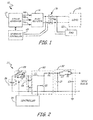
- FIG. 1 is a functional block diagram of a power generating system according to an embodiment of the present invention.
- FIG. 2 is a circuit diagram of a boost-mode portion of an electrical accumulator unit (EAU) according to an embodiment of the present invention.
- EAU electrical accumulator unit
- FIG. 3 is a circuit diagram of a boost-mode portion of an electrical accumulator unit (EAU) according to another embodiment of the present invention.
- EAU electrical accumulator unit
- FIG. 1 is a functional block diagram of power generating system 10 according to an embodiment of the present invention.
- Power generating system 10 includes three phase generator 12 connected via three phase outputs 14a, 14b, and 14c to supply power to AC/DC rectifier 16.
- Three phase generator 12 may also be referred to as generator 12.
- the AC/DC rectifier 16 converts the generate three phase power into DC power, and outputs the DC power to DC bus 18 (illustrated at DC link capacitor Cdc).
- Load 20 is connected to receive DC power from DC bus 18. Additionally connected to the DC power bus 18 is electrical accumulator unit (EAU) 22.
- EAU electrical accumulator unit
- Generator controller 24 is connected to three phase generator 12, and provides control signals for controlling the generator.
- Generator controller 24 is also connected to the output of the AC/DC rectifier 16 via power sensors, and is capable of detecting the power output of AC/DC rectifier 16 and the power demands of the load 20.
- Electrical accumulator unit 22 includes a power storage device (e.g., battery, super-capacitor, etc.) for storing energy. Electrical accumulator unit 22 provides for bi-directional power transfer between DC bus 18 and the power storage device. In instances in which excess power is available on DC bus 18, electrical accumulator unit 22 transfers power from DC bus 18 to the power storage device. This may be in response to three phase generator 12 generating excess power due to a demand to be charged by the energy storage device or in response to load 20 providing regenerative power back onto DC bus 18. Conversely, when power on DC bus 18 is insufficient, electrical accumulator unit 22 transfer power from the power storage device to DC bus 18 to augment the power provided by three-phase generator 12 and AC/DC rectifier 16.
- a power storage device e.g., battery, super-capacitor, etc.
- FIG. 2 is a circuit diagram of electrical accumulator unit 22 according to an embodiment of the present invention.
- Electrical accumulator unit 22 includes power storage device 26, bi-directional switch 28, power converter 30, filter circuit 32, controller 34 and dissipation circuit 36.
- electrical accumulator unit 22 includes a boost converter to increase or step-up the magnitude of the voltage supplied by power storage device 26 to DC bus 18.
- a simple boost converter comprising inductor L1, diode D1 and switch Q1 is employed.
- the boost converter may be implemented in parallel with other well-known DC-DC converter topologies, such as buck converters, buck-boost converters, etc., as well as combinations of several different types of converters.
- Controller 34 provides control signals to switch Q1, causing switch Q1 to selectively turn On and Off.
- Controller 34 controls the operation of switch Q l , as well as the operation of bi-directional switch 28, which includes switches Q2 and Q3, and diodes D2 and D3.
- controller 34 turns On switch Q3, and controls switch Q1 to be On and Off as required to provide the desired boost voltage onto DC bus 18.
- controller 34 turns switch Q1 On and Off using pulse width modulation (PWM techniques).
- PWM techniques pulse width modulation
- a buck converter (not shown) would be included to step down the voltage provided by DC bus 18, or a buck-boost converter may be employed to both step-up and step-down the voltage.
- Controller 34 would control the operation of the buck converter to transfer power from DC bus 18 to the energy storage device 26. Controller 34 would likewise close switch Q2 and open switch Q3 to allow power to be transferred from DC bus 18 to power storage device 26.
- Electrical accumulator unit 22 is turned Off following operation of the power converter 30 to transfer power from power storage device 26 to DC bus 18, or to transfer power from DC bus 18 to power storage device 26.
- power converter 30 is turned Off by turning Off switch Q1 and/or bi-directional switch 28.
- this method of turn-off results in residual energy stored in inductor L1 at the time of turn-off being discharged onto DC bus 18, potentially with undesirable effects.
- dissipation circuit 36 is connected to power converter 30. Assuming operation in the boost mode, in which power is being transferred from power storage device 26 to DC bus 18, when the operation is complete controller disconnects power storage device 26 from DC bus 18 by opening bi-directional switch 28 (e.g., turning Off switch Q3). Excess power stored in inductor L1 is dissipated by closing (or maintaining in a closed state) switch Q1 to create a recirculation circuit path that includes inductor L1, switch Q1, and dissipation circuit 36 (including resistor R1 and diode D4, which is forward biased or conducting in the recirculation circuit path). In this way, excess energy stored in inductor L1 is prevented from being discharged onto DC bus 18 when bi-directional switch 28 is turned Off.
- bi-directional switch 28 e.g., turning Off switch Q3
- Controller 34 may maintain switch Q1 in an On state for a defined period of time known to be of sufficient duration to dissipate excess energy, or may monitor the power dissipated by dissipation circuit 36 to determine when it is safe to switch Q1 Off.
- free-wheeling diode D4 may be sufficiently capable of dissipating energy stored in inductor L1. In this embodiment, energy-dissipating resistor R1 would not be required as part of dissipation circuit 36.
- FIG. 3 is a circuit diagram of an electrical accumulator unit according to another embodiment of the present invention.
- electrical accumulator unit 40 includes power source 26, bi-directional switch 28, input filter 32, and dissipation circuit 46.
- power converter 42 is implemented as a modular power converter that includes a plurality of individual power converters 42a, 42b connected in parallel with one another.
- Power converter 42a includes inductor L4, diode D5, and switch Q4, while power converter 42b includes inductor 1.5, diode D6, and switch Q5.
- Controller 44 generates control signals provided to bi-directional switch 28, as well as switches Q4 and Q5. Based on the control signals provided by controller 44, power converters 42a and 42b may be phase-shifted with respect to one another to reduce the ripples at the input and/or output of the electrical accumulator unit 22.
- bi-directional switch 28 and dissipation circuit 46 are connected in common with power converters 42a and 42b.
- Controller 44 turns Off electrical accumulator unit 44 by turning Off bi-directional switch 28 to disconnect power storage device 26 from power converter 42 and turning On each of the plurality of switches Q4, Q5 associated with power converters 42a, 42b respectively, to create a recirculation circuit path that includes dissipation circuit 46.
- Controller maintains switches Q5 and Q6 is an On state for at least an amount of time required to dissipate excess energy stored in inductors L4 and L5.
- dissipation circuit 46 is connected in common with each of the plurality of modular power converters 42a, 42b.
- each modular power converter 42a, 42b may include its own separate dissipation circuit.
Landscapes
- Engineering & Computer Science (AREA)
- Power Engineering (AREA)
- Dc-Dc Converters (AREA)
- Charge And Discharge Circuits For Batteries Or The Like (AREA)
Applications Claiming Priority (1)
| Application Number | Priority Date | Filing Date | Title |
|---|---|---|---|
| US13/048,286 US20120236439A1 (en) | 2011-03-15 | 2011-03-15 | Electrical accumulator units with safe turn-off |
Publications (2)
| Publication Number | Publication Date |
|---|---|
| EP2501013A2 true EP2501013A2 (fr) | 2012-09-19 |
| EP2501013A3 EP2501013A3 (fr) | 2015-08-12 |
Family
ID=45992039
Family Applications (1)
| Application Number | Title | Priority Date | Filing Date |
|---|---|---|---|
| EP12159290.1A Withdrawn EP2501013A3 (fr) | 2011-03-15 | 2012-03-13 | Unités d'accumulateur électrique à sécurité de coupure |
Country Status (2)
| Country | Link |
|---|---|
| US (1) | US20120236439A1 (fr) |
| EP (1) | EP2501013A3 (fr) |
Families Citing this family (4)
| Publication number | Priority date | Publication date | Assignee | Title |
|---|---|---|---|---|
| US8385032B1 (en) * | 2011-08-23 | 2013-02-26 | Futurewei Technologies, Inc. | High efficiency bridgeless PFC converter and method |
| DE112016006844T5 (de) * | 2016-05-12 | 2019-02-14 | Robert Bosch Gmbh | Batterietrennschaltungen und Verfahren zum Steuern einer Batterietrennschaltung |
| CN110249500B (zh) * | 2017-02-03 | 2022-07-22 | 东芝三菱电机产业系统株式会社 | 不间断电源装置 |
| US10193462B1 (en) * | 2017-10-11 | 2019-01-29 | Infineon Technologies Ag | Power converter using bi-directional active rectifying bridge |
Family Cites Families (5)
| Publication number | Priority date | Publication date | Assignee | Title |
|---|---|---|---|---|
| US3634728A (en) * | 1970-07-13 | 1972-01-11 | Jeumont Schneider | Current chopper for dc machines connected to the terminals of a source having an inductive impedance |
| FR2553945B1 (fr) * | 1983-10-21 | 1985-12-06 | Cem Comp Electro Mec | Dispositif vernier pour hacheur statique a semi-conducteurs |
| JP2004166441A (ja) * | 2002-11-15 | 2004-06-10 | Toyoda Mach Works Ltd | 電動パワーステアリング装置 |
| WO2008009025A2 (fr) * | 2006-07-14 | 2008-01-17 | The Board Of Trustees Of The University Of Illinois | Procédés et appareil pour fournir une réponse extrêmement rapide dans la commutation de convertisseurs de puissance |
| DE102008010980A1 (de) * | 2008-02-25 | 2009-08-27 | Robert Bosch Gmbh | Verfahren und Vorrichtung zum Entladen eines Hochspannungsnetzes |
-
2011
- 2011-03-15 US US13/048,286 patent/US20120236439A1/en not_active Abandoned
-
2012
- 2012-03-13 EP EP12159290.1A patent/EP2501013A3/fr not_active Withdrawn
Non-Patent Citations (1)
| Title |
|---|
| None |
Also Published As
| Publication number | Publication date |
|---|---|
| US20120236439A1 (en) | 2012-09-20 |
| EP2501013A3 (fr) | 2015-08-12 |
Similar Documents
| Publication | Publication Date | Title |
|---|---|---|
| EP2751919B1 (fr) | Convertisseur à double stimulation muni d'un chargeur intégré pour ups | |
| US7830686B2 (en) | Isolated high power bi-directional DC-DC converter | |
| US8723490B2 (en) | Controlling a bidirectional DC-to-DC converter | |
| US11362596B2 (en) | System and method for operating a system | |
| CN110603701A (zh) | 车辆用电源装置 | |
| WO2006115959A2 (fr) | Procede et appareil de fourniture d'alimentation sans coupure | |
| WO2017015670A1 (fr) | Commande d'hystérésis pour convertisseurs de puissance basés sur un transformateur | |
| KR101905343B1 (ko) | 저입력 및 저출력 리플을 갖는 벅 컨트롤러를 사용하는 플로팅 출력 전압 부스트 벅 조절기 | |
| JP2013521750A (ja) | 複数供給オンボード電源を備えた電力インバータ | |
| KR20120021219A (ko) | 양방향 dc?dc 컨버터용 소프트 스타트 방법 및 장치 | |
| EP2562021A2 (fr) | Dispositif et méthode de gestion d'énergie électrique régénérative | |
| WO2014032156A1 (fr) | Commande adaptative de commutation douce pour convertisseur de puissance | |
| JP6944058B2 (ja) | Dc/dcコンバータを備える車両充電器 | |
| EP2501013A2 (fr) | Unités d'accumulateur électrique à sécurité de coupure | |
| Srinivasan et al. | Decentralized control of a vehicular microgrid with constant power loads | |
| CN112366943A (zh) | 减少开关节点振铃的开关电路 | |
| KR20120010631A (ko) | 전력 변환 장치 | |
| JP2016518102A (ja) | バイパスコンデンサを備える昇圧型または降圧型コンバータ | |
| Yoo et al. | Transient current suppression scheme for bi-directional DC-DC converters in 42 V automotive power systems | |
| CN111315614B (zh) | 包括dc/dc转换器的车辆充电器 | |
| CN111669047A (zh) | 电源装置和电力系统 | |
| KR101695963B1 (ko) | 배터리 충방전 기능을 갖는 양방향 컨버터 회로 | |
| US11671048B2 (en) | Multiphase voltage transformer for a supply network and method for powering down an intermediate circuit voltage of this supply network | |
| US9276471B1 (en) | DC-to-DC converter controllers including clamping or boosting subsystems, and associated methods | |
| JP2005245160A (ja) | 電力変換装置 |
Legal Events
| Date | Code | Title | Description |
|---|---|---|---|
| PUAI | Public reference made under article 153(3) epc to a published international application that has entered the european phase |
Free format text: ORIGINAL CODE: 0009012 |
|
| AK | Designated contracting states |
Kind code of ref document: A2 Designated state(s): AL AT BE BG CH CY CZ DE DK EE ES FI FR GB GR HR HU IE IS IT LI LT LU LV MC MK MT NL NO PL PT RO RS SE SI SK SM TR |
|
| AX | Request for extension of the european patent |
Extension state: BA ME |
|
| PUAL | Search report despatched |
Free format text: ORIGINAL CODE: 0009013 |
|
| AK | Designated contracting states |
Kind code of ref document: A3 Designated state(s): AL AT BE BG CH CY CZ DE DK EE ES FI FR GB GR HR HU IE IS IT LI LT LU LV MC MK MT NL NO PL PT RO RS SE SI SK SM TR |
|
| AX | Request for extension of the european patent |
Extension state: BA ME |
|
| RIC1 | Information provided on ipc code assigned before grant |
Ipc: B60L 3/04 20060101ALI20150706BHEP Ipc: H02J 3/18 20060101AFI20150706BHEP Ipc: H02M 3/158 20060101ALI20150706BHEP |
|
| STAA | Information on the status of an ep patent application or granted ep patent |
Free format text: STATUS: THE APPLICATION IS DEEMED TO BE WITHDRAWN |
|
| 18D | Application deemed to be withdrawn |
Effective date: 20160213 |