EP2501016A2 - Integriertes Batterieladegerät - Google Patents
Integriertes Batterieladegerät Download PDFInfo
- Publication number
- EP2501016A2 EP2501016A2 EP11166088A EP11166088A EP2501016A2 EP 2501016 A2 EP2501016 A2 EP 2501016A2 EP 11166088 A EP11166088 A EP 11166088A EP 11166088 A EP11166088 A EP 11166088A EP 2501016 A2 EP2501016 A2 EP 2501016A2
- Authority
- EP
- European Patent Office
- Prior art keywords
- charging
- discharging
- circuit
- switch
- contact point
- Prior art date
- Legal status (The legal status is an assumption and is not a legal conclusion. Google has not performed a legal analysis and makes no representation as to the accuracy of the status listed.)
- Withdrawn
Links
Images









Classifications
-
- H—ELECTRICITY
- H02—GENERATION; CONVERSION OR DISTRIBUTION OF ELECTRIC POWER
- H02J—ELECTRIC POWER NETWORKS; CIRCUIT ARRANGEMENTS OR SYSTEMS FOR SUPPLYING OR DISTRIBUTING ELECTRIC POWER; SYSTEMS FOR STORING ELECTRIC ENERGY
- H02J7/00—Circuit arrangements for charging or discharging batteries or for supplying loads from batteries
- H02J7/50—Circuit arrangements for charging or discharging batteries or for supplying loads from batteries acting upon multiple batteries simultaneously or sequentially
- H02J7/575—Parallel/serial switching of connection of batteries to charge or load circuit
-
- H—ELECTRICITY
- H02—GENERATION; CONVERSION OR DISTRIBUTION OF ELECTRIC POWER
- H02J—ELECTRIC POWER NETWORKS; CIRCUIT ARRANGEMENTS OR SYSTEMS FOR SUPPLYING OR DISTRIBUTING ELECTRIC POWER; SYSTEMS FOR STORING ELECTRIC ENERGY
- H02J7/00—Circuit arrangements for charging or discharging batteries or for supplying loads from batteries
- H02J7/70—Circuit arrangements for charging or discharging batteries or for supplying loads from batteries characterised by the mechanical construction
- H02J7/751—Circuit arrangements for charging or discharging batteries or for supplying loads from batteries characterised by the mechanical construction concerning the insertion or the connection of the batteries
-
- H—ELECTRICITY
- H02—GENERATION; CONVERSION OR DISTRIBUTION OF ELECTRIC POWER
- H02J—ELECTRIC POWER NETWORKS; CIRCUIT ARRANGEMENTS OR SYSTEMS FOR SUPPLYING OR DISTRIBUTING ELECTRIC POWER; SYSTEMS FOR STORING ELECTRIC ENERGY
- H02J7/00—Circuit arrangements for charging or discharging batteries or for supplying loads from batteries
- H02J7/865—Battery or charger load switching, e.g. concurrent charging and load supply
-
- H—ELECTRICITY
- H02—GENERATION; CONVERSION OR DISTRIBUTION OF ELECTRIC POWER
- H02J—ELECTRIC POWER NETWORKS; CIRCUIT ARRANGEMENTS OR SYSTEMS FOR SUPPLYING OR DISTRIBUTING ELECTRIC POWER; SYSTEMS FOR STORING ELECTRIC ENERGY
- H02J2207/00—Details of circuit arrangements for charging or discharging batteries or supplying loads from batteries
- H02J2207/20—Charging or discharging characterised by the power electronics converter
Definitions
- the present invention relates to a battery charger, and more particularly to a charger designed for charging, discharging and supplying electric power to an AA or AAA rechargeable battery, and a manual switch synchronous control is provided to integrate a circuit structure with "an independent separate charging circuit and a combined serial discharging circuit.”
- a disposable battery namely a primary battery
- a rechargeable battery namely a secondary battery
- a rechargeable battery has a higher demands than that of a primary battery since a rechargeable battery can save costs and reduce contaminations of waste batteries.
- rechargeable batteries include lithium-ion (Li-ion) batteries, nickel metal hydride (Ni-MH) batteries, nickel cadmium (Ni-Cd) batteries and the rechargeable alkaline batteries, and these batteries are also known as secondary batteries.
- Li-ion lithium-ion
- Ni-MH nickel metal hydride
- Ni-Cd nickel cadmium
- a lithium battery with an organic electrolytic unit is used extensively in portable electronic devices due to its features of high-energy density, low temperature, and stable storage.
- the secondary battery such as the nickel metal hydride (Ni-MH), nickel cadmium (Ni-Cd) or alkaline rechargeable secondary battery has an energy storage density less than that of the lithium battery, yet its widely used AA or AAA battery sets an industrial specification, which is the main reason of its popularity up to now. However, its use still has the following insufficiencies:
- Another object of the present invention is to provide an integrated battery charger capable of charging one or more batteries separately to avoid the overheating, leak and undercharge that may occur when charging a plurality of serially-connected batteries.
- the batteries can be serially connected and directly combined in the same charger for outputting and discharging power.
- a stable standard USB power output of DC 5.0V can be supplied after the voltage is processed by a voltage regulator circuit.
- a further object of the present invention is to provide an integrated battery charger, serving as a charger when a battery is charged in an independent separate charging mode and removed from the charger for the use by an electronic product, or serving as a discharger when a manual switch is switched to a serially connected and combined discharging mode, and a stabilized DC power is outputted for charging a portable electronic product, or serving as an adaptor by directly supplying a DC charging power when there is no battery placed in the charger or the power of an electronic device is low.
- the battery charger becomes a portable power when it is carried out, such that when the power of an electronic device is low, the charger can serve as a backup secondary battery. Even one alkaline primary battery can be placed in the battery charger for the discharging, and thus the battery charger also serves as an emergency power supply device.
- the invention includes:
- the operation modes of the charger of the present invention include:
- the present invention is provided and integrated with the switching modes of the manual switch for constituting a circuit structure featuring an "independent separate charging and serially combined discharging mode” and a “synchronous switch control charging and discharging mode” without increasing the volume of the charger so as to overcome the problems of conventional chargers for nickel metal hydride batteries and nickel cadmium batteries and the problems of lithium batteries designed as a portable power, and to enhance the effect and safety of the charger.
- the charger 10 comprises: a casing 11, for containing and covering charging components (such as a switching power supply and a charging circuit), and a charging block 12 disposed on a surface of the casing 11 and having a plurality of charging compartments provided for placing a plurality of AA or AAA batteries B1 ⁇ B4 therein.
- charging compartments C1, C2, C3, C4 there are four charging compartments C1, C2, C3, C4, but the invention is not limited to such quantity only. In a small charger, there could be only two charging compartments.
- a charger with four charging compartments are used as an example for the description of a preferred embodiment and the illustration of its related drawings as follows.
- the casing 11 further comprises a plug 13 connectible to an external power source, wherein the plug 13 of this preferred embodiment is foldable and disposed at the bottom of the casing 11.
- a plug 13 connectible to an external power source
- an external power cable 131 or a replaceable plug 13 can be used instead for connecting with the external power source.
- the casing 11 includes at least one USB output port 60 formed on a side of the casing 11, and its connection socket is exposed from the casing 11 and used as an output terminal of an external DC power to be supplied.
- a manual switch 30 has an insulated operating interface 31 exposed from the casing 11, wherein the manual switch 30 of this preferred embodiment is, but not limited to, a two-stage slide switch. A press button or a differential switch is also applicable.
- the manual switch 30 has a plurality of pins 33, and each set of the mechanical switching unit SW 1 ⁇ SW n is formed by at least three contact points, and its structure will be described together with the charging circuit below.
- the charging block 12 as shown in FIG. 1 does not have an external cover on the top, it is not limited to this arrangement. That is, it may further have an external cover.
- the casing 10 includes a plurality of display units 29 which may be LEDs for displaying a charging status of each charging compartment C1 ⁇ C4. Each charging compartment has a positive terminal 121 and a corresponding negative terminal 122.
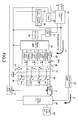
- FIG. 2 for a schematic circuit diagram of a preferred embodiment of the present invention, most of the components in this circuit structure are contained in the casing 11, and only a small number of components is exposed from the surface of the casing 11, and the circuit structure primarily comprises the following elements:
- An input power source 20 is provided for converting AC or DC power to DC power, charging the rechargeable batteries B1 ⁇ B4 on the charging block 12, and supplying a reference voltage source 21 to a charging control unit 22, wherein the charging control unit 22 is a microprocessor control unit (MCU), and controls the operation of each component of the charging circuit by executing a predetermined sequence of procedures.
- MCU microprocessor control unit
- the input terminal of the charging control unit 22 and the input power source 20 are coupled to a current control unit 23 and a voltage control unit 24, and a switch 28 is installed between therein.
- the charging circuit 14 composed of the foregoing components is a prior art, and thus will not be described here.
- the output terminal of the charging control unit 22 in accordance with the present invention further comprises a plurality of independent charging current control circuits 25 which can be circuit switches or components including but not limited to PWM driving circuits, and each of the output terminals is coupled to an anti-adverse-current element 251 which can be a diode D1 ⁇ D4 or MOSFET, such that the charging block 12 has four independent charging circuits 26.
- the first charging circuit to the fourth charging circuit 26 are formed respectively corresponding to the first charging compartment C1 to the fourth charging compartment C4.
- This circuit structure aims at providing an independent separate charging mode for the four pieces of batteries B1 ⁇ B4 placed in the four charging compartments C1 ⁇ C4 of the charging block 12. In other words, even if only one secondary battery is placed into the charging block 12, it still can be charged.
- a current detection component 27 is coupled to a negative terminal of the charging block 12, and the current detection component 27 can be a resistor R and is connected to the current and voltage control units 23, 24 for detecting current by the charging of the charging block 12 and using it as a voltage feedback current control to make adjustments.
- the charging current control circuit 25 is provided for setting a current, such that a constant charging current can be achieved.
- a manual switch 30 includes a switching insulated operating interface 31 disposed on a main body of the manual switch 30 and exposed from a surface of the casing 11 as shown in FIG. 1 .
- the manual switch 30 includes n-1 sets of mechanical switching units SW 1 ⁇ SW n-1 therein corresponding to a plurality of charging circuits n of the charging block 12, such that one set of mechanical switching unit is disposed between two adjacent charging circuits, and the last set of mechanical switching unit SW n of the manual switch 30 is an independent charging/discharging control module 40, and each of the mechanical switching units SW 1 ⁇ SW n has three contact points a, b, c, wherein each contact point a of the first to the (n-1) th sets of mechanical switching units SW 1 ⁇ SW n-1 is grounded or grounded through a current detection resistor R, and the contact point b is coupled to a positive terminal of a next charging circuit.
- SW 1 is coupled to the positive terminal of B2, and SW 3 is coupled to the positive terminal of B4, and the contact point c is electrically coupled to the negative terminal of each corresponding charging compartment C1 ⁇ C3, and the negative terminal 122 of the last set of charging compartment C4 is grounded, and the contact point a of the n th set of mechanical switching unit SW n serving as the charging/discharging control module 40 is a charging control terminal, and the contact point b is a discharging control terminal, and the contact point c is a power control terminal CONTROL H/L coupled to the input power source 20 or grounded to form a control circuit.
- n pieces of independent conductive terminals 32 installed at the bottom of the manual switch 30 is linked to shift synchronously when the insulated operating interface 31 of the manual switch 30 is switched.
- an end of the conductive terminal 32 is always electrically coupled to its corresponding contact point c and the other end of the conductive terminal 32 is electrically coupled to the contact point a or contact point b only.
- n is equal to 4, indicating that there are four charging circuits and four mechanical switching units, but the present invention is not limited to this number only.
- a charging control circuit A is comprised of a charging contact point a and a charging contact point c of the charging/discharging control module 40 and electrically coupled to the input power source 20 for controlling the ON/OFF of the input power source 20 or outputting a charging power to the charging block 12.
- a discharging control switch E comprises an input terminal d, an output terminal e and a control terminal f, wherein the input terminal d is coupled to a positive terminal 121 of the first charging compartment C1 in the charging block 12, and the output terminal e is coupled to a voltage regulator circuit 50, and the control terminal f is electrically coupled to the contact point b of the charging/discharging control module 40 for controlling the ON/OFF of the input terminal d and the output terminal e, such that the discharging current I d of each serially connected and combined battery B1 ⁇ Bn in the charging block 12 is outputted to the voltage regulator circuit 50.
- the discharging control switch E is a mechanical switch or an electronic switch linked to the contact point b of the charging/discharging control module 40, and the discharging control switch E is coupled to the voltage regulator circuit 50 externally or built in the voltage regulator circuit 50.
- the voltage regulator circuit 50 is used for boosting or stepping down an input power to a predetermined DC voltage.
- At least one USB output port 60 is coupled to an output terminal of the voltage regulator circuit 50, and a socket of the USB output port 60 is exposed from the casing 11.
- the contact point b is coupled to the discharging control switch E, and each contact point b of the remaining mechanical switching units SW 1 ⁇ SW 3 , is electrically coupled to a positive terminal of the next charging compartment C2-C4 respectively, such that when the manual switch 30 as shown in FIGS. 3A and 6A is switched down by the insulated operating interface 31, the conductive terminal 32 at the contact point c is driven to shift downward synchronously.
- the negative terminals of the first to fourth charging compartments C1 ⁇ C4 of the charging circuit are grounded, so that each charging compartment C1 ⁇ C4 becomes an independent charging circuit.
- the charger 10 of the present invention can charge even one battery only at a time, not only providing a convenient use, but also avoiding the overheating and undercharge.
- the batteries B1 ⁇ B4 can be charged, and the fully charged one can be removed from the charger 10 first for its use.
- the manual switch 30 is switched upward as shown in FIGS. 3B and 6B , and the exposed insulated operating interface 31 in FIG. 1 is pushed to another side.
- the conductive terminal 32 at the contact point c is shifted upward synchronously, and turning each contact point b of the mechanical switching units SW 1 ⁇ SW 4 ON.
- each battery B1 ⁇ B4 in the charging block 12 becomes a serially connected and combined discharging circuit, and the discharging control switch E is ON to output the discharging current I d .
- the input terminal of the voltage regulator circuit 50 is coupled to the output terminal 42 of the discharging control switch E for regulating the voltage of the discharging current I d .
- the voltage regulator circuit 50 is a synchronous buck/boost DC/DC converter, and the buck/boost IC technology of this sort has been used extensively, and can provide a stable and accurate voltage output, and its internal circuit is a prior art and thus will not be described in detail here.
- the present invention adopts the foregoing voltage regulator circuit 50 that can regulate the discharge of different batteries by stepping the voltage up or down so as to assure that the electric power supply from the USB output port 60 has a stable and accurate voltage.
- the n th set of mechanical switching unit SW n of the manual switch 30 is used as the charging/discharging control module 40, and its contact point a is provided for turning on the charging control circuit A, and the contact point b is provided for turning on the discharging control switch E, which form a control with two opposite functions.
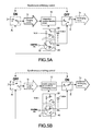
- each mechanical switching unit SW 1 ⁇ SW n when the manual switch 30 is switched to the charging mode, the contact point c and the contact point a of each mechanical switching unit SW 1 ⁇ SW n are ON, such that each battery in the charging block 12 is an independent separate charging circuit, and the charging control circuit A is ON to allow the charging current I c to enter the charging block 12; meanwhile the discharging control switch E is turned OFF automatically to situate at a charging status as shown in FIG. 5A .
- each mechanical switching unit SW 1 ⁇ SW n is ON, and each battery in the charging block 12 is a serially connected and combined discharging circuit, and the charging control circuit A is turned OFF, and the discharging control switch E is turned ON to output the discharging current I d .
- a charging/discharging circuit and a switch is provided for a synchronous switching control, such that when the charging block 12 charges the battery, the output of discharging current I d is turned off automatically, so as to prevent the interference to the output circuit from affecting the charging process.
- the charging control circuit A and the discharging control switch E are coupled to the contact point a and the contact point b of the charging/discharging control module 40 respectively for the control, wherein the contact points a, c of the charging/discharging control module 40 are the contact points a, c of the charging control circuit A in this preferred embodiment, and the contact point b is electrically coupled to the discharging control switch E.
- the contact points a, c are ON
- the charging control circuit A will be ON. If the contact points b, c are ON, a signal will be transmitted to make the discharging control switch E ON.
- the charging control circuit A and the discharging control switch 40B are not limited to those illustrated in the figures only, but any method capable of switching the contact points a, b of the charging/discharging control module 40 ON/OFF synchronously can be adopted. Since the contact points a, b will not be turned ON at the same time, they are in opposite switching control state. Therefore, one of the contact points is ON, while the other one is OFF.
- the present invention applies this technical measure to achieve the switching purpose conveniently, so that the present invention can integrate several functions into one charger without increasing the overall volume or the complicity of the structure.
- the present invention further adopts a manual switch 30 to overcome the shortcomings of the conventional electronic switch such as the internal impedance causing power loss, step-down voltage causing power drop, and delay affecting the charging efficiency of the charger.
- the present invention skillfully uses the manual switch 30 to achieve the aforementioned features of "independent separate charging and serially connected and combined discharging” and "a one-time control for switching to a charging mode and a discharging mode synchronously".
- the slide switch is a prior art, and thus its switching principle will not be described in details here.
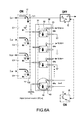
- the present invention further includes a two-stage slide switch with a plurality of pins as shown in FIGS. 6A and 6B .
- the manual switch 30 includes 12 contact points therein and 12 pins 33 extended from the manual switch 30.
- Every three points a, b, c as a group is set to constitute four sets mechanical switching units SW 1 ⁇ SW 4 , wherein the four conductive terminals 32 are shifted together with the insulated operating interface 31 to synchronously turn all the contact points c and all contact points a ON or synchronously turn the contact points c and the contact points b ON. Since the switching is synchronous, there will be no delay, internal impedance or voltage drop, and the present invention can overcome the long-standing problems and shortcomings of the conventional electronic switch to enhance the charging and discharging performance.
- the number of sets can be changed to fit the charging circuit 26.
- n charging circuits 26 will have n sets of mechanical switching units, and the n th mechanical switching unit SW n is the charging/discharging control module 40.
- the present invention may have more than four sets (such as eight sets) of charging circuits.
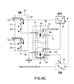
- the present invention may have two sets of charging circuits as shown in FIGS. 4A , 4B , 6C and 6D .
- the rechargeable battery B1 ⁇ B4 can be placed in each corresponding charging compartment C1 ⁇ C4. If there are four independent charging circuits in the charging block 12 as shown in FIGS. 6A and 6B , there will be four independent charging currents I c1 ⁇ I c4 . However, the present invention may electrically connect two charging compartments C1, C2 and C3, C4 as shown in FIGS. 6C and 6D , such that the charging circuit provides two independent charging currents I c1 ⁇ I c2 , which is also applicable to the present invention.
- a preferred embodiment of the present invention may have n sets of charging circuits in the charging block, wherein n is equal to 2, 4 or 8, and n-1 sets of mechanical switching units SW 1 ⁇ SW n-1 corresponding to the manual switch 30 include 1 set, 3 sets or 7 sets, and the last n th set of independent mechanical switching unit SW n may be added to the 1 set, 3 sets or 7 sets to serve as the charging/discharging control module 40.
- the switching power supply 20 is connected to an auxiliary power supply 70 and then to a voltage regulator circuit 50 for regulating the voltage and a standard USB power is provided from a USB output port 60.
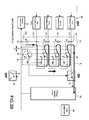
- Step S1 determines whether or not there is an input power source 20, and if there is an input power source 20, then Step S2 determines whether or not the manual switch 30 is switched to a charging mode or a discharging mode. If Step 2 determines that the manual switch is in a charging mode, then Step S3 sets the battery in the charging block 12 to an independent separate charging circuit mode. Now, the charging/discharging control module 40 synchronously turn the discharging control switch E OFF and the charging control circuit A ON to set a charging mode, and then Step S4 determines whether or not there is a rechargeable battery in the charging block 12.
- Step 5 turns on an independent separate charging circuit if Step 4 determines that there is a rechargeable battery, and step S6 determines whether or not the charging is completed, and will continue charging when not completed, or else enter into Step S7 to stop charging the battery if it is completed.
- Step S6 determines whether or not the charging is completed, and will continue charging when not completed, or else enter into Step S7 to stop charging the battery if it is completed.
- a slight charging still can be performed after the charging process ends, and the details will not be described here.
- Step S2 if it is determined that the manual switch 30 is switched to the discharging mode, Step 8 will take place.
- the circuit in the charging block 12 is a serially connected and combined discharging circuit, and the charging/discharging control module 40 synchronously turns the charging control circuit A OFF, the input power source 20 OFF, and the discharging control switch E ON to set it at a discharging mode.
- Step S9 determines whether or not there is a battery, and Step 10 takes place to start the serially connected and combined discharging circuit if there is a battery in the charging block 12, such that each battery is serially connected and discharged.
- Step S11 For a secondary battery with a lower voltage (4.8V), Step S11 will regulate the voltage by stepping up the voltage automatically by a voltage regulator circuit 50. For a primary battery with a higher voltage (6V), Step S11 will step down the voltage. The step-up and step-down of the voltage in Step S11 is performed by the voltage regulator circuit 50, and a stable electric power with a standard USB voltage of DC 5.0V is output to Step 12 for an external electronic product.
- Step S1 if it is determined that there is no input power source 20, the procedure will enter S14 to determine whether or not the manual switch 30 is switched to a discharging mode or a charging mode, and if it is determined that the manual switch 30 is switched to the charging mode, then the procedure ends. If it is determined that the manual switch 30 is switched to the discharging mode, then Step S 15 takes place. Now, the circuit in the charging block 12 is a serially connected discharging circuit, and an emergency backup battery can be placed into the charging block 12.
- Step S16 determines whether or not there is a battery in the charging block 12, and step S 17 takes place if there is a battery in the charging block 12, and then the Steps S17 ⁇ S18 are the same as the Steps S10 ⁇ S11, and finally in Step S12, an electric power of standard voltage is output from the USB output port 60.
- Step S1 if it is determined that there is an input power source 20, another procedure takes place at the same time of S2, wherein the input power source 20 is inputted directly to the auxiliary power supply 70 of Step S 13, and the auxiliary power supply 70 stabilize the voltage in Step S11 and enters Step S12 to output an electric power of a standard voltage from the USB output port 60.
- the auxiliary power supply 70 supplies electric power, the discharging mode of Step S8 is disabled.
- the charger 10 of the present invention can be used with the following modes:
- the present invention uses a manual switch to integrate the features of an "independent separate charging circuit” and a “serially connected and combined discharging circuit” to synchronously control the switch and ON/OFF of the charging and discharging circuits of the charging compartment.
- the invention not only provides a convenient operation, but also overcomes the shortcomings of the conventional chargers and achieves the effects of enhancing the charging and discharging performance, and integrates several functions into one charger to improve its practicability.
Landscapes
- Engineering & Computer Science (AREA)
- Power Engineering (AREA)
- Charge And Discharge Circuits For Batteries Or The Like (AREA)
- Secondary Cells (AREA)
Applications Claiming Priority (1)
| Application Number | Priority Date | Filing Date | Title |
|---|---|---|---|
| TW100109262A TW201240270A (en) | 2011-03-18 | 2011-03-18 | Integrated battery charger |
Publications (2)
| Publication Number | Publication Date |
|---|---|
| EP2501016A2 true EP2501016A2 (de) | 2012-09-19 |
| EP2501016A3 EP2501016A3 (de) | 2014-04-09 |
Family
ID=45715271
Family Applications (1)
| Application Number | Title | Priority Date | Filing Date |
|---|---|---|---|
| EP11166088.2A Withdrawn EP2501016A3 (de) | 2011-03-18 | 2011-05-13 | Integriertes Batterieladegerät |
Country Status (5)
| Country | Link |
|---|---|
| US (1) | US8643325B2 (de) |
| EP (1) | EP2501016A3 (de) |
| JP (1) | JP2012200126A (de) |
| CN (1) | CN102684243A (de) |
| TW (1) | TW201240270A (de) |
Cited By (4)
| Publication number | Priority date | Publication date | Assignee | Title |
|---|---|---|---|---|
| CN103236720A (zh) * | 2012-11-15 | 2013-08-07 | 朱治民 | 积木式移动电源与充电器的组合装置 |
| CN106532810A (zh) * | 2016-10-28 | 2017-03-22 | 深圳市劲松安防科技有限公司 | 一种不间断电源控制电路及含该电路的摄像机 |
| CN109713764A (zh) * | 2019-03-06 | 2019-05-03 | 常州格力博有限公司 | 电池包 |
| CN114028821A (zh) * | 2021-12-06 | 2022-02-11 | 广东乐心医疗电子股份有限公司 | 机械盒 |
Families Citing this family (44)
| Publication number | Priority date | Publication date | Assignee | Title |
|---|---|---|---|---|
| CN102185368A (zh) * | 2011-05-12 | 2011-09-14 | 鸿富锦精密工业(深圳)有限公司 | 充电器 |
| KR101294025B1 (ko) * | 2011-08-02 | 2013-08-08 | 숭실대학교산학협력단 | 휴대 기기, 배터리 팩, 배터리부 제어 장치 및 방법 |
| TW201249057A (en) * | 2011-12-02 | 2012-12-01 | Samya Technology Co Ltd | An MCU integration battery charger/discharger |
| CN104079015B (zh) * | 2013-03-27 | 2018-06-01 | 联想(北京)有限公司 | 充电设备、充电方法和电子设备 |
| JP5899173B2 (ja) * | 2013-09-11 | 2016-04-06 | 日立建機株式会社 | 給電装置 |
| USD718710S1 (en) | 2013-09-12 | 2014-12-02 | The Gillette Company | Battery charger |
| CN103594750B (zh) * | 2013-11-22 | 2016-03-02 | 上海航天电源技术有限责任公司 | 一种耐浮充锂离子电池模块及其浮充方法 |
| JP2015128336A (ja) * | 2013-12-27 | 2015-07-09 | 株式会社東芝 | 電源回路及び電子機器 |
| JP6193150B2 (ja) * | 2014-02-26 | 2017-09-06 | 株式会社マキタ | 充電器 |
| JP2015192565A (ja) * | 2014-03-28 | 2015-11-02 | 日立工機株式会社 | 充電装置及び電源装置 |
| KR101554104B1 (ko) * | 2014-06-17 | 2015-09-17 | 주식회사 쓰리에스솔루션 | 다목적 전원충전장치 |
| US9385542B2 (en) | 2014-06-26 | 2016-07-05 | Hong Kong Applied Science and Technology Research Institute Company, Limited | Serial multi-battery charger with independent simultaneous charge and discharge |
| CN104111910A (zh) * | 2014-07-18 | 2014-10-22 | 山东超越数控电子有限公司 | 一种usb接口过载自动切换方法 |
| EP3198700A1 (de) * | 2014-09-26 | 2017-08-02 | Brightcharger Europe Oy Ltd. | Unterbrechen der elektrischen ladestromversorgung |
| KR20160112143A (ko) | 2015-03-18 | 2016-09-28 | 삼성전자주식회사 | 전자 장치 및 전자 장치에서의 디스플레이 패널의 화면 업데이트 방법 |
| CN104901354A (zh) * | 2015-03-23 | 2015-09-09 | 托马斯·达密兹 | 一种电池系统和包括该电池系统的电源设备 |
| WO2016209698A1 (en) | 2015-06-26 | 2016-12-29 | Amber Kinetics, Inc. | Switching fabric for energy storage and power conversion |
| US20170063127A1 (en) * | 2015-08-26 | 2017-03-02 | The Aes Corporation | Battery Backup Capacity Method and System |
| JP6931347B2 (ja) * | 2015-09-08 | 2021-09-08 | ボルト テクノロジー リミテッド | 電圧調整装置を備えた電池 |
| CN105811510B (zh) * | 2016-04-27 | 2018-05-22 | 深圳市文德丰科技有限公司 | 一种应用于移动通讯设备的多功能充电宝 |
| CN106130372B (zh) * | 2016-07-21 | 2018-07-03 | 唐山东唐电气股份有限公司 | 交流电无变升压电源 |
| TWI633738B (zh) * | 2016-09-07 | 2018-08-21 | 華碩電腦股份有限公司 | 儲能單元充放電模組及其充放電方法 |
| US10177576B2 (en) * | 2016-09-20 | 2019-01-08 | Richtek Technology Corporation | Charger circuit and capacitive power conversion circuit and reverse blocking switch circuit thereof |
| USD816023S1 (en) * | 2016-10-12 | 2018-04-24 | Duracell U.S. Operations, Inc. | Battery charger |
| CN107979121B (zh) * | 2016-10-21 | 2020-02-07 | 立锜科技股份有限公司 | 充电电路及其电源转换电路 |
| US10177420B2 (en) * | 2016-10-21 | 2019-01-08 | Richtek Technology Corporation | Charger circuit and power conversion circuit thereof |
| JP6389224B2 (ja) * | 2016-11-17 | 2018-09-12 | 株式会社マキタ | 電動工具用充電装置 |
| USD822597S1 (en) * | 2017-04-21 | 2018-07-10 | Energizer Brands, Llc | Charger |
| CN109152125A (zh) * | 2017-06-28 | 2019-01-04 | 群光电能科技股份有限公司 | 发光装置及其驱动方法 |
| EP3422433A1 (de) * | 2017-06-29 | 2019-01-02 | Vestel Elektronik Sanayi ve Ticaret A.S. | Batterieanordnung und elektronische vorrichtung |
| CN107196378A (zh) * | 2017-07-14 | 2017-09-22 | 深圳天珑无线科技有限公司 | 充放电电路与充放电底座 |
| US12665435B2 (en) * | 2017-09-22 | 2026-06-23 | Urban Electric Power Inc. | System to charge cells assembled into a battery |
| JP6427819B1 (ja) * | 2018-06-04 | 2018-11-28 | 株式会社日本ビデオシステム | バッテリー充電器、バッテリーシステム |
| KR102405321B1 (ko) | 2018-12-21 | 2022-06-02 | 광동 오포 모바일 텔레커뮤니케이션즈 코포레이션 리미티드 | 복수의 셀을 충전하는 방법, 장치 및 전자 기기 |
| US20200266643A1 (en) * | 2019-02-15 | 2020-08-20 | Qualcomm Incorporated | Methods and apparatuses for dual port battery charging |
| JP7248471B2 (ja) * | 2019-03-25 | 2023-03-29 | ソニー・オリンパスメディカルソリューションズ株式会社 | 充電装置および内視鏡システム |
| CN112117817B (zh) * | 2019-06-19 | 2022-08-09 | Oppo广东移动通信有限公司 | 驱动电路、电子设备以及控制充电方法 |
| KR102519757B1 (ko) * | 2020-05-22 | 2023-04-07 | 민일홍 | 배터리 충전 시스템 |
| CN111682615A (zh) * | 2020-06-18 | 2020-09-18 | 格力博(江苏)股份有限公司 | 充电控制电路、充电装置及充电系统 |
| CN112744101B (zh) * | 2020-12-25 | 2023-02-17 | 中国第一汽车股份有限公司 | 充放电控制系统、方法及交通工具 |
| JP7884227B2 (ja) * | 2021-01-27 | 2026-07-03 | パナソニックIpマネジメント株式会社 | 蓄電デバイス制御システム及びバックアップ電源システム |
| CN113472045B (zh) * | 2021-07-08 | 2023-11-21 | 苏州赛芯电子科技股份有限公司 | 锂电池充放电保护电路和锂电池保护系统 |
| USD1110948S1 (en) * | 2024-10-10 | 2026-02-03 | Xuejiao Tan | Battery charger |
| USD1104959S1 (en) * | 2024-10-11 | 2025-12-09 | Kodai Industries Ltd | Battery charger |
Family Cites Families (13)
| Publication number | Priority date | Publication date | Assignee | Title |
|---|---|---|---|---|
| GB1448053A (en) * | 1974-03-08 | 1976-09-02 | Kinder B | Electrical charging systems |
| CA2149016C (en) * | 1993-09-15 | 2005-07-12 | Ericsson Inc. | Power systems for plug-in modules |
| US5811959A (en) * | 1996-12-27 | 1998-09-22 | Kejha; Joseph B. | Smart circuit board for multicell battery protection |
| EP1363379A3 (de) * | 2002-05-13 | 2004-01-02 | Luxon Energy Devices Corporation | Leistungsmodul zur Erzeugung von Energieimpulsen unterschiedlicher Stärke |
| US7391184B2 (en) * | 2005-02-16 | 2008-06-24 | Dell Products L.P. | Systems and methods for integration of charger regulation within a battery system |
| US20060232243A1 (en) * | 2005-04-13 | 2006-10-19 | Dabdoub David A | Electrical appliance for use with batteries |
| TWM297579U (en) * | 2006-01-30 | 2006-09-11 | Samya Technology Co Ltd | Portable mobile power supply |
| TWM303494U (en) * | 2006-06-16 | 2006-12-21 | Shin-Bei Shie | Portable power source device |
| US7705560B2 (en) * | 2006-08-15 | 2010-04-27 | N. P. Johnson Family Limited Partnership | Voltage controller |
| CN201213190Y (zh) * | 2008-05-19 | 2009-03-25 | 廖生兴 | 可调整使用角度的插头结构 |
| CN201478851U (zh) * | 2009-08-03 | 2010-05-19 | 浙江联龙电子电器有限公司 | 一种镍铬镍氢aaa、aa电池充电器 |
| TW201242212A (en) * | 2011-04-01 | 2012-10-16 | Samya Technology Co Ltd | Improved independent serial battery detecting charger |
| US9130384B2 (en) * | 2011-10-06 | 2015-09-08 | Prong, Inc. | Smart phone and/or consumer electronics device charger system |
-
2011
- 2011-03-18 TW TW100109262A patent/TW201240270A/zh not_active IP Right Cessation
- 2011-04-01 CN CN2011100813997A patent/CN102684243A/zh active Pending
- 2011-04-15 JP JP2011091054A patent/JP2012200126A/ja active Pending
- 2011-04-26 US US13/094,161 patent/US8643325B2/en not_active Expired - Fee Related
- 2011-05-13 EP EP11166088.2A patent/EP2501016A3/de not_active Withdrawn
Non-Patent Citations (1)
| Title |
|---|
| None |
Cited By (6)
| Publication number | Priority date | Publication date | Assignee | Title |
|---|---|---|---|---|
| CN103236720A (zh) * | 2012-11-15 | 2013-08-07 | 朱治民 | 积木式移动电源与充电器的组合装置 |
| CN103236720B (zh) * | 2012-11-15 | 2016-03-23 | 朱治民 | 积木式移动电源与充电器的组合装置 |
| CN106532810A (zh) * | 2016-10-28 | 2017-03-22 | 深圳市劲松安防科技有限公司 | 一种不间断电源控制电路及含该电路的摄像机 |
| CN109713764A (zh) * | 2019-03-06 | 2019-05-03 | 常州格力博有限公司 | 电池包 |
| CN109713764B (zh) * | 2019-03-06 | 2024-03-12 | 格力博(江苏)股份有限公司 | 电池包 |
| CN114028821A (zh) * | 2021-12-06 | 2022-02-11 | 广东乐心医疗电子股份有限公司 | 机械盒 |
Also Published As
| Publication number | Publication date |
|---|---|
| US8643325B2 (en) | 2014-02-04 |
| TW201240270A (en) | 2012-10-01 |
| JP2012200126A (ja) | 2012-10-18 |
| CN102684243A (zh) | 2012-09-19 |
| TWI487243B (de) | 2015-06-01 |
| US20120235641A1 (en) | 2012-09-20 |
| EP2501016A3 (de) | 2014-04-09 |
Similar Documents
| Publication | Publication Date | Title |
|---|---|---|
| US8643325B2 (en) | Integrated battery charger | |
| US8860371B2 (en) | Series battery charger with the function of separate detection | |
| US12421928B2 (en) | Multifunctional battery booster | |
| US20130169228A1 (en) | Mcu integration battery charger/discharger | |
| EP2195902B1 (de) | Schaltkreisanordnung mit mehreren batterien | |
| JP3183420U (ja) | 携帯式ワイヤレス充電器 | |
| US6404168B1 (en) | Auxiliary battery for portable devices | |
| US20110012552A1 (en) | Electrical power source | |
| US20130049675A1 (en) | Output connector equipped battery pack, battery-pack-and-battery-driven-device system, and charging method by using battery pack | |
| KR101562015B1 (ko) | 병렬 연결된 이차 전지들의 충전 제어 장치 및 방법 | |
| US9190908B2 (en) | Protection cover allowing handheld device to reversely discharge | |
| CN101188320A (zh) | 用于便携式电子设备电池和便携式电话电池的充电设备 | |
| US20090265570A1 (en) | Battery structure of portable electronic device | |
| JP2008048473A (ja) | 充電器 | |
| WO2021185307A1 (zh) | 直流电源 | |
| JP2006211778A (ja) | 多機能ニッケル水素またはニッケルカドミウム電池充電器及び緊急給電器 | |
| US20040012368A1 (en) | Method and apparatus for charging a rechargeable cell | |
| CN201868533U (zh) | 一种可充放电控制电池、嵌套电池及一种电动剃须刀 | |
| KR101613058B1 (ko) | 충방전기능을 갖는 휴대단말용 배터리팩 파우치 장치 | |
| CN102005793A (zh) | 一种可充放电控制电池、嵌套电池及一种电动剃须刀 | |
| EP2047353A2 (de) | Stromrichter mit integrierter batterie | |
| JPH10275635A (ja) | 電池を内蔵する充電器 | |
| CN217335109U (zh) | 电源转换装置 | |
| CN2935483Y (zh) | 便携式数码设备的外置电池包 | |
| US20080012427A1 (en) | Power converter with integral battery |
Legal Events
| Date | Code | Title | Description |
|---|---|---|---|
| PUAI | Public reference made under article 153(3) epc to a published international application that has entered the european phase |
Free format text: ORIGINAL CODE: 0009012 |
|
| AK | Designated contracting states |
Kind code of ref document: A2 Designated state(s): AL AT BE BG CH CY CZ DE DK EE ES FI FR GB GR HR HU IE IS IT LI LT LU LV MC MK MT NL NO PL PT RO RS SE SI SK SM TR |
|
| AX | Request for extension of the european patent |
Extension state: BA ME |
|
| PUAL | Search report despatched |
Free format text: ORIGINAL CODE: 0009013 |
|
| AK | Designated contracting states |
Kind code of ref document: A3 Designated state(s): AL AT BE BG CH CY CZ DE DK EE ES FI FR GB GR HR HU IE IS IT LI LT LU LV MC MK MT NL NO PL PT RO RS SE SI SK SM TR |
|
| AX | Request for extension of the european patent |
Extension state: BA ME |
|
| RIC1 | Information provided on ipc code assigned before grant |
Ipc: H02J 7/00 20060101AFI20140228BHEP |
|
| STAA | Information on the status of an ep patent application or granted ep patent |
Free format text: STATUS: THE APPLICATION IS DEEMED TO BE WITHDRAWN |
|
| 18D | Application deemed to be withdrawn |
Effective date: 20141010 |