EP2501031A1 - Elektrogerät mit energieerzeugungsfunktion - Google Patents
Elektrogerät mit energieerzeugungsfunktion Download PDFInfo
- Publication number
- EP2501031A1 EP2501031A1 EP09851237A EP09851237A EP2501031A1 EP 2501031 A1 EP2501031 A1 EP 2501031A1 EP 09851237 A EP09851237 A EP 09851237A EP 09851237 A EP09851237 A EP 09851237A EP 2501031 A1 EP2501031 A1 EP 2501031A1
- Authority
- EP
- European Patent Office
- Prior art keywords
- operation panel
- force
- rotating shaft
- electric apparatus
- main body
- Prior art date
- Legal status (The legal status is an assumption and is not a legal conclusion. Google has not performed a legal analysis and makes no representation as to the accuracy of the status listed.)
- Granted
Links
Images





Classifications
-
- H—ELECTRICITY
- H02—GENERATION; CONVERSION OR DISTRIBUTION OF ELECTRIC POWER
- H02N—ELECTRIC MACHINES NOT OTHERWISE PROVIDED FOR
- H02N2/00—Electric machines in general using piezoelectric effect, electrostriction or magnetostriction
- H02N2/18—Electric machines in general using piezoelectric effect, electrostriction or magnetostriction producing electrical output from mechanical input, e.g. generators
-
- H—ELECTRICITY
- H10—SEMICONDUCTOR DEVICES; ELECTRIC SOLID-STATE DEVICES NOT OTHERWISE PROVIDED FOR
- H10N—ELECTRIC SOLID-STATE DEVICES NOT OTHERWISE PROVIDED FOR
- H10N30/00—Piezoelectric or electrostrictive devices
- H10N30/30—Piezoelectric or electrostrictive devices with mechanical input and electrical output, e.g. functioning as generators or sensors
- H10N30/308—Membrane type
-
- G—PHYSICS
- G08—SIGNALLING
- G08C—TRANSMISSION SYSTEMS FOR MEASURED VALUES, CONTROL OR SIMILAR SIGNALS
- G08C2201/00—Transmission systems of control signals via wireless link
- G08C2201/10—Power supply of remote control devices
- G08C2201/11—Energy harvesting
- G08C2201/112—Mechanical energy, e.g. vibration, piezoelectric
Definitions
- the present invention relates to an electric apparatus provided with power generating function that generates an electromotive force when deformed.
- Conventionally known power generation structures using a piezoelectric device includes, for example, a structure in which an electromotive force is generated by directly applying an external force to a piezoelectric device to deform it (e.g., see Patent Document 1) and a structure in which an electromotive force is generated by indirectly applying a force, such as wind or the like, to a piezoelectric device to deform it (e.g., see Patent Document 2).
- a mobile phone including a secondary battery that can be recharged by the output of the piezoelectric device has been proposed (e.g., see Patent Document 3).
- This mobile phone obtains an electromotive force from the piezoelectric device deformed by a force applied when a user pushes an input key.
- the power generation structure as described in Patent Documents 1 and 2 is a structure in which power is generated by only one piezoelectric device. Since the amount of power generated by one piezoelectric device is small, it is not realistic that the electric apparatus is driven by this power.
- the piezoelectric device is deformed by the force applied when the user pushes the input key.
- the force for pushing the input key may not be able to sufficiently deform the piezoelectric device.
- the insufficient deformation amount results in power generation insufficient to drive the electric apparatus.
- an object of the present invention to provide an electric apparatus provided with power generating function that can be sufficiently driven by an electromotive force obtained from a power generation device, such as a piezoelectric device.
- the invention according to claim 1 provides an electric apparatus provided with power generating function, which includes: a main body; an operation panel provided on one side surface of the main body; an operation means provided on the operation panel, to be exposed to the outside of the electric apparatus; and a power generator having a power generation device that generates an electromotive force when deformed, wherein the operation panel can be rotated with respect to the main body by an operation force applied to the operation means, and wherein the power generation device of the power generator generates an electromotive force when deformed by a force from the operation panel rotated by the operation force.
- the invention according to claim 2 provides the electric apparatus, wherein the operation panel can be rotated with respect to the main body about a rotating shaft provided along at least one side of the sides of the operation panel.
- the invention according to claim 3 provides the electric apparatus, wherein, when the operation force is not applied to the operation means, the operation panel is placed at an angle with respect to another side surface of the main body opposite to the operation panel at which the operation panel is not in approximately parallel with the another side surface, and wherein, when the operation force is applied to the operation means, the operation panel is placed at an angle with respect to the another side surface of the main body opposite to the operation panel at which the operation panel is in approximately parallel with the another side surface.
- the invention according to claim 4 provides the electric apparatus, wherein the operation panel includes a first operation panel and a second operation panel, wherein the first operation panel can be rotated with respect to the main body about a first rotating shaft provided along at least one side of the sides of the first operation panel, wherein the second operation panel can be rotated with respect to the main body about a second rotating shaft provided along at least one side of the sides of the second operation panel, and wherein the side along which the second rotating shaft of the second operation panel is provided is a side of the sides of the second operation panel that is in approximately parallel with the first rotating shaft and is the farthest from the first rotating shaft.
- the invention according to claim 5 provides the electric apparatus, wherein, when the operation force is not applied to the operation means, the first operation panel is placed at an angle with respect to another side surface of the main body opposite to the first operation panel at which the first operation panel is not in approximately parallel with the another side surface, wherein, when the operation force is applied to the operation means, the first operation panel is placed at an angle with respect to the another side surface of the main body opposite to the first operation panel at which the first operation panel is in approximately parallel with the another side surface, wherein, when the operation force is not applied to the operation means, the second operation panel is placed at an angle with respect to another side surface of the main body opposite to the second operation panel at which the second operation panel is not in approximately parallel with the another side surface and also is not in approximately parallel with the first operation panel when the operation force is not applied to the operation means, and wherein, when the operation force is applied to the operation means, the second operation panel is placed at an angle with respect to the another side surface of the main body opposite to the second
- the invention according to claim 6 provides the electric apparatus, wherein a first extension plate is provided on the first operation panel at a position far from the first rotating shaft of the first operation panel, wherein a second extension plate is provided on the second operation panel at a position far from the second rotating shaft of the second operation panel, and wherein the first extension plate and the second extension plate have a shape such that the first extension plate and the second extension plate do not interfere with each other.
- the invention according to claim 7 provides the electric apparatus, wherein a plurality of power generation device modules each formed by layering a plurality of the power generation devices are installed adjacent to each other in a direction perpendicular to the rotating shaft of the operation panel, and wherein the plurality of power generation device modules each include the power generation devices the number of layers of which increases gradually from a position near the rotating shaft of the operation panel to a position far from the rotating shaft.
- the invention according to claim 8 provides the electric apparatus, wherein a plurality of power generation device modules each formed by layering a plurality of the power generation devices are installed adjacent to each other in a direction perpendicular to the rotating shaft of the operation panel, and wherein the plurality of power generation device modules each include the power generation devices the number of layers of which is the same as each other, and wherein the power generation devices can be pressed down with a pressing plate placed inside the main body such that the pressing plate is in approximately parallel with another side surface of the main body opposite to the operation panel whether or not the operation force is applied to the operation means.
- the invention according to claim 9 provides the electric apparatus, wherein the power generator is placed at a position near the rotating shaft.
- the invention according to claim 10 provides the electric apparatus, wherein the operation means is placed at a position near a side of the sides of the operation panel opposite to the rotating shaft.
- the invention according to claim 11 provides the electric apparatus, including an operation identification means for identifying what operation has been performed on the operation means, wherein the power generation device of the power generator generates a first electromotive force when deformed by a force from the operation panel rotated by the operation force, wherein the power generation device of the power generator generates a second electromotive force when deformed by releasing the operation force to release the force from the operation panel, and wherein the operation identification means identifies what operation has been performed on the operation means, based on a time interval from when the first electromotive force was generated until when the second electromotive force was generated.
- the invention according to claim 12 provides the electric apparatus, wherein the power generation device is a piezoelectric device.
- the invention according to claim 13 provides the electric apparatus, wherein the electric apparatus is a remote controller including a signal output means for providing an operation signal.
- the invention according to claim 14 provides the electric apparatus, wherein the electric apparatus is an electric apparatus to be built in a building including a lighting means for lighting a floor or staircase.
- allowing the operation panel to be rotated about a rotating shaft provided along a side of the sides of the operation panel enables a rotational pivot point of the operation panel to be positioned at an end of the operation panel to lengthen the distance from a point of force application when the operation means is operated to the rotational pivot point, enabling increase in rotation moment.
- rotating the operation panel from when in non-operated state until when in operated state so that the operation panel is in approximately parallel with another side surface opposite to the operation panel when the operation ends allows a user to easily recognize when the operation ends, enabling improvement in operational feeling of the user.
- using a first operation panel and a second operation panel as the operation panel and providing a first rotating shaft of the first operation panel and a second rotating shaft of the second operation panel at positions far from each other allows a point of force application for the first operation panel to obtain a large rotation moment and a point of force application for the second operation panel to obtain a large rotation moment to be placed at positions different from each other, allowing the operation means to be placed at these different positions.
- This enables wide area utilization of the operation panel surface, placement of many operation means and increase in freedom of placing operation means.
- rotating the first and second operation panels from when in non-operated state until when in operated state so that the first and second operation panels are in approximately parallel with another side surface opposite to the first and second operation panels when the operation ends allows a user to easily recognize when the operation ends, enabling improvement in operational feeling of the user.
- shaping the first extension plate of the first operation panel and the second extension plate of the second operation panel such that the first extension plate and the second extension plate do not interfere with each other allows the first operation panel or the second operation panel to be rotated by being pressed down when an operation means provided on the first extension plate is pressed down or when an operation means provided on the second extension plate is pressed down.
- This further increases the area in which an operation means can be placed, enabling further effective utilization of the operation panel surface and further increase in freedom of placing an operation means.
- providing a constant number of layers of the power generation devices at any position and allowing the power generation devices to be pressed by a pressing plate placed inside the main body allows the pressing plate to be pressed down when the operation panel is in rotating state to press the power generation devices at any position by an approximately uniform force at the same time, enabling the power generation devices to be deformed by a larger force to generate a large electromotive force.
- placing the power generator at a position near the rotating shaft allows the power generation devices to be deformed by a large pressing force due to the principle of leverage, to generate a large electromotive force.
- placing the operation means at a position near a side of the sides of the operation panel opposite to the rotating shaft allows the operation panel to be pressed down at a position far from the pivot point at which the rotating shaft of the operation panel is positioned, enabling the power generation devices to be deformed by a large pressing force due to the principle of leverage, to generate a large electromotive force.
- identifying an operation performed on the operation means based on the time interval from when the first electromotive force was generated until when the second electromotive force was generated allows two types of operations to be input even through an operation performed on one operation means depending on the duration from when the operation means is pressed down until when the operation means is released, enabling two times the number of operations with respect to the number of the operation means.
- the power generation device is a piezoelectric device
- the power generator can be manufactured relatively simply and inexpensively.
- the electric apparatus is a remote controller including a signal output means for providing an operation signal
- the power generator can supply at least part of power to be supplied to the remote controller to reduce the dependence on or eliminate the need for a battery power supply, enabling configuration of a environmentally-friendly remote controller.
- the electric apparatus is an electric apparatus to be built in a building including a lighting means for lighting a floor or staircase
- the power generator can supply at least part of power to be supplied to the electric apparatus to be built in a building to reduce the dependence on or eliminate the need for a battery power supply, enabling configuration of a environmentally-friendly electric apparatus to be built in a building.
- An electric apparatus provided with power generating function in accordance with the embodiments is an electric apparatus including a power generator that generates an electromotive force when deformed.
- a basic configuration and purpose of the electric apparatus in accordance with the embodiments is not limited to any specific one unless otherwise stated.
- a remote controller for remotely controlling various electric appliances such as a television set or air-conditioning apparatus, is described.
- the power generator includes a power generation device that generates an electromotive force when deformed.
- a power generation device any material may be used that can generate power in response to an external force, including a force that causes distortion, bending or compression.
- a piezoelectric device an ionic polymer-metal composite (IPMC) made by plating both sides of an ionic conducting polymer film (gel) with a metal (such as gold), an ionic conducting polymergel film (ICPF) or an artificial muscle made using IPMC or ICPF may be used.
- IPMC ionic polymer-metal composite
- ICPF ionic conducting polymergel film
- an artificial muscle made using IPMC or ICPF may be used.
- these different types of power generation devices may be combined.
- the piezoelectric device used for the power generation device is described.
- the embodiments intend to enable rotation of an operation panel to apply a force to the piezoelectric device and enable layering of the piezoelectric device.
- Enabling rotation of the operation panel is to provide the operation panel on one side surface of a main body and provide an operation means on the operation panel so that the operation panel can be rotated with respect to the main body by an operation force applied to the operation means. This allows the piezoelectric device to be deformed with a larger force by applying what is called the principle of leverage in comparison with the case of not rotating the operation panel, enabling a larger electromotive force to be generated.
- enabling layering of the piezoelectric device is to layer a plurality of piezoelectric devices generally in parallel. Deforming the plurality of piezoelectric devices in one operation applied to the operation means enables generation of a larger electromotive force in comparison with the case of providing only one piezoelectric device.
- the plurality of piezoelectric devices (power generation devices) layered in this way is referred to as a piezoelectric unit (power generation device module).
- the electric apparatus is a remote controller; a single operation panel is rotatably provided; and a plurality of power generation device modules each include power generation devices the number of layers of which increases gradually from a position near a rotating shaft of the operation panel to a position far from the rotating shaft.
- Fig. 1 is a general perspective view of the remote controller in accordance with the first embodiment.
- Fig. 2 is a cross-sectional view taken in the direction indicated by the arrows A-A in Fig. 1 .
- a remote controller 1 includes an operation panel 11 provided on one side surface of a rectangular-parallelepiped main body 10.
- the plurality of operation buttons 12 are an operation means for performing various operations on the remote controller 1.
- the buttons 12 have preassigned functions different from each other. It should be noted that the operation panel 11, the plurality of operation buttons 12 and the display 13 may have any appropriate specific structure. For example, a plurality of push button-type operation buttons 12 may be placed on the top surface of the operation panel 11.
- the remote controller 1 having an operation panel 11 formed of a metal or resin plate-like body is described, the operation panel 11 including on its outer surface a plurality of plate-like operation buttons 12 in the form of a membrane switch, touch sensor, touch panel or the like and a display 13 in the form of a liquid crystal panel.
- the main body 10 includes a power generator 14, a power supply 15 and a controller 16.
- the power generator 14 is a power generation means for leveraging an operation force for the remote controller 1 to generate power.
- the power supply 15 is a power supply means for rectifying and storing an electromotive force generated by the power generator 14 so that the electromotive force can be used to supply power to the remote controller 1.
- the controller 16 performs various controls for implementing various functions of the remote controller 1.
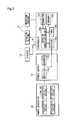
- Fig. 3 is a block diagram showing the electric configuration of the remote controller 1 in a functionally conceptual manner. As shown in Fig. 3 , the power generator 14, the power supply 15 and the controller 16 are electrically connected. Also, the plurality of operation buttons 12 and the display 13 are electrically connected to the controller 16.
- the power generator 14 includes a plurality of piezoelectric devices (power generation devices) 14e, 14f (described later) that generates an electromotive force when deformed.
- the specific structure of the piezoelectric devices 14e, 14f is described later.
- the power supply 15 includes a rectifier 15a and a recharger 15b.
- the rectifier 15a including a bridge rectifier circuit (not shown), rectifies power from the power generator 14.
- the recharger 15b including a capacitor or secondary battery (not shown), is charged with power rectified by the rectifier 15a and supplies the power to the controller 16 when the charged power exceeds a predetermined amount.
- the controller 16 includes a detector 16a, a timer 16b, an operation identification unit 16c, a memory 16d and a transmitter 16e.
- the detector 16a is an operation detection means for detecting when any of the operation buttons 12 is operated, by detecting current output from the rectifier 15a to detect when any of the piezoelectric devices 14e, 14f is pressed.
- the timer 16b is a time measurement means for measuring time under the control of the operation identification unit 16c.
- the operation identification unit 16c is an operation identification means for identifying what operation has been performed on the operation buttons 12, based on which of the operation buttons 12 has been pushed by a user and the time that has been measured by the timer 16b.
- the memory 16d is a storage means for storing in nonvolatile manner information necessary for controlling the controller 16. Specifically, the memory 16d previously stores an operation identification table for identifying an operation based on the operation type having been specified by the user and the operation button 12 having been pushed by the user.
- the transmitter 16e is a signal output means for wirelessly transmitting an operation signal corresponding to the result of identification by the operation identification unit 16c, using any appropriate transmission scheme.
- the remote controller 1 may include various parts and the like as implemented in known remote controllers, however the description of those parts and the like is omitted.
- the operation panel 11 is mounted on the main body 10 such that the operation panel 11 can be rotated with respect to the main body 10 by an operation force applied to any of the operation buttons 12.
- the operation panel 11 can be rotated with respect to the main body 10 about a rotating shaft 11 a provided along at least one side (a side to the left of Fig. 2 in this embodiment) of the sides of the operation panel 11.
- the rotating shaft 11a is secured to the operation panel 11 penetrating through the inside of one side of the operation panel 11. Both ends in the axis direction of the rotating shaft 11a are rotatably fitted into shaft holes provided at positions in the main body 10 corresponding to the ends, allowing the operation panel 11 to be rotated about the rotating shaft 11a.
- a spring 11b is secured to a corner formed by the side of the operation panel 11 along which the rotating shaft 11a is provided and the main body 10.
- the spring 11b is secured to both the operation panel 11 and the main body 10, holding the operation panel 11 at a predetermined angle with respect to the main body 10.
- the operation panel 11 when no operation force is applied to any of the operation buttons 12 (hereinafter referred to as "in non-operated state"), the operation panel 11 is placed at an angle of ⁇ (>0) with respect to another side surface of the main body 10 opposite to the operation panel 11 (hereinafter; a bottom surface 10a in the first embodiment and a second embodiment described later) at which the operation panel 11 is not in approximately parallel with the bottom surface 10a (hereinafter referred to as "in non-rotating state").
- the angle ⁇ is determined by adjusting the number of layers of the piezoelectric devices 14e, 14f described later of a piezoelectric unit 14a described later (or the number of layers of pair-modules 14b) such that the piezoelectric devices 14e, 14f are pressed to be deformed, generating resistance force and then can hardly rotate for more at an angle of ⁇ ( ⁇ 0).
- the power generator 14 can be pressed with a large force due to the principle of leverage, particularly at a position near the rotating shaft 11a. Furthermore, since the power generator 14 is placed at a position near the rotating shaft 11a and the operation buttons 12 are placed at a position near a side of the sides of the operation panel 11 opposite to the rotating shaft 11a, pressing down of any of the operation buttons 12 is performed at a position far from the rotating shaft 11a, which can provide a large rotation moment about the rotating shaft 11a.
- buttons 12 can provide a large pressing force to be applied to the power generator 14, deforming the piezoelectric devices 14e, 14f of the power generator 14 with a larger force, which can provide a large electromotive force.
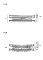
- Fig. 4 is an enlarged view of the power generator 14 and its surroundings in Fig. 2 when the operation panel 11 is in non-rotating state.
- Fig. 5 is an enlarged view of the power generator 14 and its surroundings in Fig. 2 when the operation panel 11 is in rotating state (It should be noted that, in Figs. 4 and 5 and Figs. 11 and 12 to be referred to later, the operation panel 11 is shown with the angle and thickness calculated for effect for the purpose of illustration).
- Fig. 6 is a longitudinal sectional view showing one pair-module in non-deformed state.
- Fig. 7 is a longitudinal sectional view showing one pair-module in deformed state.
- Fig. 8 is a perspective view of the lower piezoelectric module in Fig. 6 seen from above.
- Fig. 8 is a perspective view of the lower piezoelectric module in Fig. 6 seen from below.
- the power generator 14 includes a plurality of piezoelectric units 14a installed adjacent to each other in a direction perpendicular to the rotating shaft 11a of the operation panel 11 (in an adjacent installation direction shown in Figs. 4 and 5 ). Also, the piezoelectric units 14a are installed adjacent to each other in a direction in parallel with the rotating shaft 11a of the operation panel 11 (in a direction perpendicular to the above-mentioned adjacent installation direction).
- Each piezoelectric unit 14a is formed by layering a plurality of pair-modules 14b shown in Figs. 6 and 7 . Furthermore, each pair-module 14b is formed by layering a pair of piezoelectric modules 14c. As shown in Figs. 6 to 9 , each piezoelectric module 14c includes a diaphragm 14d, a pair of piezoelectric devices 14e, 14f, a central spacer 14g and a perimeter spacer 14h.
- the diaphragm 14d is a support for stressing the piezoelectric devices 14e, 14f and also is a reinforcement for improving fracture strength of the piezoelectric devices 14e, 14f, which is formed of a metal plate having flexibility and durability.
- the diaphragm 14d may be formed of any appropriate material, and, for example, may be formed of stainless thin plate.
- the diaphragm 14d may have any appropriate planar shape, and, preferably, is uniformly deformed by an external force. In the first embodiment, the planar shape of the diaphragm 14d is a circular shape.
- the pair of piezoelectric devices 14e, 14f generates electricity when deformed by pressure, formed of a piezoelectric ceramic, such as barium titanate or zirconia, or a piezoelectric monocrystalline, such as lithium tantalate (LiTaO 3 ), for example.
- the piezoelectric devices 14e, 14f are formed into a thin plate in the same shape as that of the diaphragm 14d and one size smaller than the diaphragm 14d.
- the piezoelectric devices 14e, 14f are secured to both side surfaces of the diaphragm 14d with an adhesive or the like.
- the piezoelectric devices 14e, 14f may have any appropriate planar shape, and, preferably, have a planar shape similar to that of the diaphragm 14d.
- the planar shape of the piezoelectric devices 14e, 14f is a circular shape with a diameter smaller than that of the diaphragm 14d.
- the piezoelectric devices 14e, 14f may be placed at any appropriate position in planar direction with respect to the diaphragm 14d.
- the piezoelectric devices 14e, 14f are placed in planar direction at the center of the diaphragm 14d because the amount of deformation will be largest at the center of the diaphragm 14d in planar direction.
- the piezoelectric devices 14e, 14f are placed at a position concentric with the diaphragm 14d.
- the piezoelectric devices 14e, 14f include a positive terminal on one surface and a negative terminal on the other surface. A positive lead connected to the positive terminal and a negative lead connected to the negative terminal are pulled out and connected to the rectifier 15a to provide power to the rectifier 15a.
- the central spacer 14g is a transfer member for transferring deformation of piezoelectric devices 14e, 14f of one piezoelectric module 14c to piezoelectric devices 14e, 14f of the other piezoelectric module 14c adjacent to the one piezoelectric module 14c and also maintains a constant distance between the adjacent pairs of piezoelectric devices 14e, 14f.
- the central spacer 14g is secured to one of the pair of piezoelectric devices 14e, 14f secured to the diaphragm 14d (the piezoelectric device 14f in this embodiment) and placed near the center of the piezoelectric device 14f and secured to the piezoelectric device 14f with an adhesive or the like.
- the perimeter spacer 14h maintains a constant distance between the adjacent piezoelectric modules 14c.
- the perimeter spacer 14h is secured to the perimeter of the diaphragm 14d surrounding the other of the pair of piezoelectric devices 14e, 14f secured to the diaphragm 14d (the piezoelectric device 14e in this embodiment) and is formed thick so as to project more outwardly than the piezoelectric device 14e.
- the perimeter spacer 14h may have any appropriate shape that surrounds the piezoelectric device 14e.
- the perimeter spacer 14h may be a circular body placed concentric with the diaphragm 14d. However, the perimeter spacer 14h may have another shape.
- the perimeter spacer 14h may be a plurality of columnar bodies placed along the perimeter surrounding the piezoelectric device 14e.
- the columnar bodies of the perimeter spacer 14h are preferably placed at three positions corresponding to the corners of an equilateral triangle with the centroid placed at the center of the diaphragm 14d in planar direction.
- the columnar bodies may be placed at three or more positions.
- Each pair-module 14b is formed by layering the pair of piezoelectric modules 14c each formed as described above. Specifically, as shown in Figs. 6 and 7 , each pair-module 14b is formed by stacking the pair of piezoelectric modules 14c such that the central spacer 14g of the one piezoelectric module 14c and the central spacer 14g of the other piezoelectric module 14c adjacent to the one piezoelectric module 14c are in contact with each other on the same axis. In the pair-module 14b, the piezoelectric device 14e of the one piezoelectric module 14c is connected to the piezoelectric device 14f of the other piezoelectric module 14c with the central spacers 14g in between. So, as shown in Fig.
- the piezoelectric unit 14a is formed by layering a plurality of the pair-modules 14b each formed as described above. Specifically, as shown in Figs. 4 and 5 , the pair-modules 14b are layered such that the perimeter spacer 14h of each pair-module 14b is in contact with another perimeter spacer 14h adjacent to the pair-module 14b. In this structure, when the piezoelectric devices 14e, 14f of each pair-module 14b are deformed, the diaphragm 14d to which the piezoelectric devices 14e, 14f are secured is also deformed, causing the perimeter spacer 14h secured to the diaphragm 14d to move in the vertical direction of the figure.
- This movement causes the perimeter spacer 14h of another pair-module 14b adjacent to the pair-module 14b to be pressed, which causes the diaphragm 14d to which the perimeter spacer 14h of the another pair-module 14b is secured, to be deformed, causing the piezoelectric devices 14e, 14f secured to this diaphragm 14d, to be deformed.
- deformation of one pair-module 14b can be transferred to another pair module 14b.
- the distance between the piezoelectric devices 14e, 14f positioned outside one pair-module 14b and the piezoelectric devices 14e, 14f positioned outside another pair-module 14b adjacent to the one pair-module 14b is maintained constant by perimeter spacers 14h, which prevents these two piezoelectric devices 14e, 14f from being in contact with each other.
- the central spacers 14g opposite to each other and the perimeter spacers 14h opposite to each other may be bonded to each other so as not to be misaligned.
- the operation panel 11 in non-rotating state, the operation panel 11 is placed at an angle of ⁇ (>0) with respect to the bottom surface 10a at which the operation panel 11 is not in approximately parallel with the bottom surface 10a, and in rotating state, the operation panel 11 is placed at an angle of ⁇ ( ⁇ 0) at which the operation panel 11 is in approximately parallel with the bottom surface 10a.
- the operation panel 11 when the operation panel 11 is in non-rotating state, the operation panel 11 has a height with respect to the bottom surface 10a that gradually increases from a height h1 at a position near the rotating shaft 11a to a height h2 at a position far from the rotating shaft 11a (h1 ⁇ h2), and, when the operation panel 11 is in rotating state, the height is approximately constant between those positions (h1 ⁇ h2).
- the number of layers of the piezoelectric devices 14e, 14f of the plurality of piezoelectric units 14a is gradually increased from a position near the rotating shaft 11a of the operation panel 11 to a position far from the rotating shaft 11a.
- the number of layers of the piezoelectric devices 14e, 14f of the piezoelectric units 14a is determined such that N1 ⁇ Nn, where N1 is the number of layers of the piezoelectric devices 14e, 14f of a piezoelectric unit 14a placed at the nearest position from the rotating shaft 11a, and Nn is the number of layers of the piezoelectric devices 14e, 14f of a piezoelectric unit 14a placed at the farthest position from the rotating shaft 11a
- the rate of increase from N1 to Nn may be set in any appropriate way.
- the number of layers of the piezoelectric devices 14e, 14f may be incremented by one, or may be increased by a given constant number of layers, or may be intermittently or irregularly increased.
- the piezoelectric devices 14e, 14f at a position near the rotating shaft 11a can be deformed by a large pressing force due to the principle of leverage, as shown in Fig. 5 , to provide a large electromotive force.
- the piezoelectric devices 14e, 14f at a position far from the rotating shaft 11a can be deformed by a larger pressing force than that at the position near the rotating shaft 11a due to larger number of layers of the piezoelectric devices 14e, 14f of the piezoelectric unit 14a, to provide a large electromotive force.
- the piezoelectric devices 14e, 14f between the positions near and far from the rotating shaft 11a can be deformed by a large pressing force due to the principle of leverage and the larger number of layers of the piezoelectric devices 14e, 14f of the piezoelectric unit 14a, to provide a large electromotive force.
- a large electromotive force can be obtained across the power generator 14.
- Fig. 10 is a control flowchart of the controller 16.
- step is abbreviated as "S.”
- S electromotive force
- the piezoelectric devices 14e, 14f are deformed to generate an electromotive force (hereinafter referred to as a first electromotive force), the first electromotive force being rectified by the rectifier 15a and charged into the recharger 15b.
- the operation identification unit 16c of the controller 16 monitors the output of the detector 16a (SA1).
- the operation identification unit 16c determines that any of the pairs of the piezoelectric devices 14e, 14f are pressed and then determines that any of the operation buttons 12 is operated, then starts measuring time using the timer 16b (SA2).
- the piezoelectric devices 14e, 14f are deformed to return to the initial state, again generating an electromotive force (hereinafter referred to as a second electromotive force), the second electromotive force being rectified by the rectifier 15a and charged into the recharger 15b.
- the operation identification unit 16c of the controller 16 monitors the output of the detector 16a (SA3).
- the operation identification unit 16c determines that any of the pairs of the piezoelectric devices 14e, 14f are pressed and then determines that any of the operation buttons 12 is operated, then stops measuring time using the timer 16b (SA2) and obtains the elapsed time from SA2 to that point in time (i.e., the time interval from when the first electromotive force was generated until when the second electromotive force was generated) (SA4).
- the operation identification unit 16c determines that a user operation type is 1 (SA6) if the elapsed time exceeds a predetermined time To (SA5, Yes) or determines that the user operation type is 2 (SA7) if the elapsed time is less than the predetermined time To (SA5, No). Then, based on this result of determination and the operation button 12 having been pressed down, detected by a known scheme when any of the operation buttons 12 was pressed down by the user at SA1, the operation identification unit 16c refers to the operation identification table stored in the memory 16d and identifies the operation having been performed by the user.
- the operation identification unit 16c identifies the operation. Then, the operation identification unit 16c generates an operation signal for performing the identified operation, in a predefined format, and outputs the operation signal through the transmitter 16e (SA8). According to this control, two types of operations can be input even through an operation performed on one operation button 12 depending on the duration from when the operation button 12 is pressed down until when the operation button 12 is released, which enables two times the number of operations with respect to the number of the operation buttons 12.
- control by the controller 16 as described above and the outputting of the operation signal by the transmitter 16e can be performed using successively the power generated by the power generator 14 and charged in the recharger 15b, which eliminates the need for providing to the remote controller 1 a power supply (e.g., a battery) in addition to the power generator 14.
- a power supply e.g., a battery
- a known power supply such as a battery
- a plurality of piezoelectric units each include the power generation devices the number of layers of which is the same as each other, and, in each piezoelectric unit, the piezoelectric devices can be pressed down with a pressing plate placed inside a main body such that the pressing plate is in approximately parallel with another side surface of the main body opposite to the operation panel whether or not an operation force is applied to an operation means.
- the second embodiment has a configuration that is approximately the same as that of the first embodiment unless otherwise stated, and, for this configuration, the same reference numerals and/or component names as used for the first embodiment are appropriately used and the description is omitted.
- Fig. 11 is an enlarged view of a power generator and its surroundings in accordance with the second embodiment when an operation panel 11 is in non-rotating state.
- Fig. 12 is an enlarged view of the power generator and its surroundings when the operation panel 11 is in rotating state.
- a plurality of piezoelectric units 14a of a power generator 14 provided in a remote controller 2 in accordance with the second embodiment each include the same number of piezoelectric devices 14e, 14f (the same number of pair-modules 14b) that are layered. Accordingly, regardless of the distance from a rotating shaft 11a, the distance from a bottom surface 10a to the top of the piezoelectric units 14a is constant.
- the pressing plate 20 is a plate-like body having an area approximately corresponding to a plane on which the piezoelectric units 14a are adjacently installed, and is placed inside a main body 10 so as to be in approximately parallel with the bottom surface 10a.
- the pressing plate 20 is connected to the operation panel 11 by a plurality of connecting rods 21.
- the plurality of connecting rods 21 each have a length corresponding to the distance between the operation panel 11 and the pressing plate 20.
- the connecting rods 21 are formed so as to have a length that increases from a position near the rotating shaft 11a of the operation panel 11 to a position far from the rotating shaft 11a.
- the pressing plate 20 presses the piezoelectric devices 14e, 14f of the plurality of piezoelectric units 14a by approximately the same force at the same time. Accordingly, a large pressing force due to the principle of leverage at a position near the rotating shaft 11a is distributed and applied to the piezoelectric units 14a by the pressing plate 20 to deform the piezoelectric devices 14e, 14f by a larger force, which can provide a large electromotive force.
- an operation panel includes a first operation panel and a second operation panel.
- the first operation panel can be rotated with respect to a main body about a first rotating shaft provided along at least one side of the sides of the first operation panel.
- the second operation panel can be rotated with respect to the main body about a second rotating shaft provided along at least one side of the sides of the second operation panel.
- the side along which the second rotating shaft of the second operation panel is provided is a side of the sides of the second operation panel that is in approximately parallel with the first rotating shaft and is the farthest from the first rotating shaft.
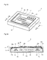
- Fig. 13 is a general perspective view of a remote controller in accordance with the third embodiment.
- Fig. 14 is a cross-sectional view taken in the direction indicated by the arrows B-B in Fig. 13 .
- Fig. 15 is a cross-sectional view taken in the direction indicated by the arrows C-C in Fig. 13 .
- an operation panel 11 of a remote controller 3 in accordance with the third embodiment is divided into a first operation panel 30 and a second operation panel 31.
- the first operation panel 30 and the second operation panel 31 are formed of a metal or resin plate-like body as with the operation panel 11 in the first embodiment and include a plurality of plate-like operation buttons 12 in the form of a membrane switch, touch sensor, touch panel or the like and a display 13 in the form of a liquid crystal panel, implemented on their outer surfaces (however, the display 13 is provided only on the first operation panel 30).
- the operation buttons 12 provided on the first operation panel 30 are referred to as first operation buttons 12a
- the operation buttons 12 provided on the second operation panel 31 are referred to as second operation buttons 12b.
- the first operation panel 30 is formed to have an approximately U-like planar shape.
- the second operation panel 31 is formed to have an approximately I-like planar shape.
- the first operation panel 30 and the second operation panel 31 are fitted to each other at a position shown in Fig. 13 to form an operation panel surface approximately rectangular in planar direction.
- the first operation panel 30 can be rotated with respect to a main body 10 about a first rotating shaft 30a provided along at least one side (a side to the left of Fig. 14 in this embodiment) of the sides of the first operation panel 30.
- the second operation panel 31 can be rotated with respect to the main body 10 about a second rotating shaft 31a provided along at least one side (a side to the right of Fig. 15 in this embodiment) of the sides of the second operation panel 31.
- a rotatable structure provided by the first rotating shaft 30a and the second rotating shaft 31a is similar to the rotatable structure provided by the rotating shaft 11a in the first embodiment, so the description is omitted.
- the first operation panel 30 When no operation force is applied to any of the first operation buttons 12 (hereinafter referred to as “in non-operated state”), the first operation panel 30 is placed at an angle of ⁇ (>0) with respect to another side surface of the main body 10 opposite to the first operation panel 30 (hereinafter; a bottom surface 10a in the third embodiment) at which the first operation panel 30 is not in approximately parallel with the bottom surface 10a (hereinafter referred to as "in non-rotating state").
- the second operation panel 31 When no operation force is applied to any of the second operation buttons 12b (hereinafter referred to as "in non-operated state"), the second operation panel 31 is placed at an angle of ⁇ (>0) with respect to another side surface of the main body 10 opposite to the second operation panel 31 (hereinafter; the bottom surface 10a in the third embodiment) at which the second operation panel 31 is not in approximately parallel with the bottom surface 10a (hereinafter referred to as "in non-rotating state").
- power generators 14 includes a first power generator 14i and a second power generator 14j.
- the first power generator 14i is placed at a position near the first rotating shaft 30a.
- the second power generator 14j is placed at a position near the second rotating shaft 31 a.
- the first power generator 14i and the second power generator 14j each include a plurality of piezoelectric units 14a. Piezoelectric devices 14e, 14f of the piezoelectric units 14a generate an electromotive force that is provided to a common power supply 15, then a control similar to that in the first embodiment is performed.
- the number of layers of the piezoelectric devices 14e, 14f of the plurality of piezoelectric units 14a provided in the first power generator 14i is gradually increased from a position near the first rotating shaft 30a to a position far from the first rotating shaft 30a.
- the number of layers of the piezoelectric devices 14e, 14f of the plurality of piezoelectric units 14a provided in the second power generator 14j is gradually increased from a position near the second rotating shaft 31a to a position far from the second rotating shaft 31a.
- the first power generator 14i and the second power generator 14j each can provide a larger electromotive force as with the first embodiment.
- a fourth embodiment is described.
- a first extension plate is provided on a first operation panel at a position far from a first rotating shaft of the first operation panel
- a second extension plate is provided on a second operation panel at a position far from a second rotating shaft of the second operation panel.
- the first extension plate and the second extension plate have a shape such that the first extension plate and the second extension plate do not interfere with each other.
- the fourth embodiment has a configuration that is approximately the same as that of the third embodiment unless otherwise stated, and, for this configuration, the same reference numerals and/or component names as used for the third embodiment are appropriately used and the description is omitted.
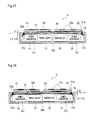
- Fig. 16 is a general perspective view of a remote controller in accordance with the fourth embodiment.
- Fig. 17 is a cross-sectional view taken in the direction indicated by the arrows D-D in Fig. 16 .
- Fig. 18 is a cross-sectional view taken in the direction indicated by the arrows E-E in Fig. 16 .
- a first extension plate 40 is provided on the outer surface of a first operation panel 30, and a second extension plate 41 is provided on the outer surface of a second operation panel 31.
- the first operation panel 30 and the second operation panel 31 are formed of a metal or resin plate-like body
- the first extension plate 40 and the second extension plate 41 are formed of a metal or resin plate-like body as with the operation panel 11 in the first embodiment and include a plurality of plate-like operation buttons 12 in the form of a membrane switch, touch sensor, touch panel or the like, implemented on their outer surfaces (however, the display 13 is omitted).
- the operation buttons 12 provided on the first extension plate 40 are referred to as first operation buttons 12a
- the operation buttons 12 provided on the second extension plate 41 are referred to as second operation buttons 12b.
- the first extension plate 40 is provided on the first operation panel 30 at a position far from a first rotating shaft 30a. So, pressing down any of the first operation buttons 12a enables pressing down of the first operation panel 30 at a position far from the first rotating shaft 30a, providing an effect of the principle of leverage.
- the second extension plate 41 is provided on the second operation panel 31 at a position far from a second rotating shaft 31 a. So, pressing down any of the second operation buttons 12b enables pressing down of the second operation panel 31 at a position far from the second rotating shaft 31a, providing an effect of the principle of leverage.
- pressing down the first extension plate 40 at any position enables pressing down of the first operation panel 30 at a position far from the first rotating shaft 30a, so the first operation buttons 12a may be placed at any position on the outer surface of the first extension plate 40.
- pressing down the second extension plate 41 at any position enables pressing down of the second operation panel 31 at a position far from the second rotating shaft 31a, so the second operation buttons 12b may be placed at any position on the outer surface of the second extension plate 41.
- an area in which the first operation buttons 12a and the second operation buttons 12b may be placed becomes wider, which enables effective utilization of the operation panel surface and increase in freedom of placing the first operation buttons 12a and the second operation buttons 12b.
- the first extension plate 40 and the second extension plate 41 are placed at approximately the same position in height direction, they should be placed so as not to interfere with each other. Accordingly, in the fourth embodiment, the first extension plate 40 has a planar shape that is a rectangular shape having an area approximately equal to the area of one-half far from the first rotating shaft 30a of the operation panel surface formed of the first operation panel 30 and the second operation panel 31, and the second extension plate 41 has a planar shape that is a rectangular shape having an area approximately equal to the area of one-half far from the second rotating shaft 31a of the operation panel surface formed of the first operation panel 30 and the second operation panel 31.
- the combined area of the first extension plate 40 and the second extension plate 41 is approximately the same as that of the operation panel surface formed of the first operation panel 30 and the second operation panel 31, enabling effective utilization of the operation panel surface.
- the position of the first operation panel 30 after the rotation is set to a position such that the first extension plate 40 does not interfere with the main body 10 and the second operation panel 31 rather than a position such that the first operation panel 30 is in approximately parallel with the bottom surface 10a.
- the position of the second operation panel 31 after the rotation is set to a position such that the second extension plate 41 does not interfere with the main body 10 and the first operation panel 30 rather than a position such that the second operation panel 31 is in approximately parallel with the bottom surface 10a.
- a position can be adjusted by adjusting the number of layers of piezoelectric devices 14e, 14f of piezoelectric unit 14a (or the number of layers of pair-modules 14b).
- the above-described interference may be avoided by connecting the first extension plate 40 to the first operation panel 30 with a space in between or connecting the second extension plate 41 to the second operation panel 31 with a space in between to place the first extension plate 40 or the second extension plate 41 to a position more outside than the shown position.
- a problem to be solved by the invention and an advantageous effect of the invention are not limited to those described above.
- the invention may also solve a problem not described above or achieve an advantageous effect not described above.
- the invention may also solve only a part of a problem described above or achieve only a part of an advantageous effect described above.
- the electric apparatus may be configured as a mobile phone, an electric apparatus to be built in a building including a lighting means for lighting a floor or staircase, a lighting means to be built in a shoe or bicycle pedal for lighting around the shoe or bicycle, a communication means to be built in a shoe or bicycle pedal for performing communication between a shoe or bicycle and an external apparatus, and the like.
- the electric apparatus to be built in a building may be configured by, for example, installing an electric apparatus in accordance with the invention into the interior of a floor or staircase and exposing an operation panel to the outside as a floor panel or stair tread so that, when a user walks on the floor or staircase, the operation panel is pressed to generate an electromotive force that can activate a light placed around the floor or staircase.
- the electric apparatus to be built in a shoe or bicycle may be configured by, for example, installing an electric apparatus in accordance with the invention into the interior of a shoe or bicycle pedal and exposing an operation panel to the outside as a sole of the shoe or a tread of the bicycle pedal so that, when a user presses the shoe or the pedal, the operation panel is pressed to generate an electromotive force.
- the electric apparatus may be configured to be a remote controller that emits light by activating a lighting means, such as an LED, provided to be exposed to the outside of the main body when a user grips the remote controller.
- a lighting means such as an LED
- the placement angle and rotation angle of the operation panel may be an angle other than the angle used in the above embodiment.
- the operation panel may be in approximately parallel with the bottom surface in non-rotating state and not in parallel with the bottom surface in rotating state.
- the operation panel may be not in parallel with the bottom surface in both non-rotating state and rotating state, and the angle of the operation panel with respect to the bottom surface may be different between non-rotating state and rotating state.
Landscapes
- General Electrical Machinery Utilizing Piezoelectricity, Electrostriction Or Magnetostriction (AREA)
Priority Applications (1)
| Application Number | Priority Date | Filing Date | Title |
|---|---|---|---|
| EP13199423.8A EP2793388B1 (de) | 2009-11-11 | 2009-11-11 | Elektrogerät mit energieerzeugungsfunktion |
Applications Claiming Priority (1)
| Application Number | Priority Date | Filing Date | Title |
|---|---|---|---|
| PCT/JP2009/006027 WO2011058602A1 (ja) | 2009-11-11 | 2009-11-11 | 発電機能付き電気機器 |
Related Child Applications (2)
| Application Number | Title | Priority Date | Filing Date |
|---|---|---|---|
| EP13199423.8A Division EP2793388B1 (de) | 2009-11-11 | 2009-11-11 | Elektrogerät mit energieerzeugungsfunktion |
| EP13199423.8A Division-Into EP2793388B1 (de) | 2009-11-11 | 2009-11-11 | Elektrogerät mit energieerzeugungsfunktion |
Publications (3)
| Publication Number | Publication Date |
|---|---|
| EP2501031A1 true EP2501031A1 (de) | 2012-09-19 |
| EP2501031A4 EP2501031A4 (de) | 2013-07-10 |
| EP2501031B1 EP2501031B1 (de) | 2017-02-15 |
Family
ID=43991283
Family Applications (2)
| Application Number | Title | Priority Date | Filing Date |
|---|---|---|---|
| EP13199423.8A Not-in-force EP2793388B1 (de) | 2009-11-11 | 2009-11-11 | Elektrogerät mit energieerzeugungsfunktion |
| EP09851237.9A Not-in-force EP2501031B1 (de) | 2009-11-11 | 2009-11-11 | Elektrogerät mit energieerzeugungsfunktion |
Family Applications Before (1)
| Application Number | Title | Priority Date | Filing Date |
|---|---|---|---|
| EP13199423.8A Not-in-force EP2793388B1 (de) | 2009-11-11 | 2009-11-11 | Elektrogerät mit energieerzeugungsfunktion |
Country Status (4)
| Country | Link |
|---|---|
| US (1) | US8686620B2 (de) |
| EP (2) | EP2793388B1 (de) |
| JP (1) | JP5458417B2 (de) |
| WO (1) | WO2011058602A1 (de) |
Cited By (5)
| Publication number | Priority date | Publication date | Assignee | Title |
|---|---|---|---|---|
| WO2014173817A1 (de) * | 2013-04-25 | 2014-10-30 | Zumtobel Lighting Gmbh | Energieautarkes bedienelement für ein steuerbares gerät |
| WO2015059418A1 (fr) * | 2013-10-25 | 2015-04-30 | Commissariat à l'énergie atomique et aux énergies alternatives | Convertisseur d'energie a recuperer et generateur d'electricite |
| EP3070832A4 (de) * | 2013-11-12 | 2017-08-23 | Murata Manufacturing Co., Ltd. | Stromerzeugungsvorrichtung |
| CN110344658A (zh) * | 2019-06-24 | 2019-10-18 | 武开阔 | 一种自供电汽车钥匙 |
| CN111082702A (zh) * | 2019-12-31 | 2020-04-28 | 石河子大学 | 一种遥控装置、压电式激光笔及遥控系统 |
Families Citing this family (16)
| Publication number | Priority date | Publication date | Assignee | Title |
|---|---|---|---|---|
| US9218032B2 (en) * | 2012-08-09 | 2015-12-22 | Qualcomm Incorporated | Apparatus and method for charging a mobile device |
| CN103124148A (zh) * | 2013-01-30 | 2013-05-29 | 东南大学 | 超声波电机遥控器 |
| JP5652490B2 (ja) * | 2013-03-27 | 2015-01-14 | Toto株式会社 | リモコン装置 |
| JP5652491B2 (ja) * | 2013-03-27 | 2015-01-14 | Toto株式会社 | リモコン装置 |
| JP6344837B2 (ja) * | 2014-05-18 | 2018-06-20 | 俊樹 小野 | 電力発電装置、情報入力装置、並びに情報入力機器保護装置 |
| CN104506085B (zh) * | 2015-01-07 | 2017-01-04 | 浙江师范大学 | 一种自供电遥控器 |
| CN104506084B (zh) * | 2015-01-07 | 2017-01-04 | 浙江师范大学 | 一种微小型环保遥控器 |
| CN104506082B (zh) * | 2015-01-07 | 2017-01-11 | 浙江师范大学 | 一种无电池遥控器 |
| EP3285390B1 (de) * | 2015-04-13 | 2021-03-24 | Murata Manufacturing Co., Ltd. | Piezoelektrischer stromgenerator |
| JP2016218622A (ja) * | 2015-05-18 | 2016-12-22 | 株式会社リコー | 誘導装置、及び誘導システム |
| CN105119522A (zh) * | 2015-09-02 | 2015-12-02 | 北京印刷学院 | 铁路运营远程监测冲击震动压电变换质能转换装置 |
| DE102016203520A1 (de) * | 2016-03-03 | 2017-09-07 | Volkswagen Aktiengesellschaft | Gehäuse, beispielsweise für eine Funkfernbedienung oder einen Fahrzeugschlüssel und Funkfernbedienung |
| JP2017175751A (ja) * | 2016-03-23 | 2017-09-28 | 国立大学法人東北大学 | 振動発電素子 |
| US12095639B2 (en) | 2019-10-23 | 2024-09-17 | Aryaka Networks, Inc. | Method, device and system for improving performance of point anomaly based data pattern change detection associated with network entity features in a cloud-based application acceleration as a service environment |
| US12220629B2 (en) * | 2020-04-07 | 2025-02-11 | Sony Interactive Entertainment Inc. | Operation device and operation system |
| US20240022185A1 (en) * | 2021-04-15 | 2024-01-18 | Wenjing Wu | Self-powered device |
Family Cites Families (14)
| Publication number | Priority date | Publication date | Assignee | Title |
|---|---|---|---|---|
| JPS60102776A (ja) * | 1983-11-09 | 1985-06-06 | Toshio Sugita | 通行人や走行車両による路面圧力をエネルギ−源とする圧電素子発光装置 |
| GB9000932D0 (en) * | 1990-01-16 | 1990-03-14 | Maygay Machines | Machine controls |
| JP3170965B2 (ja) | 1993-08-04 | 2001-05-28 | セイコーエプソン株式会社 | 発電機および携帯用機器 |
| JP3951438B2 (ja) | 1998-04-23 | 2007-08-01 | 株式会社村田製作所 | 圧電型風力発電機 |
| FR2802731B1 (fr) * | 1999-12-16 | 2002-01-25 | Schneider Electric Ind Sa | Dispositif autonome de commande a distance, appareil et installation electrique comportant un tel dispositif |
| JP3616386B2 (ja) * | 2002-12-17 | 2005-02-02 | 太平洋セメント株式会社 | 信号発信装置 |
| DE10305026A1 (de) * | 2003-02-07 | 2004-08-19 | Ceram Tec Ag Innovative Ceramic Engineering | Einrichtung zur Versorgung tragbarer Geräte mit elektrischer Energie |
| JP2006048302A (ja) * | 2004-08-03 | 2006-02-16 | Sony Corp | 圧電複合装置、その製造方法、その取扱方法、その制御方法、入出力装置及び電子機器 |
| JP4504292B2 (ja) * | 2005-09-28 | 2010-07-14 | 浩平 速水 | 発電装置 |
| JP2007143353A (ja) * | 2005-11-22 | 2007-06-07 | Matsushita Electric Ind Co Ltd | 発電システム並びにこれを応用した電子機器 |
| JP2008140206A (ja) * | 2006-12-04 | 2008-06-19 | Seiko Epson Corp | 発電入力装置及び電子機器 |
| CN101855820B (zh) * | 2007-11-13 | 2013-07-17 | 速水浩平 | 电力产生单元 |
| JP2009225622A (ja) | 2008-03-18 | 2009-10-01 | Nec Corp | 携帯型通信装置 |
| JP5530155B2 (ja) * | 2009-11-11 | 2014-06-25 | ルネサスエレクトロニクス株式会社 | 発電機能付き手動操作機器、発電機能付き遠隔操作装置 |
-
2009
- 2009-11-11 EP EP13199423.8A patent/EP2793388B1/de not_active Not-in-force
- 2009-11-11 EP EP09851237.9A patent/EP2501031B1/de not_active Not-in-force
- 2009-11-11 WO PCT/JP2009/006027 patent/WO2011058602A1/ja not_active Ceased
- 2009-11-11 JP JP2011540333A patent/JP5458417B2/ja active Active
-
2012
- 2012-05-10 US US13/468,948 patent/US8686620B2/en active Active
Cited By (7)
| Publication number | Priority date | Publication date | Assignee | Title |
|---|---|---|---|---|
| WO2014173817A1 (de) * | 2013-04-25 | 2014-10-30 | Zumtobel Lighting Gmbh | Energieautarkes bedienelement für ein steuerbares gerät |
| WO2015059418A1 (fr) * | 2013-10-25 | 2015-04-30 | Commissariat à l'énergie atomique et aux énergies alternatives | Convertisseur d'energie a recuperer et generateur d'electricite |
| US10205408B2 (en) | 2013-10-25 | 2019-02-12 | Commissariat à l'énergie atomique et aux énergies alternatives | Converter for converting energy to be recovered and electricity generator |
| EP3070832A4 (de) * | 2013-11-12 | 2017-08-23 | Murata Manufacturing Co., Ltd. | Stromerzeugungsvorrichtung |
| CN110344658A (zh) * | 2019-06-24 | 2019-10-18 | 武开阔 | 一种自供电汽车钥匙 |
| CN111082702A (zh) * | 2019-12-31 | 2020-04-28 | 石河子大学 | 一种遥控装置、压电式激光笔及遥控系统 |
| CN111082702B (zh) * | 2019-12-31 | 2021-03-23 | 石河子大学 | 一种遥控装置、压电式激光笔及遥控系统 |
Also Published As
| Publication number | Publication date |
|---|---|
| JP5458417B2 (ja) | 2014-04-02 |
| EP2501031A4 (de) | 2013-07-10 |
| JPWO2011058602A1 (ja) | 2013-03-28 |
| EP2793388A1 (de) | 2014-10-22 |
| US20120248937A1 (en) | 2012-10-04 |
| EP2501031B1 (de) | 2017-02-15 |
| EP2793388B1 (de) | 2017-09-13 |
| US8686620B2 (en) | 2014-04-01 |
| WO2011058602A1 (ja) | 2011-05-19 |
Similar Documents
| Publication | Publication Date | Title |
|---|---|---|
| EP2501031B1 (de) | Elektrogerät mit energieerzeugungsfunktion | |
| EP2209201B1 (de) | Stromerzeugungseinheit | |
| US8508193B2 (en) | Environmentally-powered wireless sensor module | |
| CN103368446B (zh) | 静电发电机及其制备方法和自驱动传感系统 | |
| US20260071773A1 (en) | Thermostat with Detachable Dial Control | |
| JP2003224315A (ja) | 起電装置、電源装置、遠隔操作装置、及び電子機器 | |
| JP5091743B2 (ja) | 無線電力配電システム | |
| CN107246906A (zh) | 能源自给微型电子秤 | |
| JP2008017592A (ja) | 情報表示システム装置 | |
| US9634232B2 (en) | Piezoelectric signal generator | |
| WO2013124767A1 (en) | Energy exciting mechanism for a self-powered switch and method for exciting energy | |
| KR20140012410A (ko) | 터치패널 및 상기 터치패널 충전 방법 | |
| CN212660117U (zh) | 压电马达、触控反馈模组及触控装置 | |
| JP2011193665A (ja) | 発電システム | |
| CN114898660B (zh) | 显示装置以及电子设备 | |
| JP2004350019A (ja) | 発電部を有するスイッチ端末および発電部を有するスイッチ端末の使用方法 | |
| CN205649007U (zh) | 基于压电发电原理的gps鞋 | |
| JP2011250521A (ja) | 発電パネル、及び発電パネルを用いた発電システム | |
| Jawahar et al. | Kicking Yourself Awake: Towards self-powering mats for room-level localization and occupancy detection | |
| JP5786186B2 (ja) | 発電システム | |
| US10461784B2 (en) | Communication apparatus | |
| CN210536318U (zh) | 一种充电器 | |
| JP6539796B1 (ja) | 発電装置及び携帯型パーソナルコンピュータ | |
| CN205809118U (zh) | 一种信息化智能电表装置 | |
| HK1149382B (en) | Power generation unit |
Legal Events
| Date | Code | Title | Description |
|---|---|---|---|
| PUAI | Public reference made under article 153(3) epc to a published international application that has entered the european phase |
Free format text: ORIGINAL CODE: 0009012 |
|
| 17P | Request for examination filed |
Effective date: 20120521 |
|
| AK | Designated contracting states |
Kind code of ref document: A1 Designated state(s): AT BE BG CH CY CZ DE DK EE ES FI FR GB GR HR HU IE IS IT LI LT LU LV MC MK MT NL NO PL PT RO SE SI SK SM TR |
|
| DAX | Request for extension of the european patent (deleted) | ||
| A4 | Supplementary search report drawn up and despatched |
Effective date: 20130610 |
|
| RIC1 | Information provided on ipc code assigned before grant |
Ipc: H02N 2/18 20060101AFI20130604BHEP |
|
| REG | Reference to a national code |
Ref country code: DE Ref legal event code: R079 Ref document number: 602009044268 Country of ref document: DE Free format text: PREVIOUS MAIN CLASS: H02N0002000000 Ipc: H02N0002180000 |
|
| GRAP | Despatch of communication of intention to grant a patent |
Free format text: ORIGINAL CODE: EPIDOSNIGR1 |
|
| RIC1 | Information provided on ipc code assigned before grant |
Ipc: H01L 41/113 20060101ALI20160819BHEP Ipc: H02N 2/18 20060101AFI20160819BHEP |
|
| INTG | Intention to grant announced |
Effective date: 20160913 |
|
| RIN1 | Information on inventor provided before grant (corrected) |
Inventor name: HAYAMIZU, KOHEI |
|
| GRAS | Grant fee paid |
Free format text: ORIGINAL CODE: EPIDOSNIGR3 |
|
| GRAA | (expected) grant |
Free format text: ORIGINAL CODE: 0009210 |
|
| AK | Designated contracting states |
Kind code of ref document: B1 Designated state(s): AT BE BG CH CY CZ DE DK EE ES FI FR GB GR HR HU IE IS IT LI LT LU LV MC MK MT NL NO PL PT RO SE SI SK SM TR |
|
| REG | Reference to a national code |
Ref country code: CH Ref legal event code: EP Ref country code: GB Ref legal event code: FG4D |
|
| REG | Reference to a national code |
Ref country code: IE Ref legal event code: FG4D |
|
| REG | Reference to a national code |
Ref country code: AT Ref legal event code: REF Ref document number: 868402 Country of ref document: AT Kind code of ref document: T Effective date: 20170315 |
|
| REG | Reference to a national code |
Ref country code: DE Ref legal event code: R096 Ref document number: 602009044268 Country of ref document: DE |
|
| REG | Reference to a national code |
Ref country code: NL Ref legal event code: MP Effective date: 20170215 |
|
| REG | Reference to a national code |
Ref country code: LT Ref legal event code: MG4D |
|
| REG | Reference to a national code |
Ref country code: AT Ref legal event code: MK05 Ref document number: 868402 Country of ref document: AT Kind code of ref document: T Effective date: 20170215 |
|
| PG25 | Lapsed in a contracting state [announced via postgrant information from national office to epo] |
Ref country code: FI Free format text: LAPSE BECAUSE OF FAILURE TO SUBMIT A TRANSLATION OF THE DESCRIPTION OR TO PAY THE FEE WITHIN THE PRESCRIBED TIME-LIMIT Effective date: 20170215 Ref country code: HR Free format text: LAPSE BECAUSE OF FAILURE TO SUBMIT A TRANSLATION OF THE DESCRIPTION OR TO PAY THE FEE WITHIN THE PRESCRIBED TIME-LIMIT Effective date: 20170215 Ref country code: LT Free format text: LAPSE BECAUSE OF FAILURE TO SUBMIT A TRANSLATION OF THE DESCRIPTION OR TO PAY THE FEE WITHIN THE PRESCRIBED TIME-LIMIT Effective date: 20170215 Ref country code: GR Free format text: LAPSE BECAUSE OF FAILURE TO SUBMIT A TRANSLATION OF THE DESCRIPTION OR TO PAY THE FEE WITHIN THE PRESCRIBED TIME-LIMIT Effective date: 20170516 Ref country code: NO Free format text: LAPSE BECAUSE OF FAILURE TO SUBMIT A TRANSLATION OF THE DESCRIPTION OR TO PAY THE FEE WITHIN THE PRESCRIBED TIME-LIMIT Effective date: 20170515 |
|
| PG25 | Lapsed in a contracting state [announced via postgrant information from national office to epo] |
Ref country code: AT Free format text: LAPSE BECAUSE OF FAILURE TO SUBMIT A TRANSLATION OF THE DESCRIPTION OR TO PAY THE FEE WITHIN THE PRESCRIBED TIME-LIMIT Effective date: 20170215 Ref country code: ES Free format text: LAPSE BECAUSE OF FAILURE TO SUBMIT A TRANSLATION OF THE DESCRIPTION OR TO PAY THE FEE WITHIN THE PRESCRIBED TIME-LIMIT Effective date: 20170215 Ref country code: NL Free format text: LAPSE BECAUSE OF FAILURE TO SUBMIT A TRANSLATION OF THE DESCRIPTION OR TO PAY THE FEE WITHIN THE PRESCRIBED TIME-LIMIT Effective date: 20170215 Ref country code: SE Free format text: LAPSE BECAUSE OF FAILURE TO SUBMIT A TRANSLATION OF THE DESCRIPTION OR TO PAY THE FEE WITHIN THE PRESCRIBED TIME-LIMIT Effective date: 20170215 Ref country code: LV Free format text: LAPSE BECAUSE OF FAILURE TO SUBMIT A TRANSLATION OF THE DESCRIPTION OR TO PAY THE FEE WITHIN THE PRESCRIBED TIME-LIMIT Effective date: 20170215 Ref country code: BG Free format text: LAPSE BECAUSE OF FAILURE TO SUBMIT A TRANSLATION OF THE DESCRIPTION OR TO PAY THE FEE WITHIN THE PRESCRIBED TIME-LIMIT Effective date: 20170515 Ref country code: PT Free format text: LAPSE BECAUSE OF FAILURE TO SUBMIT A TRANSLATION OF THE DESCRIPTION OR TO PAY THE FEE WITHIN THE PRESCRIBED TIME-LIMIT Effective date: 20170615 |
|
| PG25 | Lapsed in a contracting state [announced via postgrant information from national office to epo] |
Ref country code: CZ Free format text: LAPSE BECAUSE OF FAILURE TO SUBMIT A TRANSLATION OF THE DESCRIPTION OR TO PAY THE FEE WITHIN THE PRESCRIBED TIME-LIMIT Effective date: 20170215 Ref country code: SK Free format text: LAPSE BECAUSE OF FAILURE TO SUBMIT A TRANSLATION OF THE DESCRIPTION OR TO PAY THE FEE WITHIN THE PRESCRIBED TIME-LIMIT Effective date: 20170215 Ref country code: RO Free format text: LAPSE BECAUSE OF FAILURE TO SUBMIT A TRANSLATION OF THE DESCRIPTION OR TO PAY THE FEE WITHIN THE PRESCRIBED TIME-LIMIT Effective date: 20170215 Ref country code: IT Free format text: LAPSE BECAUSE OF FAILURE TO SUBMIT A TRANSLATION OF THE DESCRIPTION OR TO PAY THE FEE WITHIN THE PRESCRIBED TIME-LIMIT Effective date: 20170215 Ref country code: EE Free format text: LAPSE BECAUSE OF FAILURE TO SUBMIT A TRANSLATION OF THE DESCRIPTION OR TO PAY THE FEE WITHIN THE PRESCRIBED TIME-LIMIT Effective date: 20170215 |
|
| REG | Reference to a national code |
Ref country code: DE Ref legal event code: R097 Ref document number: 602009044268 Country of ref document: DE |
|
| PG25 | Lapsed in a contracting state [announced via postgrant information from national office to epo] |
Ref country code: SM Free format text: LAPSE BECAUSE OF FAILURE TO SUBMIT A TRANSLATION OF THE DESCRIPTION OR TO PAY THE FEE WITHIN THE PRESCRIBED TIME-LIMIT Effective date: 20170215 Ref country code: PL Free format text: LAPSE BECAUSE OF FAILURE TO SUBMIT A TRANSLATION OF THE DESCRIPTION OR TO PAY THE FEE WITHIN THE PRESCRIBED TIME-LIMIT Effective date: 20170215 Ref country code: DK Free format text: LAPSE BECAUSE OF FAILURE TO SUBMIT A TRANSLATION OF THE DESCRIPTION OR TO PAY THE FEE WITHIN THE PRESCRIBED TIME-LIMIT Effective date: 20170215 |
|
| PLBE | No opposition filed within time limit |
Free format text: ORIGINAL CODE: 0009261 |
|
| STAA | Information on the status of an ep patent application or granted ep patent |
Free format text: STATUS: NO OPPOSITION FILED WITHIN TIME LIMIT |
|
| 26N | No opposition filed |
Effective date: 20171116 |
|
| PG25 | Lapsed in a contracting state [announced via postgrant information from national office to epo] |
Ref country code: SI Free format text: LAPSE BECAUSE OF FAILURE TO SUBMIT A TRANSLATION OF THE DESCRIPTION OR TO PAY THE FEE WITHIN THE PRESCRIBED TIME-LIMIT Effective date: 20170215 |
|
| PG25 | Lapsed in a contracting state [announced via postgrant information from national office to epo] |
Ref country code: MC Free format text: LAPSE BECAUSE OF FAILURE TO SUBMIT A TRANSLATION OF THE DESCRIPTION OR TO PAY THE FEE WITHIN THE PRESCRIBED TIME-LIMIT Effective date: 20170215 |
|
| GBPC | Gb: european patent ceased through non-payment of renewal fee |
Effective date: 20171111 |
|
| PG25 | Lapsed in a contracting state [announced via postgrant information from national office to epo] |
Ref country code: LI Free format text: LAPSE BECAUSE OF NON-PAYMENT OF DUE FEES Effective date: 20171130 Ref country code: CH Free format text: LAPSE BECAUSE OF NON-PAYMENT OF DUE FEES Effective date: 20171130 |
|
| PG25 | Lapsed in a contracting state [announced via postgrant information from national office to epo] |
Ref country code: LU Free format text: LAPSE BECAUSE OF NON-PAYMENT OF DUE FEES Effective date: 20171111 |
|
| REG | Reference to a national code |
Ref country code: FR Ref legal event code: ST Effective date: 20180731 Ref country code: BE Ref legal event code: MM Effective date: 20171130 |
|
| REG | Reference to a national code |
Ref country code: IE Ref legal event code: MM4A |
|
| PG25 | Lapsed in a contracting state [announced via postgrant information from national office to epo] |
Ref country code: MT Free format text: LAPSE BECAUSE OF NON-PAYMENT OF DUE FEES Effective date: 20171111 |
|
| PG25 | Lapsed in a contracting state [announced via postgrant information from national office to epo] |
Ref country code: FR Free format text: LAPSE BECAUSE OF NON-PAYMENT OF DUE FEES Effective date: 20171130 Ref country code: IE Free format text: LAPSE BECAUSE OF NON-PAYMENT OF DUE FEES Effective date: 20171111 |
|
| PG25 | Lapsed in a contracting state [announced via postgrant information from national office to epo] |
Ref country code: BE Free format text: LAPSE BECAUSE OF NON-PAYMENT OF DUE FEES Effective date: 20171130 Ref country code: GB Free format text: LAPSE BECAUSE OF NON-PAYMENT OF DUE FEES Effective date: 20171111 |
|
| PG25 | Lapsed in a contracting state [announced via postgrant information from national office to epo] |
Ref country code: HU Free format text: LAPSE BECAUSE OF FAILURE TO SUBMIT A TRANSLATION OF THE DESCRIPTION OR TO PAY THE FEE WITHIN THE PRESCRIBED TIME-LIMIT; INVALID AB INITIO Effective date: 20091111 |
|
| PG25 | Lapsed in a contracting state [announced via postgrant information from national office to epo] |
Ref country code: CY Free format text: LAPSE BECAUSE OF NON-PAYMENT OF DUE FEES Effective date: 20170215 |
|
| PG25 | Lapsed in a contracting state [announced via postgrant information from national office to epo] |
Ref country code: MK Free format text: LAPSE BECAUSE OF FAILURE TO SUBMIT A TRANSLATION OF THE DESCRIPTION OR TO PAY THE FEE WITHIN THE PRESCRIBED TIME-LIMIT Effective date: 20170215 |
|
| PGFP | Annual fee paid to national office [announced via postgrant information from national office to epo] |
Ref country code: DE Payment date: 20191125 Year of fee payment: 11 |
|
| PG25 | Lapsed in a contracting state [announced via postgrant information from national office to epo] |
Ref country code: TR Free format text: LAPSE BECAUSE OF FAILURE TO SUBMIT A TRANSLATION OF THE DESCRIPTION OR TO PAY THE FEE WITHIN THE PRESCRIBED TIME-LIMIT Effective date: 20170215 |
|
| PG25 | Lapsed in a contracting state [announced via postgrant information from national office to epo] |
Ref country code: IS Free format text: LAPSE BECAUSE OF FAILURE TO SUBMIT A TRANSLATION OF THE DESCRIPTION OR TO PAY THE FEE WITHIN THE PRESCRIBED TIME-LIMIT Effective date: 20170615 |
|
| REG | Reference to a national code |
Ref country code: DE Ref legal event code: R119 Ref document number: 602009044268 Country of ref document: DE |
|
| PG25 | Lapsed in a contracting state [announced via postgrant information from national office to epo] |
Ref country code: DE Free format text: LAPSE BECAUSE OF NON-PAYMENT OF DUE FEES Effective date: 20210601 |