EP2501060B1 - Optisches Netzwerksystem und WDM-Vorrichtung - Google Patents
Optisches Netzwerksystem und WDM-Vorrichtung Download PDFInfo
- Publication number
- EP2501060B1 EP2501060B1 EP12159448.5A EP12159448A EP2501060B1 EP 2501060 B1 EP2501060 B1 EP 2501060B1 EP 12159448 A EP12159448 A EP 12159448A EP 2501060 B1 EP2501060 B1 EP 2501060B1
- Authority
- EP
- European Patent Office
- Prior art keywords
- redundant
- transmission
- switching device
- reception
- signal
- Prior art date
- Legal status (The legal status is an assumption and is not a legal conclusion. Google has not performed a legal analysis and makes no representation as to the accuracy of the status listed.)
- Active
Links
Images


Classifications
-
- H—ELECTRICITY
- H04—ELECTRIC COMMUNICATION TECHNIQUE
- H04J—MULTIPLEX COMMUNICATION
- H04J3/00—Time-division multiplex systems
- H04J3/02—Details
- H04J3/14—Monitoring arrangements
-
- H—ELECTRICITY
- H04—ELECTRIC COMMUNICATION TECHNIQUE
- H04J—MULTIPLEX COMMUNICATION
- H04J3/00—Time-division multiplex systems
- H04J3/16—Time-division multiplex systems in which the time allocation to individual channels within a transmission cycle is variable, e.g. to accommodate varying complexity of signals, to vary number of channels transmitted
- H04J3/1605—Fixed allocated frame structures
- H04J3/1611—Synchronous digital hierarchy [SDH] or SONET
-
- H—ELECTRICITY
- H04—ELECTRIC COMMUNICATION TECHNIQUE
- H04J—MULTIPLEX COMMUNICATION
- H04J2203/00—Aspects of optical multiplex systems other than those covered by H04J14/05 and H04J14/07
- H04J2203/0001—Provisions for broadband connections in integrated services digital network using frames of the Optical Transport Network [OTN] or using synchronous transfer mode [STM], e.g. SONET, SDH
- H04J2203/0057—Operations, administration and maintenance [OAM]
- H04J2203/006—Fault tolerance and recovery
Definitions
- the present invention relates to an optical network system and a WDM apparatus that perform switching between a redundant system and an operating system in an optical network having the redundant system.
- a technique described in International Publication No. WO2010/044154 has been known as a redundant system switching technology in an optical network including a plurality of accommodation modes and a redundant system.
- WDM Widelength Division Multiplexing
- a method of implementing a WDM (Wavelength Division Multiplexing) apparatus (WDM transmission apparatus) has been disclosed, in which a plurality of client interfaces are protected in a mixed manner and a transponder having only one client interface is adopted as a transceiver in an N:1 protection apparatus that uses only one redundant wavelength by applying a transponder that can support a plurality of client interface types by changing accommodation modes to a redundant path of an N:1 redundant protection apparatus.
- US 2003/039003 A1 discloses an architectural arrangement for launching an optical system signal into an optical transport network, where the optical system signal is constituted in a layered membership relationship that defines at least two optical layers.
- the architectural arrangement includes a multiplexing component connected to an optical transport line residing in the optical transport network and a plurality of signal impairment compensation mechanisms associated with the multiplexing component.
- the multiplexing component is operable to receive a plurality of optical data signals therein, combine the plurality of optical data signals to form the optical system signal and launch the optical system signal into the optical transport line.
- the signal impairment compensation mechanisms are operable across each of the optical layers of the optical system signal to perform a signal impairment compensation operation on optical signal therein.
- US 2008/080860 A1 discloses an optical transponder including a mapping unit mapping, out of multiple types of signals including a first client signal and a second client signal that transmission rates are different from each other, the first client signal having a lower transmission rate to a Generic Framing Procedure (GFP) frame defined in ITU-T Recommendations; a coding unit applying 64B/66B coding to the first client signal mapped to the GFP frame; and a multiplexing unit multiplexing the first client signal to which the 64B/66B coding has been applied and the second client signal in a frame conforming to an Optical Transport Network (OTN) defined in ITU-T Recommendations; in which the first client signal and the second client signal are accommodated in an identical frame in a mixed manner and transmitted as an optical signal having one wavelength.
- GFP Generic Framing Procedure
- OTN Optical Transport Network
- WO 03/036341 A2 discloses a field reconfigurable muxponder for use in an optical transport system.
- the muxponder includes one or more tributary cards, where each tributary card is adapted to receive an optical data signal and conditions the optical data signal into an intermediate data signal constituted in accordance with a tributary interface format.
- an optical network system according to claim 1.
- particular embodiments of the present invention are set out.
- FIG. 1 is a configuration example of an optical network system according to a first embodiment of the present invention.
- the optical network system according to the present embodiment includes a node 101 that is a WDM apparatus and a node 102 that is another WDM apparatus, where the node 101 and the node 102 are connected to each other with an optical transmission path.
- FIG. 1 depicts a case where the node 101 functions as a transmission apparatus and the node 102 functions as a reception apparatus, that is, FIG. 1 depicts only a portion related to transmission (a transmitting unit) for the node 101 and only a portion related to reception (a receiving unit) for the node 102.
- the transmitting unit and the receiving unit have functions as optical redundant switching devices (transmission-side optical redundant switching device and reception-side optical redundant switching device, respectively) that switch signals to be transmitted by using a redundant wavelength.
- the node 101 includes transmission-side operating muxponders (MXPNDs) 3-1 to 3-N (N is an integer larger than 1) for multiplexing 4-channel client signals.
- the node 101 further includes a transmission-side redundant muxponder (Redundant MXPND) 6.
- Input client signals 1-1 to 1-4N of which every four channels constitute a client signal bundle (a signal bundle multiplexed as the same multiplexed signal) are input to the node 101.
- the input client signals 1-1 to 1-4 constitute a client signal bundle.
- the input client signals 1-1 to 1-4N are then branched into two signals by transmission-side optical couplers 2-1 to 2-4N, respectively.
- the transmission-side optical couplers 2-1 to 2-4N are input to any one of transmission-side operating muxponders 3-1 to 3-N, and the other is input to any one of transmission-side optical switches 5-1 to 5-4. It is configured that four client signals (four branched signals) constituting a client signal bundle are input to different ones of the transmission-side optical switches 5-1 to 5-4, respectively.
- the signals are input such that the input client signal 1-1 is input to the transmission-side optical switch 5-1, the input client signal 1-2 is input to the transmission-side optical switch 5-2, the input client signal 1-3 is input to the transmission-side optical switch 5-3, the input client signal 1-4 is input to the transmission-side optical switch 5-4, the input client signal 1-5 is input to the transmission-side optical switch 5-1, the input client signal 1-6 is input to the transmission-side optical switch 5-2 onwards.
- the transmission-side optical switches 5-1 to 5-4 select one of client signals input according to a client signal bundle to be protected (to be transmitted using the transmission-side redundant muxponder 6), and input the selected client signal to the transmission-side redundant muxponder 6.
- the transmission-side operating muxponders 3-1 to 3-N multiplexes the four signals of the input client signal bundle to generate optical signals having different wavelengths from each other, respectively, and input the generated optical signals to a transmission-side WDM (wavelength division multiplexing unit) 4.
- the transmission-side redundant muxponder 6 generates an optical signal having a wavelength different from those of the transmission-side operating muxponders 3-1 to 3-N by multiplexing the four signals of the input client signal bundle by switching client accommodation modes according to a type of the client signal, and input the generated optical signal to the transmission-side WDM (wavelength division multiplexing unit) 4.
- the optical signal input to the transmission-side WDM (wavelength division multiplexing unit) 4 wavelength-division-multiplexed by the transmission-side WDM 4 and transmitted to the node 102 via the optical transmission path.
- a reception-side WDM (wavelength demultiplexing unit) 11 of the node 102 demultiplexes the input optical signal by the wavelength, and inputs the demultiplexed optical signal to reception-side operating muxponders 12-1 to 12-N and a reception-side redundant muxponder 14. Because the reception-side operating muxponders 12-1 to 12-N and the reception-side redundant muxponder 14 use different wavelengths from each other, it is possible to determine the reception-side operating muxponders 12-1 to 12-N or the reception-side redundant muxponder 14 to input the signal according to the wavelength.
- Each of the reception-side operating muxponders 12-1 to 12-N generates a client signal bundle by branching the input wavelength-demultiplexed signal into four channels, and inputs the branched signals to connected four couplers from among reception-side optical couplers 15-1 to 15-4N.
- the reception-side redundant muxponder 14 branches the input wavelength-demultiplexed signal into four signals to generate a client signal bundle, and inputs the branched signals to reception-side optical switches 13-1 to 13-4, respectively.
- Each of the reception-side optical switches 13-1 to 13-4 selects a reception-side optical coupler of an output destination (one of the reception-side optical couplers 15-1 to 15-4N) according to the client signal bundle to be protected (which is transmitted via the transmission-side redundant muxponder 6), and outputs the input signal to the selected reception-side optical coupler.
- the reception-side optical couplers 15-1 to 15-4N outputs signals input from either one of the reception-side operating muxponders 12-1 to 12-N or the reception-side redundant muxponder 14 as output client signals 16-1 to 16-4N, respectively.
- the reception-side operating muxponders 12-1 to 12-N and the reception-side redundant muxponder 14 are configured to shut down one of the two signals input to the same one of the reception-side optical couplers 15-1 to 15-4N.
- the number of client signals constituting the client signal bundle is not limited to four, and the number can be set arbitrarily.
- the transmission-side operating muxponders 3-1 to 3-N, the transmission-side redundant muxponder 6, the reception-side operating muxponders 12-1 to 12-N, and the reception-side redundant muxponder 14 are configured to respectively have as many input ports as the number of client signals constituting the client signal bundle.
- the number of the transmission-side optical couplers, the transmission-side optical switches, the reception-side optical couplers, and the reception-side optical switches are set according to the number of client signals.
- the node 101 includes the transmitting unit and the node 102 includes the receiving unit
- the node 101 and the node 102 respectively include both the transmitting unit and the receiving unit.
- the transmitting unit and the receiving unit can be implemented with the same hardware so that each structural element supports both the transmission and the reception (the transmission-side optical couplers 2-1 to 2-4N, the transmission-side optical switches 5-1 to 5-4, the transmission-side operating muxponders 3-1 to 3-N, the transmission-side redundant muxponder 6, and the transmission-side WDM 4 have functions of the reception-side optical couplers 15-1 to 15-4N, the reception-side optical switches 13-1 to 13-4, the reception-side operating muxponders 12-1 to 12-N, the reception-side redundant muxponder 14, and the reception-side WDM 11, respectively).
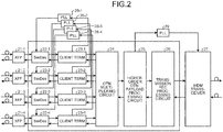
- FIG. 2 is a configuration example of a redundant muxponder according to the present embodiment.
- the redundant muxponder shown in FIG. 2 represents a configuration example having both functions of the transmission-side redundant muxponder 6 and the reception-side redundant muxponder 14.
- the client signal to be input is either one of an STM (Synchronous Transport Module)-64 or 10 GbE. Furthermore, in transmission between the node 101 and the node 102, an optical signal is transmitted as an OTN frame (for example, OUT (Optical Transform Unit) 2 frame).
- STM Serial Transport Module
- OUT Optical Transform Unit
- the interface types of client signals constituting the same client signal can be different from each other or the same.
- the client signal is considered to be either the STM-64 signal or the 10 GbE signal in this example, a client signal of a different interface type can be included.
- the example shown in FIG. 1 represents a case where the input client signals 1-1 and 1-2 are STM-64 signals and the input client signals 1-3 and 1-4 are 10 GbE signals.
- the four-channel client signal is input to XFP modules 21-1 to 21-4 via the transmission-side optical switches 5-1 to 5-4, respectively.
- the XFP (10 Gigabit Small Form Factor Pluggable) modules 21-1 to 21-4 converts the input client signal into serial electrical signals, and respectively outputs the serial electrical signals to SerDes (Serializer/Deserializer) 22-1 to 22-4.
- the SerDes 22-1 to 22-4 convert the input serial electrical signals into parallel electrical signals and respectively outputs the parallel electrical signals to client-signal terminating circuits (Client Term) 23-1 to 23-4.
- the client-signal terminating circuits 23-1 to 23-4 perform signal termination processes according to interface types of the input client signals to generate low-order payload data, outputs the generated low-order payload data to an OTN multiplexing circuit 24, extracts client clocks based on the input client signals by clock extracting circuits according to the interface types, and outputs the extracted client clocks to client PLL circuits (PLL (Phase Lock Loop)) 28-1 to 28-4, respectively.
- PLL circuits PLL circuits
- the client PLL circuits 28-1 to 28-4 perform processes such as jitter suppression on the client clocks extracted by the client-signal terminating circuits 23-1 to 23-4, and outputs the client clocks to the SerDes 22-1 to 22-4, respectively.
- the SerDes 22-1 to 22-4 perform serial-to-parallel conversion processes based on the input client clocks.
- the OTN multiplexing circuit 24 performs a process of multiplexing the input low-order payload data according to the interface type to generate a low order frame accommodating the client signal (low-order payload data), and outputs the generated low order frame to a higher-order OTN-payload processing circuit (HO (Higher Order) OPU (Optical channel Payload Unit) 3/HO ODU (Optical Data Unit) 3 Mapper) 25.
- HO Higher Order
- OPU Optical channel Payload Unit
- 3/HO ODU Optical Data Unit
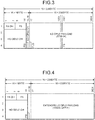
- FIGS. 3 and 4 are an example of a frame configuration of low-order payload data generated by the OTN multiplexing circuit 24.
- FIG. 3 is an example of accommodating a client signal in an LO (Low Order) ODU2 frame compliant with ITU-T (International Telecommunication Union Telecommunication Standardization Sector) G.709 when the client signal is a STM-64 signal
- FIG. 4 is an example of accommodating a client signal in an LO (Low Order) ODU2 frame when the client signal is the 10 GbE signal.
- the configuration of the low-order frame is not limited thereto, and there is no limitation on the configuration of the low-order frame, which can be ODTU23, ODTUG3, or the like.
- the higher-order OTN-payload processing circuit 25 performs a predetermined process including an alarm monitoring process on the input low-order frame to generate higher-order OTN payload data, and outputs the generated higher-order OTN payload data to a transmission FEC (Forward Error Correction) processing circuit 26.
- the higher-order OTN-payload processing circuit 25 further outputs a transmission clock generated in a separate manner to a transmission PLL circuit (PLL) 29.
- a method of generating the transmission clock can be any possible method other than a method extracting a clock from the client signal (that is, as long as it is a method to generate the clock independently of the client signal).
- the transmission FEC processing circuit 26 performs a transmission-side error-correction coding process on the higher-order OTN payload data, and outputs a result of the process to a WDM transceiver (40G WDM Transceiver) 27 as a transmission parallel electrical signal.
- a WDM transceiver 40G WDM Transceiver
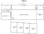
- FIG. 5 is a configuration example of a higher-order frame accommodating low-order frames in a multiplexing manner.
- FIG. 5 shows a configuration example when the higher-order frame is an HO OPU3 frame compliant with ITU-T G.709 of OTU3V-10%.
- the higher-order OTN-payload processing circuit 25 generates a portion except for a portion of the OTU3V-10% FEC (FEC) shown in FIG. 5
- the transmission FEC processing circuit 26 generates the portion of the OTU3V-10% FEC (FEC) shown in FIG. 5 .
- the configuration of the higher-order frame is not limited thereto, and there is no limitation on the configuration of the higher-order frame, which can be HO OPU3 or the like.
- the transmission PLL circuit 29 performs a process such as jitter suppression on the input transmission clock, and inputs a result of the process to the WDM transceiver 27.
- the WDM transceiver 27 performs a parallel-to-serial conversion and an electrical-to-optical conversion on the transmission parallel electrical signal based on the input transmission clock, and outputs a result of the process as a WDM transmission signal light having a predetermined wavelength.
- the four-channel client signals are terminated and multiplexed, output as a WDM transmission signal light, and transmitted to the reception side via the WDM 4.
- the WDM transceiver 27 performs a serial-to-parallel conversion and an optical-to-electrical conversion on an WDM transmission signal light input from the WDM 11, and inputs a result of the process to the transmission FEC processing circuit 26 as a parallel electrical signal.
- the transmission FEC processing circuit 26 performs a reception-side error-correction coding process on the input parallel electrical signal, and outputs a result of the process to the higher-order OTN-payload processing circuit 25.
- the higher-order OTN-payload processing circuit 25 performs a predetermined process including an alarm monitoring process based on the higher-order frame input from the transmission FEC processing circuit 26 as the parallel electrical signal, extracts the higher-order OTN payload data, and outputs the extracted higher-order OTN payload data to the OTN multiplexing circuit 24.
- the OTN multiplexing circuit 24 separates the higher-order OTN payload data into low-order frames, and outputs the separated low-order frames to the respective client-signal terminating circuits 23-1 to 23-4.
- the client-signal terminating circuits 23-1 to 23-4 perform terminating processes on the low-order frames according to a type of the client signal, and outputs results of the processes to the SerDes 22-1 to 22-4, respectively.
- the SerDes 22-1 to 22-4 converts the input parallel electrical signals into serial electrical signals, and outputs the serial electrical signals to the XFPs 21-1 to 21-4, respectively.
- the XFPs 21-1 to 21-4 converts the input serial electrical signals into the client signals, and outputs the client signals.
- the client PLL circuits 28-1 to 28-4 of the respective channels and the transmission PLL circuit 29, which generate the client clocks operate in an independent manner. Therefore, even if the accommodation mode of the client signal (a mode corresponding to an interface type of the client signal accommodated by the redundant muxponder) is changed, the transmission signal clock is not affected by the client clock, and it is possible to switch the accommodation modes of the four client signals at separate timings in an independent manner without having any interference between the client signals.
- configurations of the transmission-side operating muxponders 3-1 to 3-N and the reception-side operating muxponders 12-1 to 12-N are not particularly limited, the same configuration can be taken as the configuration of the redundant muxponder shown in FIG. 2 .
- the transmission-side operating muxponders 3-1 to 3-N and the reception-side operating muxponders 12-1 to 12-N are not necessarily to be provided independently of the client PLL circuits 28-1 to 28-4 and the transmission PLL circuit 29, and it is not necessary to make the interface types of the four client signals respectively settable in an independent manner (for example, all the interface types of the four client signals can be fixed, and the interface types of the four client signals can be changed in a collective manner).
- FIG. 6 is a detailed configuration example of the higher-order frame according to the present embodiment.
- FIG. 7 is an example of a procedure of controlling the accommodation-mode switching according to the present embodiment.
- APS byte for transmitting and receiving information related to accommodation-mode switching between modes at the time of a failure or the like, it is possible to use APS byte in an OH area of an OTN frame. It is possible to use APS (Automatic Protection Switching) byte in an LO ODU2 OH shown in FIG. 3 .
- This APS byte includes bits indicating Request/state, Protection type, Requested Signal, and Bridged Signal.
- switching reason such as an SF (Signal Fail)/request state in the Request/state of the APS byte, a switching type (information on whether it is N:1 switching or 1+1 switching) in the Protection type, a switching request wavelength number in the Requested Signal, and a wavelength number bridged at the transmission side in the Bridged Signal and notifying this method.
- the OH bit of the higher-order frame is used for selecting an accommodation mode of a redundant muxponder that is in standby.
- a six-byte frame alignment signal (FAS) indicating a start position of a frame is stored in an FA (Frame Alignment) OH of the HO ODU3 frame shown in FIG. 6 .
- FA Frame Alignment
- One byte after that is defined as an area for a multi-frame alignment signal (MFAS).
- a counter value that is incremented in a constantly circulating manner as 0x00, 0x01, 0x02, ..., 0xFE, 0xFF, 0x00 for each frame is stored in the multi-frame alignment signal, which is used when configuring a multi-frame by placing a plurality of frames by using this counter value.
- a control of changing the accommodation mode of the redundant muxponder is performed by using a multi-frame APS byte when values from the sixth bit to the eighth bit are all "1" (bill) from among eight bits of an area of the MFAS.
- control of changing the accommodation mode of the redundant muxponder is performed by the multi-frame APS byte when the values from the sixth bit to the eighth bit of the MFAS are all "1"
- FIG. 7 is an example in which a node (Node) A including a transmitting unit and a receiving unit according to the present embodiment and a node (Node) Z including a transmitting unit and a receiving unit according to the present embodiment perform a communication with each other.
- each of the node A and the node Z transmits an NR frame with an NR (No Request) stored in a Request/state portion of an APS byte (Step S1 and Step S2).
- a failure occurs at a wavelength on a transmission path from the node A to the node Z (Step S3), and the receiving unit of the node Z detects the failure (Step S4).
- the detection of the failure can be made using any kind of method, and for example, it is determined that the failure is detected when a frame that is received at regular intervals is not received for a predetermined time.
- the receiving unit of the node Z notifies the transmitting unit of an occurrence of the failure with the wavelength at which the failure is detected, and the transmitting unit transmits an "SF 1, 0" frame in which a wavelength containing wavelength number information for which the failure is detected is stored to the node A.
- the "SF 1, 0" frame indicates that an SF has occurred in the Request/state portion of the APS byte and switching is requested to the counterpart.
- the receiving unit of the node A Upon reception of the "SF 1, 0" frame (Step S5), the receiving unit of the node A performs switching of the transmission-side optical switches 5-1 to 5-4 in such a manner that a client signal bundle corresponding to the wavelength notified by the "SF 1, 0" frame is output to the transmission-side redundant muxponder 6 (Step S6), and performs switching of the accommodation modes of channels (four channels respectively corresponding to the XFPs 21-1 to 21-4) of the transmission-side redundant muxponder 6.
- the transmitting unit of the node A further transmits a "RR 1, 1" frame indicating that switching has been performed due to the failure to the node Z.
- the switching of the transmission-side optical switches 5-1 to 5-4 and the transmission of the "RR 1, 1" frame described above are performed within a time short enough compared to a required time for switching the transmission-side optical switches 5-1 to 5-4 and a required time for switching the accommodation modes (for example, within 10 milliseconds), that is, substantially at the same time.
- the switching of the accommodation modes of the transmission-side redundant muxponder 6 may require a time longer than a time until the "RR 1, 1" frame described above. Furthermore, it may not be possible to generate the low-order frame for a certain time at a channel at which the switching of the accommodation modes of the transmission-side redundant muxponder 6 is performed. Therefore, for example, when an APS control is being performed using the low-order frame, a delay can possibly occur such as the transmission delay of the "RR 1, 1" frame. However, because the APS control is performed using the OH of the higher-order frame in the present embodiment, such a problem does not occur. That is, it is possible to continue the APS control sequence even during performing switching of the accommodation modes of the transmission-side redundant muxponder 6.
- the required time for switching the accommodation modes depends on a mode of each channel in a standby state of the transmission-side redundant muxponder 6 before the switching of the accommodation modes. For example, when two channels from among the four channels have the same accommodation mode in the standby state before the switching and after the switching, it is possible to continue the communication in the same accommodation mode without performing the switching, and reconfiguration (switching) can only be performed on the other two channels.
- the accommodation modes of the transmission-side redundant muxponder 6 and the reception-side redundant muxponder 14 in the standby state are set to the client signal bundle having the high priority, it is possible to continue the communication in the set accommodation mode without performing the switching of the accommodation modes (without any additional interruption of communication due to the switching of the accommodation modes).
- client signals having a high priority in the client signal bundle having the high priority to, for example, a first port, a second port and the like, and set a first port and a second port of the transmission-side redundant muxponder 6 and the reception-side redundant muxponder 14 in the standby state to the accommodation mode of the client signal bundle.
- the agreement of such setting of the ports in the standby state can be performed by using the multi-frame APS byte, by using a control monitoring communication path of a totally separate channel, or can be defined in a fixed manner at the time of establishing a network.
- FIG. 7 is an example in which two channels from among four channels need switching of accommodation modes indicating a required time for switching the accommodation modes with a rectangle that changes its color from white to black.
- Step S7 Upon reception of the "RR 1, 1" frame (Step S7), the node Z performs switching of the accommodation modes of the reception-side redundant muxponder 14. The node Z then performs switching of the transmission-side optical switches 5-1 to 5-4 configured in the same manner in an opposite direction and switching of the accommodation modes of the transmission-side redundant muxponder 6 (Step S8), and transmits the "SF 1, 1" frame indicating that the switching has performed due to the failure to the node A (Step S9). With these processes, switching processes of the transmitting unit and the receiving unit are completed in both directions except for a change of the accommodation modes of the transmission-side redundant muxponder 6 and the reception-side redundant muxponder 14 (change of the interface type of the client signal).
- the node A After a time equal to or longer than a required time for changing the accommodation mode of the transmission-side redundant muxponder 6 or a required time for switching the transmission-side optical switches 5-1 to 5-4, whichever is longer, has elapsed since the "RR 1, 1" frame had been received, the node A performs switching of the reception-side optical switches 13-1 to 13-4.
- the node Z performs switching of the reception-side optical switches 13-1 to 13-4. With this procedure, the whole switching process including switching of the receiving unit and the accommodation modes is completed.
- the node Z is configured to perform the switching of the reception-side optical switches 13-1 to 13-4 after the required time for changing the accommodation mode of the transmission-side redundant muxponder 6 or the required time for switching the transmission-side optical switches 5-1 to 5-4, whichever is longer, has elapsed since the "SF 1, 1" frame had been received, it can be configured that the node Z performs the switching of the reception-side optical switches 13-1 to 13-4 after the required time for changing the accommodation mode of the transmission-side redundant muxponder 6 or the required time for switching the transmission-side optical switches 5-1 to 5-4, whichever is longer, has elapsed since the "SF 1, 0" frame had been received.
- the node Z is configured to perform the switching of the transmission-side optical switches 5-1 to 5-4 and the accommodation modes simultaneously with the reception of the "SF 1, 1" frame or within a shorter time, it can be configured that the node Z performs the switching of the transmission-side optical switches 5-1 to 5-4 and the accommodation modes simultaneously with the reception of the "SF 1, 0" frame.
- the node A and the node Z it can be configured that completion of the switching of the accommodation modes of the transmission-side redundant muxponder 6 and the reception-side redundant muxponder 14 are monitored for each client signal channel and the switching of the transmission-side optical switches 5-1 to 5-4 is performed in an independent manner for each client signal channel based on a result of the monitoring.
- the switching of the transmission-side optical switches 5-1 to 5-4 is performed in an independent manner for each client signal channel based on a required time for switching the accommodation modes of the transmission-side redundant muxponder 6 and the reception-side redundant muxponder 14 for each channel.
- different channels are instructed as switching targets by using the multi-frame APS byte or a multi-frame byte different from the multi-frame APS byte in the "SF 1, 0" frame and in the "SF 1, 1" frame, and the whole switching process is completed with two times of switching operations.
- the accommodation mode of the redundant muxponder can be set independently for each channel of a client signal. Therefore, when accommodating client interfaces in a multiplexing manner by using a muxponder, it is possible to perform redundant switching by one redundant wavelength for a channel that does not need switching of the accommodation modes, for example, only with an instantaneous interruption due to an optical switch of about a few milliseconds, without wasting any additional time for switching the accommodation modes. In addition, it is possible to achieve a reduction of a failure recovery time.
- the present invention has been achieved in view of the above problems, and an object of the present invention is to provide an optical network system and a WDM apparatus that can perform redundant switching by one redundant wavelength when client interfaces are accommodated in a multiplexing manner using a muxponder.
Landscapes
- Engineering & Computer Science (AREA)
- Computer Networks & Wireless Communication (AREA)
- Signal Processing (AREA)
- Optical Communication System (AREA)
- Time-Division Multiplex Systems (AREA)
Claims (15)
- System eines optischen Netzwerks (101, 102), dafür eingerichtet, Übertragungen von N:1-Schutz hinsichtlich Client-Signalen von MxN Kanälen auszuführen, die N Signalbündel mit M Kanälen bilden, wobei M eine Ganzzahl gleich oder größer 2 ist und N eine Ganzzahl gleich oder größer 1 ist, wobei:das Client-Signal mehrere Signalarten beinhaltet unddas System des optischen Netzwerks (101, 102) Folgendes umfasst:eine übertragungsseitige optische redundante Schaltvorrichtung (101), die übertragungsseitig arbeitende Muxponder (3-1 bis 3-N) enthält, die dafür eingerichtet sind, ein gemultiplextes Signal für jedes der Signalbündel zu erzeugen, indem es an den Client-Signalen gemäß einer Art des Client-Signals einen Multiplexing-Prozess ausführt, der einen festgelegten übertragungsseitigen Prozess beinhaltet, und dafür eingerichtet, jedes gemultiplexte Signal in ein optisches Arbeitssignal mit einer anderen Wellenlänge umzuwandeln,einen übertragungsseitigen optischen Koppler (2-1 bis 2-4N), der dafür eingerichtet ist, das Client-Signal in ein Arbeitssignal und ein redundantes Signal für jeden Kanal des Client-Signals zu verzweigen,M parallele übertragungsseitige optische Schalter (5-1 bis 5-4), jeweils dafür eingerichtet, einen Kanal aus den redundanten Signalen der N Signalbündel auszuwählen, und dafür eingerichtet, ein ausgewähltes redundantes Signal als ein redundantes Client-Signal auszugeben, undeinen übertragungsseitigen redundanten Muxponder (6), der dafür eingerichtet ist, ein gemultiplextes Signals zu erzeugen, indem er gemäß einer Art des Signals an den redundanten M-Kanal-Client-Signalen einen Multiplexing-Prozess ausführt, der einen festgelegten übertragungsseitigen Prozess beinhaltet, dafür eingerichtet ist, das gemultiplexte Signal in ein redundantes optisches Signal mit einer anderen Wellenlänge als das optische Arbeitssignal umzuwandeln, und dafür eingerichtet ist, einen Prozess gemäß der Art auszuführen, indem in dem festgelegten übertragungsseitigen Prozess ein Unterbringungsmodus eingestellt wird, der der Art entspricht, wobei der Unterbringungsmodus für jeden Kanal in unabhängiger Weise einstellbar ist, eine erste WDM-Vorrichtung (4), die dafür eingerichtet ist, das optische Arbeitssignal und das redundante optische Signal durch eine Wellenlänge zu multiplexen, und dafür eingerichtet ist, ein wellenlängen-gemultiplextes Signal an einen optischen Übertragungsweg auszugeben, undeine empfangsseitige optische redundante Schaltvorrichtung (102), die Folgendes beinhaltet:eine zweite WDM-Vorrichtung (11), die dafür eingerichtet ist, einen wellenlängengemultiplexten Signaleingang von dem optischen Übertragungsweg zu demultiplexen, und dafür eingerichtet ist, wellenlängen-gedemultiplexte Signale auszugeben,empfangsseitig arbeitende Muxponder (12-1 bis 12-N), die dafür eingerichtet sind, ein Ausgangs-Client-Signal zu erzeugen, indem sie an dem optischen Arbeitssignal aus den wellenlängen-gedemultiplexten Signalen gemäß einer Art des Client-Signals einen Demultiplexing-Prozess ausführen, der einen festgelegten empfangsseitigen Prozess beinhaltet,einen empfangsseitigen redundanten Muxponder (14), der dafür eingerichtet ist, ein Ausgang-Client-Signal zu erzeugen, indem er gemäß einer Art des Client-Signals an dem redundanten Signal aus den wellenlängen-gedemultiplexten Signalen einen Demultiplexing-Prozess ausführt, der einen festgelegten empfangsseitigen Prozess beinhaltet, und dafür eingerichtet ist, einen Prozess gemäß der Art auszuführen, indem in dem festgelegten übertragungsseitigen Prozess ein Unterbringungsmodus eingestellt wird, der der Art entspricht, wobei der Unterbringungsmodus für jeden Kanal in unabhängiger Weise einstellbar ist,einen empfangsseitigen optischen Koppler (15-1 bis 15-4N), der für jeden Kanal der Client-Signale bereitgestellt und dafür eingerichtet ist, ein vom empfangsseitigen redundanten Muxponder erzeugtes Ausgangs-Client-Signal und ein durch den empfangsseitig arbeitenden Muxponder oder die übertragungsseitig arbeitenden Muxponder erzeugten Ausgangs-Client-Signal optisch zu koppeln, undeinen empfangsseitigen optischen Schalter (13-1 bis 13-4), der dafür eingerichtet ist, einen empfangsseitigen optischen Koppler auszuwählen, der einem Kanal entspricht, der durch den übertragungsseitigen optischen Schalter als ein Ausgabeziel für ein Ausgangs-Client-Signal ausgewählt wird, das durch den empfangsseitigen redundanten Muxponder erzeugt wird, und dafür eingerichtet ist, ein vom empfangsseitigen redundanten Muxponder erzeugtes Ausgangs-Client-Signal an einen ausgewählten empfangsseitigen optischen Koppler auszugeben.
- System eines optischen Netzwerks (101, 102) nach Anspruch 1, wobei der übertragungsseitige redundante Muxponder (6) dafür eingerichtet ist, einen Übertragungstakt zu erzeugen, der unabhängig von einem Takt, der aus dem Client-Signal extrahiert wird, verwendet wird, wenn der Multiplexing-Prozess eines Unterbringungsmodus ausgeführt wird.
- System eines optischen Netzwerks (101, 102) nach Anspruch 1 oder 2, wobei die empfangsseitige optische redundante Schaltvorrichtung (102) dafür eingerichtet ist, eine Benachrichtigung über ein Schalten eines Unterbringungsmodus auszuführen, indem ein Overhead-Byte eines Frames höherer Ordnung in einem auf ITU-T G.709 basierenden Mehrfach-Frame verwendet wird.
- System eines optischen Netzwerks nach einem der Ansprüche 1 bis 3, ferner Folgendes umfassend:eine erste redundante Schaltvorrichtung (Knoten A) mit einer Funktion als die übertragungsseitige optische redundante Schaltvorrichtung (101) und einer Funktion als die empfangsseitige optische redundante Schaltvorrichtung (102) undeine zweite redundante Schaltvorrichtung (Knoten Z) mit einer Funktion als die übertragungsseitige optische redundante Schaltvorrichtung (101) und einer Funktion als die empfangsseitige optische redundante Schaltvorrichtung (102), wobei die zweite redundante Schaltvorrichtung der ersten redundanten Schaltvorrichtung gegenüberliegt, wobei:die zweite redundante Schaltvorrichtung dafür eingerichtet ist, nach dem Erkennen (S4) eines Auftretens eines Ausfalls auf einem Weg zwischen der zweiten redundanten Schaltvorrichtung (Knoten Z) und der ersten redundanten Schaltvorrichtung (Knoten A) eine erste Benachrichtigung (SF 1, 0) zu übertragen, die die erste redundante Schaltvorrichtung (Knoten A) über das Auftreten des Ausfalls benachrichtigt, unddie erste redundante Schaltvorrichtung dafür eingerichtet ist, nach dem Empfangen (S5) der ersten Benachrichtigung ein Umschalten der übertragungsseitigen optischen Schalter (5-1 bis 5-4), ein Umschalten von Unterbringungsmodi des übertragungsseitigen redundanten Muxponders (6) und ein Übertragen einer zweiten Benachrichtigung (RR 1,1) an die zweite redundante Schaltvorrichtung (Knoten Z), die eine Reaktion auf die erste Benachrichtigung ist, innerhalb einer Zeitspanne, die kürzer als eine Zeitspanne zum Umwandeln der Unterbringungsmodi und eine Zeitspanne zum Umschalten der übertragungsseitigen optischen Schalter ist, auszuführen.
- System eines optischen Netzwerks nach Anspruch 4, wobei die zweite redundante Schaltvorrichtung (Knoten Z) dafür eingerichtet ist, nach dem Empfang (S7) der zweiten Benachrichtigung (RR 1,1) ein Umschalten der übertragungsseitigen optischen Schalter (5-1 bis 5-4), ein Umschalten von Unterbringungsmodi des übertragungsseitigen redundanten Muxponders (6) und ein Übertragen einer dritten Benachrichtigung (SF 1, 1), welche die erste redundante Schaltvorrichtung (Knoten A) benachrichtigt, dass ein Schalten infolge eines Ausfalls abgeschlossen ist, innerhalb einer Zeitspanne, die kürzer als eine Zeitspanne zum Umwandeln der Unterbringungsmodi und eine Zeitspanne zum Umschalten der übertragungsseitigen optischen Schalter (5-1 bis 5-4) ist, auszuführen.
- System eines optischen Netzwerks nach Anspruch 4 oder 5, wobei die zweite redundante Schaltvorrichtung (Knoten Z) dafür eingerichtet ist, ein Schalten des empfangsseitigen optischen Schalters (13-1 bis 13-4) auszuführen, nachdem eine Bereitschaftszeit, die länger als eine Zeitspanne zum Umwandeln der Unterbringungsmodi und eine Zeitspanne zum Umschalten der übertragungsseitigen optischen Schalter (5-1 bis 5-4) ist, seit dem Empfangen (S7) der zweiten Benachrichtigung (RR 1,1) verstrichen ist.
- System eines optischen Netzwerks nach einem der Ansprüche 4 bis 6, wobei die erste redundante Schaltvorrichtung (Knoten A) dafür eingerichtet ist, ein Umschalten des empfangsseitigen optischen Schalters (13-1 bis 13-4) auszuführen, nachdem eine Bereitschaftszeit, die länger als eine Zeitspanne zum Umwandeln der Unterbringungsmodi und eine Zeitspanne zum Umschalten der übertragungsseitigen optischen Schalter (5-1 bis 5-4) ist, seit dem Empfangen (S5) der ersten Benachrichtigung verstrichen ist.
- System eines optischen Netzwerks nach einem der Ansprüche 1 bis 3, ferner Folgendes umfassend:eine erste redundante Schaltvorrichtung (Knoten A) mit einer Funktion als die übertragungsseitige optische redundante Schaltvorrichtung (101) und einer Funktion als die empfangsseitige optische redundante Schaltvorrichtung (102) undeine zweite redundante Schaltvorrichtung (Knoten Z) mit einer Funktion als die übertragungsseitige optische redundante Schaltvorrichtung (101) und einer Funktion als die empfangsseitige optische redundante Schaltvorrichtung (102), wobei die zweite redundante Schaltvorrichtung (102) der ersten redundanten Schaltvorrichtung (101) gegenüberliegt, wobei:die zweite redundante Schaltvorrichtung dafür eingerichtet ist, nach dem Erkennen (S4) eines Auftretens eines Ausfalls auf einem Weg zwischen der zweiten redundanten Schaltvorrichtung (Knoten Z) und der ersten redundanten Schaltvorrichtung (Knoten A) eine erste Benachrichtigung (SF 1, 0) zu übertragen, die die erste redundante Schaltvorrichtung (Knoten A) über das Auftreten des Ausfalls benachrichtigt, unddie erste redundante Schaltvorrichtung dafür eingerichtet ist, nach dem Empfangen (S5) der ersten Benachrichtigung ein Übertragen einer zweiten Benachrichtigung an die zweite redundante Schaltvorrichtung (Knoten Z) auszuführen, die eine Reaktion auf die erste Benachrichtigung ist.
- System eines optischen Netzwerks nach Anspruch 8, wobei die zweite redundante Schaltvorrichtung (Knoten Z) dafür eingerichtet ist, ein Umschalten des empfangsseitigen optischen Schalters (13-1 bis 13-4) auszuführen, nachdem eine Bereitschaftszeit, die länger als eine Zeitspanne zum Umwandeln der Unterbringungsmodi und eine Zeitspanne zum Umschalten der übertragungsseitigen optischen Schalter (5-1 bis 5-4) ist, seit dem Empfangen (S7) der zweiten Benachrichtigung verstrichen ist.
- System eines optischen Netzwerks nach Anspruch 8 oder 9, wobei die zweite redundante Schaltvorrichtung (Knoten Z) dafür eingerichtet ist, nach dem Empfang (S7) der zweiten Benachrichtigung ein Umschalten (S8) der übertragungsseitigen optischen Schalter (5-1 bis 5-4), ein Umschalten von Unterbringungsmodi des übertragungsseitigen redundanten Muxponders (6) und ein Übertragen (S9) einer dritten Benachrichtigung (SF 1,1), welche die erste redundante Schaltvorrichtung (Knoten A) benachrichtigt, dass ein Schalten infolge eines Ausfalls abgeschlossen ist, innerhalb einer Zeitspanne, die kürzer als eine Zeitspanne zum Umwandeln der Unterbringungsmodi und einer Zeitspanne zum Umschalten der übertragungsseitigen optischen Schalter (5-1 bis 5-4) ist, auszuführen.
- System eines optischen Netzwerks nach Anspruch 10, wobei die erste redundante Schaltvorrichtung (Knoten A) dafür eingerichtet ist, nach dem Empfangen der dritten Benachrichtigung (SF 1, 1) ein Umschalten der übertragungsseitigen optischen Schalter (5-1 bis 5-4) und ein Umschalten von Unterbringungsmodi des übertragungsseitigen redundanten Muxponders (6) innerhalb einer Zeitspanne, die kürzer als eine Zeitspanne zum Umwandeln der Unterbringungsmodi und einer Zeitspanne zum Umschalten der übertragungsseitigen optischen Schalter (5-1 bis 5-4) ist, auszuführen.
- System eines optischen Netzwerks (101, 102) nach Anspruch 10 oder 11, wobei die erste redundante Schaltvorrichtung (Knoten A) dafür eingerichtet ist, ein Umschalten des empfangsseitigen optischen Schalters (13-1 bis 13-4) auszuführen, nachdem eine Bereitschaftszeit, die länger als eine Zeitspanne zum Umwandeln der Unterbringungsmodi und eine Zeitspanne zum Umschalten der übertragungsseitigen optischen Schalter (5-1 bis 5-4) ist, seit dem Empfangen der dritten Benachrichtigung (SF 1,1) verstrichen ist.
- System eines optischen Netzwerks nach einem der Ansprüche 4 bis 12, wobei die erste redundante Schaltvorrichtung (Knoten A) und die zweite redundanten Schaltvorrichtung (Knoten Z) dafür eingerichtet sind, einen Satz Unterbringungsmodi des empfangsseitigen arbeitenden Muxponders (12-1 bis 12-N) entsprechend einem Client-Signalbündel, für das ein Ausfall erkannt wird, mit einem Satz Übertragungsmodi in einer Bereitschaftszeit des übertragungsseitigen redundanten Muxponders (6) und des empfangsseitigen redundanten Muxponders (14) für jeden Client-Signalkanal zu vergleichen und keine Zurücksetzung des Unterbringungsmodus für einen Kanal auszuführen, in dem die Unterbringungsmodi miteinander übereinstimmen.
- System eines optischen Netzwerks nach einem der Ansprüche 4 bis 13, wobei die erste redundante Schaltvorrichtung (Knoten A) und die zweite redundante Schaltvorrichtung (Knoten Z) dafür eingerichtet sind, einen Abschluss des Umschaltens der Unterbringungsmodi in dem übertragungsseitigen redundanten Muxponder (6) und dem empfangsseitigen redundanten Muxponder (14) für jeden Client-Signalkanal zu überwachen und ein Umschalten der übertragungsseitigen optischen Schalter (5-1 bis 5-4) basierend auf einem Ergebnis des Überwachens jedes Client-Signalkanals in einer unabhängigen Weise auszuführen.
- System eines optischen Netzwerks nach einem der Ansprüche 4 bis 13, wobei erste redundante Schaltvorrichtung (Knoten A) und die zweite redundante Schaltvorrichtung (Knoten Z) dafür eingerichtet sind, ein Umschalten der übertragungsseitigen optischen Schalter (5-1 bis 5-4) basierend auf einer für jeden Kanal zum Umschalten der Unterbringungsmodi in dem übertragungsseitigen redundanten Muxponder (6) und dem empfangsseitigen redundanten Muxponder (14) für jeden Client-Signalkanal erforderlichen Zeit in einer unabhängigen Weise auszuführen.
Applications Claiming Priority (1)
| Application Number | Priority Date | Filing Date | Title |
|---|---|---|---|
| JP2011058424A JP5595313B2 (ja) | 2011-03-16 | 2011-03-16 | 光ネットワークシステムおよびwdm装置 |
Publications (3)
| Publication Number | Publication Date |
|---|---|
| EP2501060A2 EP2501060A2 (de) | 2012-09-19 |
| EP2501060A3 EP2501060A3 (de) | 2014-03-05 |
| EP2501060B1 true EP2501060B1 (de) | 2018-05-02 |
Family
ID=45819108
Family Applications (1)
| Application Number | Title | Priority Date | Filing Date |
|---|---|---|---|
| EP12159448.5A Active EP2501060B1 (de) | 2011-03-16 | 2012-03-14 | Optisches Netzwerksystem und WDM-Vorrichtung |
Country Status (4)
| Country | Link |
|---|---|
| US (1) | US8731398B2 (de) |
| EP (1) | EP2501060B1 (de) |
| JP (1) | JP5595313B2 (de) |
| CN (1) | CN102684811A (de) |
Families Citing this family (15)
| Publication number | Priority date | Publication date | Assignee | Title |
|---|---|---|---|---|
| JP5595313B2 (ja) * | 2011-03-16 | 2014-09-24 | 三菱電機株式会社 | 光ネットワークシステムおよびwdm装置 |
| US9288006B1 (en) | 2012-09-21 | 2016-03-15 | Pmc-Sierra Us, Inc. | Demultiplexing high-order to low-order ODU signals in an optical transport network |
| US9564974B2 (en) * | 2013-02-21 | 2017-02-07 | Mitsubishi Electric Corporation | Optical transmission device |
| JP6210729B2 (ja) * | 2013-05-15 | 2017-10-11 | 三菱電機株式会社 | 光伝送システム、送信側光伝送装置及び受信側光伝送装置 |
| US9425893B1 (en) * | 2013-07-31 | 2016-08-23 | Juniper Networks, Inc. | Methods and apparatus for implementing optical integrated routing with traffic protection |
| US9819436B2 (en) | 2013-08-26 | 2017-11-14 | Coriant Operations, Inc. | Intranodal ROADM fiber management apparatuses, systems, and methods |
| US9723385B2 (en) * | 2013-11-06 | 2017-08-01 | Coriant Operations, LLC | Procedures, apparatuses, systems, and computer programs for providing optical network channel protection |
| US20150188625A1 (en) * | 2013-12-27 | 2015-07-02 | Electronics And Telecommunications Research Institute | Method for realizing time reduction in shared mesh network |
| WO2015129290A1 (ja) * | 2014-02-25 | 2015-09-03 | 三菱電機株式会社 | 波長冗長装置及び波長冗長方法 |
| JP6253506B2 (ja) * | 2014-05-15 | 2017-12-27 | 三菱電機株式会社 | 送信装置および光通信システム |
| US10917363B2 (en) * | 2015-06-22 | 2021-02-09 | Infinera Corporation | Multilayer packet optical communication networks |
| US10063336B1 (en) * | 2017-10-24 | 2018-08-28 | Ciena Corporation | Protected transponded services integrated with control plane switched services |
| US10623090B2 (en) * | 2018-05-24 | 2020-04-14 | At&T Intellectual Property I, L.P. | Multi-lane optical transport network recovery |
| CN109274421B (zh) * | 2018-11-20 | 2022-03-01 | 中国电信集团工会上海市委员会 | 一种传输otn网络端到端电路故障自动定位的方法 |
| CN115514442A (zh) * | 2021-06-22 | 2022-12-23 | 中国电信股份有限公司 | 波分链路保护系统和方法 |
Family Cites Families (25)
| Publication number | Priority date | Publication date | Assignee | Title |
|---|---|---|---|---|
| US5216666A (en) * | 1991-12-12 | 1993-06-01 | Alcatel Network Systems, Inc. | 1:n ring-type signal protection apparatus |
| JP2826468B2 (ja) * | 1994-04-27 | 1998-11-18 | 日本電気 株式会社 | 回線切替え装置 |
| JPH08274820A (ja) | 1995-03-31 | 1996-10-18 | Toshiba Corp | 伝送路符号化回路と伝送路復号化回路 |
| US6915075B1 (en) * | 1998-02-24 | 2005-07-05 | Telefonaktiebolaget Lm Ericsson (Publ) | Protection of WDM-channels |
| JP2002505546A (ja) * | 1998-02-24 | 2002-02-19 | テレフオンアクチーボラゲツト エル エム エリクソン(パブル) | 波長分割多重チャネルの保護 |
| US7099578B1 (en) * | 1999-12-16 | 2006-08-29 | Tellabs Operations Inc. | 1:N protection in an optical terminal |
| EP1252792A2 (de) * | 2000-01-31 | 2002-10-30 | PIRELLI SUBMARINE TELECOM SYSTEMS ITALIA S.p.A. | Lineares optisches ünertragungssystem mit fehlerschutz |
| CN1723649A (zh) * | 2001-08-27 | 2006-01-18 | Pts公司 | 核心光网的结构配置 |
| US20030039003A1 (en) * | 2001-08-27 | 2003-02-27 | Bogdan Jakobik | Architectural arrangement for core optical networks |
| US6915036B2 (en) * | 2001-10-25 | 2005-07-05 | Pts Corporation | Field reconfigurable line cards for an optical transport system |
| CN1222821C (zh) * | 2002-07-01 | 2005-10-12 | 华为技术有限公司 | 基于波分复用层的光通道保护装置及方法 |
| US7898944B2 (en) * | 2005-12-14 | 2011-03-01 | Cisco Technology, Inc. | Smart mechanism for multi-client bidirectional optical channel protection scheme |
| JP4984797B2 (ja) * | 2006-09-29 | 2012-07-25 | 富士通株式会社 | 光ネットワークシステム |
| JP4733766B2 (ja) * | 2007-06-08 | 2011-07-27 | 富士通株式会社 | ジッタ制御装置 |
| US8045863B2 (en) * | 2007-12-26 | 2011-10-25 | Ciena Corporation | Byte-interleaving systems and methods for 100G optical transport enabling multi-level optical transmission |
| US8588613B1 (en) * | 2007-12-27 | 2013-11-19 | At&T Intellectual Property I, L.P. | Sync distribution over a non-traffic bearing channel |
| JP5230367B2 (ja) | 2008-06-03 | 2013-07-10 | 日本電信電話株式会社 | パラレル光伝送装置及び方法 |
| JP5132778B2 (ja) | 2008-10-15 | 2013-01-30 | 三菱電機株式会社 | 光ネットワークシステム、光冗長切替え装置およびwdm装置 |
| US8126330B2 (en) * | 2008-12-11 | 2012-02-28 | At&T Intellectual Property I, L.P. | Dynamic wavelength service over a ROADM optical network |
| JP2010147674A (ja) * | 2008-12-17 | 2010-07-01 | Mitsubishi Electric Corp | 波長多重光伝送装置 |
| WO2010100793A1 (ja) * | 2009-03-04 | 2010-09-10 | 三菱電機株式会社 | 光伝送装置 |
| JP5298975B2 (ja) * | 2009-03-10 | 2013-09-25 | 富士通株式会社 | 光伝送システム |
| US8391707B2 (en) * | 2009-11-13 | 2013-03-05 | Verizon Patent And Licensing Inc. | Maintenance friendly optical fiber switching system |
| CN103222213B (zh) * | 2010-11-29 | 2017-02-22 | 三菱电机株式会社 | 波长复用光传输系统、发送装置以及接收装置 |
| JP5595313B2 (ja) * | 2011-03-16 | 2014-09-24 | 三菱電機株式会社 | 光ネットワークシステムおよびwdm装置 |
-
2011
- 2011-03-16 JP JP2011058424A patent/JP5595313B2/ja active Active
-
2012
- 2012-03-14 EP EP12159448.5A patent/EP2501060B1/de active Active
- 2012-03-15 CN CN2012100680129A patent/CN102684811A/zh active Pending
- 2012-03-15 US US13/421,327 patent/US8731398B2/en not_active Expired - Fee Related
Non-Patent Citations (1)
| Title |
|---|
| None * |
Also Published As
| Publication number | Publication date |
|---|---|
| JP5595313B2 (ja) | 2014-09-24 |
| US20120237199A1 (en) | 2012-09-20 |
| CN102684811A (zh) | 2012-09-19 |
| JP2012195782A (ja) | 2012-10-11 |
| EP2501060A3 (de) | 2014-03-05 |
| EP2501060A2 (de) | 2012-09-19 |
| US8731398B2 (en) | 2014-05-20 |
Similar Documents
| Publication | Publication Date | Title |
|---|---|---|
| EP2501060B1 (de) | Optisches Netzwerksystem und WDM-Vorrichtung | |
| JP5132778B2 (ja) | 光ネットワークシステム、光冗長切替え装置およびwdm装置 | |
| CN101453667B (zh) | 数字交叉连接 | |
| US8934479B2 (en) | Super optical channel transport unit signal supported by multiple wavelengths | |
| JP4511557B2 (ja) | 光通信のための方法、装置及びシステム | |
| JP5461229B2 (ja) | クライアント信号収容多重処理装置、クライアント信号クロスコネクト装置、クライアント信号収容多重処理方法 | |
| US10085078B2 (en) | Data processing method, related device, and system for optical transport network | |
| EP3012986B1 (de) | Querverbindungsvorrichtungen für optische kommunikation und signalverarbeitungsverfahren dafür | |
| JP2013038578A (ja) | 光ネットワーク装置 | |
| US9331959B2 (en) | Transmission apparatus and transmission method | |
| JP2007174322A (ja) | 光伝送システムおよび方法 | |
| CA2715359C (en) | Dual asyncronous mapping of client signals of arbitrary rate | |
| JP5736964B2 (ja) | 伝送装置及びデータ伝送方法 | |
| US7313327B2 (en) | Switching control device for wavelength-division multiplexing optical signal | |
| JP2001333440A (ja) | 光ネットワークエレメント | |
| US20150171990A1 (en) | Transmission device, transmission system, and transmission method | |
| EP2112777A2 (de) | Kommunikationsvorrichtung, Kommunikationssystem und Kommunikationsverfahren | |
| Shin et al. | Optical Supervisory Mechanisms in Next-gen OTN for Enhanced Maintenance Functions |
Legal Events
| Date | Code | Title | Description |
|---|---|---|---|
| PUAI | Public reference made under article 153(3) epc to a published international application that has entered the european phase |
Free format text: ORIGINAL CODE: 0009012 |
|
| AK | Designated contracting states |
Kind code of ref document: A2 Designated state(s): AL AT BE BG CH CY CZ DE DK EE ES FI FR GB GR HR HU IE IS IT LI LT LU LV MC MK MT NL NO PL PT RO RS SE SI SK SM TR |
|
| AX | Request for extension of the european patent |
Extension state: BA ME |
|
| PUAL | Search report despatched |
Free format text: ORIGINAL CODE: 0009013 |
|
| AK | Designated contracting states |
Kind code of ref document: A3 Designated state(s): AL AT BE BG CH CY CZ DE DK EE ES FI FR GB GR HR HU IE IS IT LI LT LU LV MC MK MT NL NO PL PT RO RS SE SI SK SM TR |
|
| AX | Request for extension of the european patent |
Extension state: BA ME |
|
| RIC1 | Information provided on ipc code assigned before grant |
Ipc: H04J 3/14 20060101AFI20140124BHEP Ipc: H04J 3/16 20060101ALI20140124BHEP |
|
| 17P | Request for examination filed |
Effective date: 20140728 |
|
| RBV | Designated contracting states (corrected) |
Designated state(s): AL AT BE BG CH CY CZ DE DK EE ES FI FR GB GR HR HU IE IS IT LI LT LU LV MC MK MT NL NO PL PT RO RS SE SI SK SM TR |
|
| STAA | Information on the status of an ep patent application or granted ep patent |
Free format text: STATUS: EXAMINATION IS IN PROGRESS |
|
| 17Q | First examination report despatched |
Effective date: 20161125 |
|
| GRAP | Despatch of communication of intention to grant a patent |
Free format text: ORIGINAL CODE: EPIDOSNIGR1 |
|
| STAA | Information on the status of an ep patent application or granted ep patent |
Free format text: STATUS: GRANT OF PATENT IS INTENDED |
|
| INTG | Intention to grant announced |
Effective date: 20171215 |
|
| GRAS | Grant fee paid |
Free format text: ORIGINAL CODE: EPIDOSNIGR3 |
|
| GRAA | (expected) grant |
Free format text: ORIGINAL CODE: 0009210 |
|
| STAA | Information on the status of an ep patent application or granted ep patent |
Free format text: STATUS: THE PATENT HAS BEEN GRANTED |
|
| AK | Designated contracting states |
Kind code of ref document: B1 Designated state(s): AL AT BE BG CH CY CZ DE DK EE ES FI FR GB GR HR HU IE IS IT LI LT LU LV MC MK MT NL NO PL PT RO RS SE SI SK SM TR |
|
| REG | Reference to a national code |
Ref country code: GB Ref legal event code: FG4D |
|
| REG | Reference to a national code |
Ref country code: CH Ref legal event code: EP Ref country code: AT Ref legal event code: REF Ref document number: 996344 Country of ref document: AT Kind code of ref document: T Effective date: 20180515 |
|
| REG | Reference to a national code |
Ref country code: DE Ref legal event code: R096 Ref document number: 602012045814 Country of ref document: DE Ref country code: IE Ref legal event code: FG4D |
|
| REG | Reference to a national code |
Ref country code: NL Ref legal event code: MP Effective date: 20180502 |
|
| REG | Reference to a national code |
Ref country code: LT Ref legal event code: MG4D |
|
| PG25 | Lapsed in a contracting state [announced via postgrant information from national office to epo] |
Ref country code: ES Free format text: LAPSE BECAUSE OF FAILURE TO SUBMIT A TRANSLATION OF THE DESCRIPTION OR TO PAY THE FEE WITHIN THE PRESCRIBED TIME-LIMIT Effective date: 20180502 Ref country code: SE Free format text: LAPSE BECAUSE OF FAILURE TO SUBMIT A TRANSLATION OF THE DESCRIPTION OR TO PAY THE FEE WITHIN THE PRESCRIBED TIME-LIMIT Effective date: 20180502 Ref country code: FI Free format text: LAPSE BECAUSE OF FAILURE TO SUBMIT A TRANSLATION OF THE DESCRIPTION OR TO PAY THE FEE WITHIN THE PRESCRIBED TIME-LIMIT Effective date: 20180502 Ref country code: NO Free format text: LAPSE BECAUSE OF FAILURE TO SUBMIT A TRANSLATION OF THE DESCRIPTION OR TO PAY THE FEE WITHIN THE PRESCRIBED TIME-LIMIT Effective date: 20180802 Ref country code: BG Free format text: LAPSE BECAUSE OF FAILURE TO SUBMIT A TRANSLATION OF THE DESCRIPTION OR TO PAY THE FEE WITHIN THE PRESCRIBED TIME-LIMIT Effective date: 20180802 Ref country code: LT Free format text: LAPSE BECAUSE OF FAILURE TO SUBMIT A TRANSLATION OF THE DESCRIPTION OR TO PAY THE FEE WITHIN THE PRESCRIBED TIME-LIMIT Effective date: 20180502 |
|
| PG25 | Lapsed in a contracting state [announced via postgrant information from national office to epo] |
Ref country code: GR Free format text: LAPSE BECAUSE OF FAILURE TO SUBMIT A TRANSLATION OF THE DESCRIPTION OR TO PAY THE FEE WITHIN THE PRESCRIBED TIME-LIMIT Effective date: 20180803 Ref country code: NL Free format text: LAPSE BECAUSE OF FAILURE TO SUBMIT A TRANSLATION OF THE DESCRIPTION OR TO PAY THE FEE WITHIN THE PRESCRIBED TIME-LIMIT Effective date: 20180502 Ref country code: LV Free format text: LAPSE BECAUSE OF FAILURE TO SUBMIT A TRANSLATION OF THE DESCRIPTION OR TO PAY THE FEE WITHIN THE PRESCRIBED TIME-LIMIT Effective date: 20180502 Ref country code: HR Free format text: LAPSE BECAUSE OF FAILURE TO SUBMIT A TRANSLATION OF THE DESCRIPTION OR TO PAY THE FEE WITHIN THE PRESCRIBED TIME-LIMIT Effective date: 20180502 Ref country code: RS Free format text: LAPSE BECAUSE OF FAILURE TO SUBMIT A TRANSLATION OF THE DESCRIPTION OR TO PAY THE FEE WITHIN THE PRESCRIBED TIME-LIMIT Effective date: 20180502 |
|
| REG | Reference to a national code |
Ref country code: AT Ref legal event code: MK05 Ref document number: 996344 Country of ref document: AT Kind code of ref document: T Effective date: 20180502 |
|
| PG25 | Lapsed in a contracting state [announced via postgrant information from national office to epo] |
Ref country code: PT Free format text: LAPSE BECAUSE OF FAILURE TO SUBMIT A TRANSLATION OF THE DESCRIPTION OR TO PAY THE FEE WITHIN THE PRESCRIBED TIME-LIMIT Effective date: 20180903 |
|
| PG25 | Lapsed in a contracting state [announced via postgrant information from national office to epo] |
Ref country code: CZ Free format text: LAPSE BECAUSE OF FAILURE TO SUBMIT A TRANSLATION OF THE DESCRIPTION OR TO PAY THE FEE WITHIN THE PRESCRIBED TIME-LIMIT Effective date: 20180502 Ref country code: AT Free format text: LAPSE BECAUSE OF FAILURE TO SUBMIT A TRANSLATION OF THE DESCRIPTION OR TO PAY THE FEE WITHIN THE PRESCRIBED TIME-LIMIT Effective date: 20180502 Ref country code: RO Free format text: LAPSE BECAUSE OF FAILURE TO SUBMIT A TRANSLATION OF THE DESCRIPTION OR TO PAY THE FEE WITHIN THE PRESCRIBED TIME-LIMIT Effective date: 20180502 Ref country code: EE Free format text: LAPSE BECAUSE OF FAILURE TO SUBMIT A TRANSLATION OF THE DESCRIPTION OR TO PAY THE FEE WITHIN THE PRESCRIBED TIME-LIMIT Effective date: 20180502 Ref country code: PL Free format text: LAPSE BECAUSE OF FAILURE TO SUBMIT A TRANSLATION OF THE DESCRIPTION OR TO PAY THE FEE WITHIN THE PRESCRIBED TIME-LIMIT Effective date: 20180502 Ref country code: DK Free format text: LAPSE BECAUSE OF FAILURE TO SUBMIT A TRANSLATION OF THE DESCRIPTION OR TO PAY THE FEE WITHIN THE PRESCRIBED TIME-LIMIT Effective date: 20180502 Ref country code: SK Free format text: LAPSE BECAUSE OF FAILURE TO SUBMIT A TRANSLATION OF THE DESCRIPTION OR TO PAY THE FEE WITHIN THE PRESCRIBED TIME-LIMIT Effective date: 20180502 |
|
| REG | Reference to a national code |
Ref country code: DE Ref legal event code: R097 Ref document number: 602012045814 Country of ref document: DE |
|
| PG25 | Lapsed in a contracting state [announced via postgrant information from national office to epo] |
Ref country code: IT Free format text: LAPSE BECAUSE OF FAILURE TO SUBMIT A TRANSLATION OF THE DESCRIPTION OR TO PAY THE FEE WITHIN THE PRESCRIBED TIME-LIMIT Effective date: 20180502 Ref country code: SM Free format text: LAPSE BECAUSE OF FAILURE TO SUBMIT A TRANSLATION OF THE DESCRIPTION OR TO PAY THE FEE WITHIN THE PRESCRIBED TIME-LIMIT Effective date: 20180502 |
|
| PLBE | No opposition filed within time limit |
Free format text: ORIGINAL CODE: 0009261 |
|
| STAA | Information on the status of an ep patent application or granted ep patent |
Free format text: STATUS: NO OPPOSITION FILED WITHIN TIME LIMIT |
|
| 26N | No opposition filed |
Effective date: 20190205 |
|
| PG25 | Lapsed in a contracting state [announced via postgrant information from national office to epo] |
Ref country code: SI Free format text: LAPSE BECAUSE OF FAILURE TO SUBMIT A TRANSLATION OF THE DESCRIPTION OR TO PAY THE FEE WITHIN THE PRESCRIBED TIME-LIMIT Effective date: 20180502 |
|
| REG | Reference to a national code |
Ref country code: DE Ref legal event code: R119 Ref document number: 602012045814 Country of ref document: DE |
|
| PG25 | Lapsed in a contracting state [announced via postgrant information from national office to epo] |
Ref country code: MC Free format text: LAPSE BECAUSE OF FAILURE TO SUBMIT A TRANSLATION OF THE DESCRIPTION OR TO PAY THE FEE WITHIN THE PRESCRIBED TIME-LIMIT Effective date: 20180502 |
|
| REG | Reference to a national code |
Ref country code: CH Ref legal event code: PL |
|
| GBPC | Gb: european patent ceased through non-payment of renewal fee |
Effective date: 20190314 |
|
| PG25 | Lapsed in a contracting state [announced via postgrant information from national office to epo] |
Ref country code: AL Free format text: LAPSE BECAUSE OF FAILURE TO SUBMIT A TRANSLATION OF THE DESCRIPTION OR TO PAY THE FEE WITHIN THE PRESCRIBED TIME-LIMIT Effective date: 20180502 Ref country code: LU Free format text: LAPSE BECAUSE OF NON-PAYMENT OF DUE FEES Effective date: 20190314 |
|
| REG | Reference to a national code |
Ref country code: BE Ref legal event code: MM Effective date: 20190331 |
|
| PG25 | Lapsed in a contracting state [announced via postgrant information from national office to epo] |
Ref country code: LI Free format text: LAPSE BECAUSE OF NON-PAYMENT OF DUE FEES Effective date: 20190331 Ref country code: CH Free format text: LAPSE BECAUSE OF NON-PAYMENT OF DUE FEES Effective date: 20190331 Ref country code: DE Free format text: LAPSE BECAUSE OF NON-PAYMENT OF DUE FEES Effective date: 20191001 Ref country code: GB Free format text: LAPSE BECAUSE OF NON-PAYMENT OF DUE FEES Effective date: 20190314 Ref country code: IE Free format text: LAPSE BECAUSE OF NON-PAYMENT OF DUE FEES Effective date: 20190314 |
|
| PG25 | Lapsed in a contracting state [announced via postgrant information from national office to epo] |
Ref country code: BE Free format text: LAPSE BECAUSE OF NON-PAYMENT OF DUE FEES Effective date: 20190331 |
|
| PG25 | Lapsed in a contracting state [announced via postgrant information from national office to epo] |
Ref country code: TR Free format text: LAPSE BECAUSE OF FAILURE TO SUBMIT A TRANSLATION OF THE DESCRIPTION OR TO PAY THE FEE WITHIN THE PRESCRIBED TIME-LIMIT Effective date: 20180502 |
|
| PG25 | Lapsed in a contracting state [announced via postgrant information from national office to epo] |
Ref country code: MT Free format text: LAPSE BECAUSE OF NON-PAYMENT OF DUE FEES Effective date: 20190314 |
|
| PG25 | Lapsed in a contracting state [announced via postgrant information from national office to epo] |
Ref country code: CY Free format text: LAPSE BECAUSE OF FAILURE TO SUBMIT A TRANSLATION OF THE DESCRIPTION OR TO PAY THE FEE WITHIN THE PRESCRIBED TIME-LIMIT Effective date: 20180502 |
|
| PG25 | Lapsed in a contracting state [announced via postgrant information from national office to epo] |
Ref country code: IS Free format text: LAPSE BECAUSE OF FAILURE TO SUBMIT A TRANSLATION OF THE DESCRIPTION OR TO PAY THE FEE WITHIN THE PRESCRIBED TIME-LIMIT Effective date: 20180902 |
|
| PG25 | Lapsed in a contracting state [announced via postgrant information from national office to epo] |
Ref country code: HU Free format text: LAPSE BECAUSE OF FAILURE TO SUBMIT A TRANSLATION OF THE DESCRIPTION OR TO PAY THE FEE WITHIN THE PRESCRIBED TIME-LIMIT; INVALID AB INITIO Effective date: 20120314 |
|
| PG25 | Lapsed in a contracting state [announced via postgrant information from national office to epo] |
Ref country code: MK Free format text: LAPSE BECAUSE OF FAILURE TO SUBMIT A TRANSLATION OF THE DESCRIPTION OR TO PAY THE FEE WITHIN THE PRESCRIBED TIME-LIMIT Effective date: 20180502 |
|
| P01 | Opt-out of the competence of the unified patent court (upc) registered |
Effective date: 20230512 |
|
| PGFP | Annual fee paid to national office [announced via postgrant information from national office to epo] |
Ref country code: FR Payment date: 20260209 Year of fee payment: 15 |