EP2501457B1 - Vorrichtung zum rückgewinnen von nanopulver und ultrafeinem pulver aus einem gas - Google Patents
Vorrichtung zum rückgewinnen von nanopulver und ultrafeinem pulver aus einem gas Download PDFInfo
- Publication number
- EP2501457B1 EP2501457B1 EP10777026.5A EP10777026A EP2501457B1 EP 2501457 B1 EP2501457 B1 EP 2501457B1 EP 10777026 A EP10777026 A EP 10777026A EP 2501457 B1 EP2501457 B1 EP 2501457B1
- Authority
- EP
- European Patent Office
- Prior art keywords
- liquid
- vessel
- gas
- sub
- nanometer
- Prior art date
- Legal status (The legal status is an assumption and is not a legal conclusion. Google has not performed a legal analysis and makes no representation as to the accuracy of the status listed.)
- Not-in-force
Links
Images

Classifications
-
- B—PERFORMING OPERATIONS; TRANSPORTING
- B01—PHYSICAL OR CHEMICAL PROCESSES OR APPARATUS IN GENERAL
- B01D—SEPARATION
- B01D47/00—Separating dispersed particles from gases, air or vapours by liquid as separating agent
- B01D47/02—Separating dispersed particles from gases, air or vapours by liquid as separating agent by passing the gas or air or vapour over or through a liquid bath
- B01D47/021—Separating dispersed particles from gases, air or vapours by liquid as separating agent by passing the gas or air or vapour over or through a liquid bath by bubbling the gas through a liquid bath
-
- B—PERFORMING OPERATIONS; TRANSPORTING
- B01—PHYSICAL OR CHEMICAL PROCESSES OR APPARATUS IN GENERAL
- B01D—SEPARATION
- B01D47/00—Separating dispersed particles from gases, air or vapours by liquid as separating agent
- B01D47/06—Spray cleaning
-
- B—PERFORMING OPERATIONS; TRANSPORTING
- B01—PHYSICAL OR CHEMICAL PROCESSES OR APPARATUS IN GENERAL
- B01D—SEPARATION
- B01D47/00—Separating dispersed particles from gases, air or vapours by liquid as separating agent
- B01D47/12—Washers with plural different washing sections
-
- B—PERFORMING OPERATIONS; TRANSPORTING
- B01—PHYSICAL OR CHEMICAL PROCESSES OR APPARATUS IN GENERAL
- B01D—SEPARATION
- B01D47/00—Separating dispersed particles from gases, air or vapours by liquid as separating agent
- B01D47/16—Apparatus having rotary means, other than rotatable nozzles, for atomising the cleaning liquid
-
- B—PERFORMING OPERATIONS; TRANSPORTING
- B82—NANOTECHNOLOGY
- B82Y—SPECIFIC USES OR APPLICATIONS OF NANOSTRUCTURES; MEASUREMENT OR ANALYSIS OF NANOSTRUCTURES; MANUFACTURE OR TREATMENT OF NANOSTRUCTURES
- B82Y15/00—Nanotechnology for interacting, sensing or actuating, e.g. quantum dots as markers in protein assays or molecular motors
-
- B—PERFORMING OPERATIONS; TRANSPORTING
- B82—NANOTECHNOLOGY
- B82Y—SPECIFIC USES OR APPLICATIONS OF NANOSTRUCTURES; MEASUREMENT OR ANALYSIS OF NANOSTRUCTURES; MANUFACTURE OR TREATMENT OF NANOSTRUCTURES
- B82Y40/00—Manufacture or treatment of nanostructures
-
- B—PERFORMING OPERATIONS; TRANSPORTING
- B01—PHYSICAL OR CHEMICAL PROCESSES OR APPARATUS IN GENERAL
- B01D—SEPARATION
- B01D2247/00—Details relating to the separation of dispersed particles from gases, air or vapours by liquid as separating agent
- B01D2247/10—Means for removing the washing fluid dispersed in the gas or vapours
- B01D2247/107—Means for removing the washing fluid dispersed in the gas or vapours using an unstructured demister, e.g. a wire mesh demister
-
- B—PERFORMING OPERATIONS; TRANSPORTING
- B01—PHYSICAL OR CHEMICAL PROCESSES OR APPARATUS IN GENERAL
- B01D—SEPARATION
- B01D2247/00—Details relating to the separation of dispersed particles from gases, air or vapours by liquid as separating agent
- B01D2247/12—Fan arrangements for providing forced draft
-
- B—PERFORMING OPERATIONS; TRANSPORTING
- B01—PHYSICAL OR CHEMICAL PROCESSES OR APPARATUS IN GENERAL
- B01D—SEPARATION
- B01D2247/00—Details relating to the separation of dispersed particles from gases, air or vapours by liquid as separating agent
- B01D2247/14—Fan arrangements for providing induced draft
Definitions
- the invention relates to a device for recovering nanoscale particles ( ⁇ 100 nanometers), also called nanoparticles or nanopowders, and submicron particles (100-500 nanometers), also called ultrafine particles or powders, which would be contained in a gas.
- Nanoparticles Because of their specific properties, nanoparticles have been growing in popularity for several years. Nanoparticles are indeed used as a raw material or as a finished material in various industries, such as aeronautics (as nanocomposites), automobiles (in tires, paint, catalysts). energy (nuclear or photovoltaic energy, petrochemistry), cosmetics (as a structural agent or UV barrier), microelectronics and food processing.
- Particle size is a factor that can strongly influence the toxicity of these particles. Thus certain phases deemed harmless to micrometric scale can become very toxic at the nanoscale.
- nanoparticle production processes on an industrial scale, or simply the development of processes indirectly producing nanoparticles (nanoparticles then being waste that must be contained and recovered), can therefore be dangerous if no precaution is necessary. taken to protect both the people in charge of the production units, the handling and integration of these nanoparticles, but also the environment.
- nanoparticle recovery It is therefore necessary to master the recovery of nanoparticles.
- nanoparticle recovery there are three types of nanoparticle recovery: dry recovery, liquid recovery and wet recovery.
- Dry nanoparticle recovery devices generally operate with processes for manufacturing nanoparticles in a gaseous state (ie processes in which the nanoparticles are produced in a gas stream). They typically include filter barrier collectors that stop the nanoparticles while allowing the process gases to escape. Cyclone devices or electrostatic devices may also be used.
- the collection of nanoparticles is performed when the collectors are full in order to put the nanoparticles in a bag or container.
- Dry collection presents a very high risk of exposure to nanoparticles for personnel with this task. Indeed, during collection, the collectors are open and, because of the high volatility of the nanoparticles (often present in agglomerated form), they are suspended instantly in the air and can therefore be airborne to the air. entrance ways of the human body (nostrils, mouth, ears ).
- One way of ensuring the protection of the personnel concerned is to equip them with full suits and respirators with adequate filtration capacity or functioning by a supply of air from an autonomous circuit.
- Liquid recovery devices consist in putting the nanoparticles, present in a gas, in suspension in a liquid, to then recover this suspension.
- the wet recovery works on the same principle as the liquid recovery, with the difference that instead of recovering a suspension, the suspension is filtered and recovering the still wet particles present on the filter.
- the flow of particles to be suspended is sent to a reservoir containing a liquid.
- the suspension of the particles in the liquid can be obtained by simple bubbling by bringing the flow of particles directly into the liquid using a diffuser, consisting of a sleeve pierced with a multitude of holes. This particular design of the diffuser makes it possible to maximize the exchange surface between the gas stream containing the particles and the liquid.
- the suspension of the particles in the liquid is obtained by vaporizing the liquid in the gas stream.
- the mode of recovery of the nanoparticles in liquid or wet way presents less risks for the personnel and the environment than the mode of recovery in dry way.
- the known devices for recovery in liquid or wet route and in particular the device described in document [1] , are inefficient in the case of mass production of nanoparticles (ie, when the gas flow comprises more than 12.10 4 particles per liter per minute). Indeed, the wettability of the nanoparticles is then not sufficient to allow good capture of all the particles by the liquid. Part of the particles are thus free in the gas and it then becomes necessary to purify the gas (for example using collectors filter barriers ...) so that the nanoparticles that it conveys are not found in fine in the atmosphere. The confinement of these nanoparticles included in the gas leads to a significant additional cost (increased duration of interventions and purchase of filters).
- the inventors have therefore set themselves the goal of improving the liquid or wet recovery of particles of nanometric or submicron size included in a gas flow.
- the droplets have a micrometric size, that is to say a diameter between 1 and 1000 micrometers, or less (submicron).
- the droplets Preferably, have a size of between 0.3 and 10 microns.
- the liquid in which the at least one transducer is immersed will usually be, at the start of the operation of the device, an uncharged liquid which will gradually charge with particles during the operation of the device.
- the electroacoustic transducers of the piezoelectric pellet type used emit ultrasonic waves of high frequencies (from 800 kHz to 3 MHz) and at high powers (more than 100 W).
- the reservoir is separated into two compartments, the liquid opening into one of the compartments being able to pass into the other compartment through a filter, said filter being designed to prevent the passage of the particles present in the liquid.
- the liquid after passing through the filter serving to supply the injection means of at least one liquid in the liquid ring pump and / or the injection means of at least one liquid in the tank.
- the two compartments are located one above the other.
- said at least one transducer is positioned above the filter, while remaining below the level of the liquid / air interface.
- the transducer is placed at a distance of about 10 cm below the liquid / air interface.
- the volume of the compartment in which the at least one transducer is located and the volume of liquid contained in this compartment are such that the transducer can be placed about 30 cm above the filter, while being at 10 cm. below the liquid / air interface.
- the means for introducing the mixture into the reservoir are positioned so as to open above the liquid contained in the reservoir in which the at least one transducer is immersed.
- the means for introducing the mixture into the reservoir are positioned so as to open into the liquid contained in the reservoir in which the at least one transducer is immersed.
- the mixture introduction means are positioned so as to open into the reservoir transversely relative to the bottom of the compartment in which it is or relative to the filter.
- the mixture introduction means are positioned below said at least one transducer.
- the mixture introduction means are positioned as low as possible in the compartment in which they are located.
- the means for introducing the mixture into the reservoir advantageously comprise a diffuser consisting of a sleeve pierced with a multitude of holes.
- the device further comprises liquid introduction means located in the gas evacuation means, after the filtering means.
- the piezoelectric piezoelectric-type electro-acoustic transducer (s) are one transducer per 400 ml of particulate laden liquid present above the transducer when the liquid height above the transducer (s) is 10 cm.
- This value of a transducer per 400 mL of liquid is to be adapted according to the piezoelectric pellets selected.
- there are Chinese-made pellets (model M165D25 of the Pro-Wave brand) that work best when immersed under a liquid height of 45 mm and then produce 400 cc / h of droplets.
- Singceramics Brand, AW16Y20120F2 or AW16Y20120F2 (1.6MHz and 2.4MHz) may also be used.
- the recovery device allows the direct recovery in liquid or wet way of large quantities of particles of nanometric or submicron size by optimizing the suspension of particles in a liquid.
- the suspension of the particles is optimized by increasing the contact surface between the nanometric or submicron particles and the suspension liquid.
- liquid ring pump also known as liquid ring vacuum pump or liquid ring compressor
- a liquid ring pump comprises a cylindrical body (called stator), in which a finned wheel (rotor) rotates along an axis eccentric rotation relative to the axis of rotation of the stator, and two disks placed on either side of the stator, each comprising an opening (or light) through which the gas can penetrate (suction light) in the stator or escape (discharge light).
- stator cylindrical body
- rotor finned wheel
- the liquid ring pump further comprises a liquid inlet, a gas inlet and an outlet of the liquid and gas mixture.
- the liquid is pressed against the periphery of the stator by the centrifugal force received from the impeller and forms a ring concentric with the stator.
- the liquid within the stator thus ensures sealing between the rotor and the stator.
- variable volume capacities are generated between two fins and the liquid ring.
- the liquid ring pump pumps, at controlled pressure, a flow of gas conveying particles out of a particle production chamber (synthesis reactor or effluent treatment unit, for example) and bring it into the stator. Then, the flow of gas carrying the particles comes into contact with the liquid ring, which acts as a liquid wall on which the particles come to impact. So, in the liquid ring pump, the contact between the particles and the liquid is forced by compression / impaction cycles.
- a particle production chamber synthesis reactor or effluent treatment unit, for example
- the nanoparticles are mainly suspended in the liquid, but there may be traces of particles in the gas.
- the optimization of the suspension of the particles is then obtained, in a second step, by passing the particles still present in the gas in a mist of microdroplets.
- the mixture obtained at the outlet of the liquid ring pump comprising the gas and the liquid loaded with nanoparticles, is sent into a reservoir comprising at least one electro-acoustic transducer of the piezoelectric pellet type.
- the pellet (s) are immersed in a liquid and make it possible to generate a dense mist of droplets of micrometric size or smaller in the reservoir.
- the size of the microdroplets is between 0.3 and 10 microns.
- the size of the droplets depends essentially on the frequency of the ultrasound and the physical characteristics (surface tension and density) of the liquid in which the pellets are immersed (see document [2] ).
- the droplet sizes are 0.3 ⁇ m, 1 to 2 ⁇ m, 4 to 5 ⁇ m and 6 to 8 ⁇ m respectively for vibration frequencies of 3 MHz, 2.1 MHz, 1.3 MHz and 800 kHz. .
- the function of the mist of droplets is to trap the last nanoparticles not captured during the passage in the liquid ring pump and present in the gas.
- the capture of the nanoparticles will be all the more effective as the droplets will be fine and the fog dense. Indeed, it is necessary to favor the probability of collision between a drop and a solid nanoparticle. This probability depends essentially on the mobility (speed) of the particles (liquid and gas) and the concentration of particles (density or quantity of drops).
- the mixture comprising the gas and the charged liquid leaving the liquid ring pump opens directly into the liquid present in the reservoir ( Figures 1, 2 , 3 ) (there is bubbling and the gas loaded with traces of particles rises in the fog), or above the liquid, directly in the fog (not shown).
- piezoelectric pellets make it possible to generate a homogeneous and dense fog: the distribution of the size of the droplets is in effect mono dispersed and narrow. In this respect, it is possible to generate 216 cm 3 / h of aerosol with a single pellet, placed in 400 ml of liquid, without having to add a spraying gas, which would have the effect of diluting the aerosol.
- the emission or the amount of fog generated will depend on the ultrasonic power (in our case, it can reach 100 W).
- the fog obtained may cover the entire surface of the liquid, which is particularly important in the case where the mixture comprising the gas and the charged liquid opens into the tank directly into the liquid (bubbling).
- the density of the fog depends on the height of liquid present above the pellets and the power of the ultrasound.
- the liquid height is 10 cm.
- the height of this fog is several centimeters (about 10 cm).
- a density of the order of 18 ml per liter of gas can be reached, which is 14 times greater than that obtained by pneumatic spraying (see document [3] ).
- liquid aerosol mixture microdroplets
- solid aerosol nanoparticles
- This coil has the other function of condensing microdroplets loaded nanoparticles.
- the walls of the coil can optionally be cooled in order to improve the condensation on their surface.
- the coil may for example be metal or ceramic.
- the nanoparticles are produced by a gas phase synthesis process (laser pyrolysis, plasma, evaporation-condensation, combustion, etc.) in a synthesis reactor 1 for example.
- the flow of gas carrying the particles is conducted in a liquid ring pump 2, which is supplied with a liquid, for example water.
- the flow of particles undergoes an impaction phase and a compression phase in the liquid ring pump and is recovered at the outlet of the pump a mixture comprising the gas, the particles and the liquid, the particles being predominantly carried by the liquid.
- This mixture is conducted in a tank 3 comprising a liquid, for example water, and optionally a dispersant, for example 1 ml of dolapix PC21 from Zschimmer and Schwartz, and piezoelectric pellets 7 arranged in the tank so as to be immersed in the liquid.
- a liquid for example water
- a dispersant for example 1 ml of dolapix PC21 from Zschimmer and Schwartz
- piezoelectric pellets 7 arranged in the tank so as to be immersed in the liquid.
- the volume of liquid in the reservoir is calculated so that the pellets are covered by approximately 10 cm of liquid (value calculated by taking as a reference pellets supplied by the company RBI (power of 0 to 100 W and frequency from 800 kHz to 3 MHz)).
- the pellets are excited to form a mist of microdroplets above the liquid in the reservoir.
- the mixture from the liquid ring pump opens into the liquid present in the tank. Bubbling occurs when the gas escapes from the liquid and the gas is in contact with the microdroplets of the fog directly at the liquid outlet.
- the mixture may open above the liquid.
- the gas is discharged from the tank through a system for separating the gas from the charged liquid.
- This separation system here comprises a washing column equipped with a condenser (not shown) and a multistage filtration system 10 comprising at least two types of filters having different porosities chosen so as to separate the gas and the liquid . It is specified that the number of filters used depends on the level of security that one wishes to establish. It is therefore possible to use more than two filters or gas / liquid separators loaded.
- the capacitor allows the condensation of microdroplets loaded with nanoparticles.
- the capacitor may for example be a coil.
- the first filter can be a "mattress desiccator” stainless steel, ceramic or plastic.
- the droplets coalesce in the mattress. Efficiency is going depend on droplet load, thickness and type of mattress.
- the gas After passing through the filtration system, the gas may be washed by placing a washing nozzle 11 at the outlet of the filtration system.
- the gas eventually passes through filters that will prevent any residual nanoparticles from leaving the enclosure with the output gas.
- the filters placed at the end of the column are heated metal absolute filters 12. The heating makes it possible to avoid any condensation of unfilled liquid on the filters. In normal operation, no particles should be deposited on these last filters.
- a heat exchanger 5 may be associated with the filtration system to limit the rise in temperature.
- the device according to the invention may optionally be associated with a pumping system 4 facilitating the suction of gases out of the tank.
- the difference between the three exemplary embodiments is at the reservoir and the liquid supply of the liquid ring pump.
- the tank 3 is equipped with an evacuation located in the bottom of the tank and a viscometer 14 integrated tank.
- the suspension is removed from the tank and is redirected to the liquid ring pump to supply liquid to said pump.
- the suspension that is removed from the tank can also be used to supply something other than the liquid ring pump; for example, in the figure 1 the suspension which is discharged from the tank is also used to feed the washing nozzle 11; a pump 8, for example a peristatic pump, is used to pump the liquid present in the reservoir and to feed the washing nozzle 11.
- a makeup liquid is injected into the circuit through a control valve 15 to maintain the viscosity of the suspension below the threshold value.
- the threshold value will therefore depend on the pellets used and the characteristics of the pump.
- the valve 9 makes it possible to recover the suspension during the experiment.
- suspension evacuation rate and the makeup flow rate are adapted so that there is always liquid in the reservoir when the device is in operation.
- the suspension present in the tank is filtered before being returned to the liquid ring pump to supply liquid or to feed the washing nozzle 11.
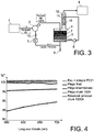
- the tank 3 can thus be equipped with one or more filters 6 for filtering the suspension, as shown in FIGS. figures 2 and 3 . Filtration of the suspension can be done tangentially ( figure 2 ) or frontally ( figure 3 ).
- a filter divides the reservoir 3 into two compartments located one above the other, the piezoelectric pellets being disposed above the filter.
- the device used operates in an unfiltered closed circuit ( figure 1 ).
- the device therefore comprises a liquid ring pump 2, a reservoir 3 equipped with piezoelectric pellets 7, a radio frequency generator for operating the piezoelectric pellets and a capacitor.
- a liquid ring pump 2 a reservoir 3 equipped with piezoelectric pellets 7, a radio frequency generator for operating the piezoelectric pellets and a capacitor.
- the replacement of the two filters by three traps is done in order to better visualize the presence or absence of nanoparticles at these different stages. It is recalled that the number of filters used depends on the level of security that one wishes to establish.
- the flow of nanoparticles is for example produced by a nano powder generator, which is connected to the liquid ring pump.
- the nanoscale powders generator is parameterized so as to produce 75 g of SiC nanoparticles having a diameter of between 35 nm and 37 nm at a rate of 150 g / h of SiC nanoparticles.
- the nanoparticles are carried by a carrier gas, for example argon, and the flow thus produced is injected into the liquid ring pump.
- the entrainment rate of argon is here set at 25 L / min and the particle concentration is for example 0.1 g of particles per liter of argon.
- the liquid that is injected into the pump is for example a solvent composed of 4 liters of water and 1 ml of dispersant, for example Dolapix PC21.
- the addition of the dispersant makes it possible to improve the dispersion of the nanopowders in the suspension.
- the choice of dispersant (s) is made according to the nature of the liquid and the powder forming the suspension.
- the dispersion can also be improved by stirring the suspension with a magnetic bar.
- the tank is a cylindrical chamber 8 cm in diameter and 15 cm high. It comprises, for example, a solvent consisting of 4L of water and 1 mL of dispersant. Under this volume of solvent are placed 10 piezoelectric pellets equidistant from each other. In our exemplary embodiment, the pellets together produce more than 216 cm 3 / h of liquid aerosol.
- the pellets are for example tablets from the company RBI (power from 0 to 100 W and frequency from 800 kHz to 3 MHz). The frequency of the pellets is here 800 kHz, a droplet size of between 6 and 8 micrometers.
- the charged gas and liquid mixture emerging from the liquid ring pump is directed directly into the mist present in the tank.
- the temperature in the tank is 25 ° C and the pressure is 999 mbar.
- the particles in the gas are caught in the droplets of the fog.
- the droplets condense on the capacitor walls and the condensation of the droplets charged with nanopowders is then observed.
- first trap which here consists of a chamber comprising a liquid and in which the gas is bubbled. .
- the trap water is disturbed by the presence of suspended nanopowders, unlike the two traps (which are placed after the first trap) which remain clear.
- the figure 4 presents measurements of UV and Visible transmission of the suspensions or solutions recovered at the reservoir 3 (diluted 1000 times) and of each of the three traps (the solution recovered at the first trap being diluted 100 times before measuring its transmission), the transmission of the water + dolapix PC21 mixture which is introduced into the liquid ring pump is also presented.
- the value of the 100% transmission (+/- 1) shows the absence of particles in the second and third traps (respectively the intermediate trap and the final trap). This result thus demonstrates the effectiveness of the recovery device according to the invention.
- the particular design of the device according to the invention therefore effectively enables us to recover more nanoparticles in the suspension because the wettability of the nanoparticles is improved by increasing the contact surface between the nanoparticles and the liquid. This optimizes the suspension of the particles during their mass production.
- the recovery device according to the invention has many advantages.
- the device according to the invention makes it possible to develop stable suspensions of nanoparticles, which is particularly appreciable since the production of stabilized suspensions is particularly sought after.
- the implementation or the conditioning of the nanopowders pass through a step of suspending the nanoparticles in solvents and very varied formulations.
- the development and stabilization of these suspensions is therefore a key step in the implementation or conditioning of the nanoparticles.
- the quality of the product over time will depend, among other things, on the good dispersion of the active phase (most often TiO 2 titanium oxide nanoparticles).
- the EPI electrophoresis infiltration method mention may be made of the EPI electrophoresis infiltration method.
- nanoparticle suspensions which must have specific properties, particularly in terms of stability, viscosity, mobility and nanopowder concentrations.
- surface treatments of the nanopowders are necessary for their suspension.
- the optimization of nanopowder suspensions is also essential in microelectronics processes derived from printing or "inkjet” technologies such as “roll to roll”, “microcontact printing” or “stamp printing” (printed circuit, photovoltaic cells (“nano-ink”), flat screens ).
- the suspension of nanopowders is a guarantee of safety at work.
- the suspension of nanoparticles can subsequently be sent to a granulation system (atomization-drying or freeze-drying), to a system allowing the functionalization of the nanoparticles (cold plasma for example) or to a device for characterization (granulometry, turbidimeter, viscometer, spectrometer ).
- a granulation system atomization-drying or freeze-drying
- a device for characterization granulometry, turbidimeter, viscometer, spectrometer
Landscapes
- Chemical & Material Sciences (AREA)
- Engineering & Computer Science (AREA)
- Nanotechnology (AREA)
- Chemical Kinetics & Catalysis (AREA)
- Crystallography & Structural Chemistry (AREA)
- Manufacturing & Machinery (AREA)
- General Physics & Mathematics (AREA)
- Condensed Matter Physics & Semiconductors (AREA)
- Physics & Mathematics (AREA)
- Health & Medical Sciences (AREA)
- Life Sciences & Earth Sciences (AREA)
- General Health & Medical Sciences (AREA)
- Molecular Biology (AREA)
- Physical Or Chemical Processes And Apparatus (AREA)
- Separation Of Particles Using Liquids (AREA)
Claims (8)
- Vorrichtung zur Gewinnung von nanometrischen oder submikrometrischen Partikeln, transportiert durch ein Gas, durch Herstellung von stabilisierten Suspensionen von nanometrischen oder submikrometrischen Partikeln, wobei die Vorrichtung einen Behälter (3) umfasst, welcher umfasst:- Injektionsmittel von wenigstens einer Flüssigkeit in den Behälter,- Evakuierungsmittel von Gasen in Höhe des oberen Teils des Behälters nach Filtermitteln (10) für die Partikel,- Auslassmittel (9) für Partikelsuspensionen,dadurch gekennzeichnet, dass die Vorrichtung außerdem eine Flüssigkeitsringpumpe (2) umfasst, bestimmt zum Überführen und zum Verteilen von nanometrischen oder submikrometrischen Partikeln, welche von einem Gas transportiert werden, ganz oder teilweise in einer Flüssigkeit, wobei die Pumpe umfasst:- Einführungsmittel für ein Gas geladen mit nanometrischen oder submikrometrischen Partikeln in die Pumpe,- Injektionsmittel von wenigstens einer Flüssigkeit in die Pumpe, und- Evakuierungsmittel eines Gemisches umfassend die Flüssigkeit geladen mit Partikeln und das Gas erhalten als Ergebnis der Überführung von Partikeln,und dadurch gekennzeichnet, dass der Behälter außerdem umfasst:- Einführungsmittel des Gemischs in den Behälter, und- wenigstens einen elektroakustischen Wandler vom piezoelektrischen Schichttyp (7), vorgesehen, dass er innerhalb des Behälters in eine Flüssigkeit eingetaucht ist, zur Erzeugung eines Tröpfchennebels in mikrometrischer Größe oberhalb der Oberfläche der Flüssigkeit durch Bilden von akustischen Wellen, die sich bis zur Oberfläche der Flüssigkeit ausbreiten.
- Vorrichtung zur Gewinnung von nanometrischen oder submikrometrischen Partikeln gemäß Anspruch 1, in welcher der Behälter (3) in zwei Kompartimente aufgeteilt ist, wobei die in einem der Kompartimente vorhandene Flüssigkeit in das andere Kompartiment übergehen kann, wobei sie durch ein Filter (6) geht, wobei das Filter konzipiert ist, um die Passage von Partikeln, welche in der Flüssigkeit vorhanden sind, zu verhindern, wobei die Flüssigkeit nach ihrer Passage durch das Filter dient, um die Injektionsmittel von wenigstens einer Flüssigkeit in die Flüssigkeitsringpumpe und/oder die Injektionsmittel von wenigstens einer Flüssigkeit in den Behälter zu versorgen.
- Vorrichtung zur Gewinnung von nanometrischen oder submikrometrischen Partikeln gemäß Anspruch 2, in welcher die beiden Kompartimente eines über dem anderen angeordnet sind.
- Vorrichtung zur Gewinnung von nanometrischen oder submikrometrischen Partikeln gemäß Anspruch 2, in welcher der wenigstens eine Wandler (7) über dem Filter (6) angeordnet ist.
- Vorrichtung zur Gewinnung von nanometrischen oder submikrometrischen Partikeln gemäß Anspruch 1, in welcher die Einführungsmittel des Gemischs in den Behälter (3) so angeordnet sind, dass sie oberhalb der in dem Behälter enthaltenen Flüssigkeit, in welcher der wenigstens eine Wandler (7) eingetaucht ist, münden.
- Vorrichtung zur Gewinnung von nanometrischen oder submikrometrischen Partikeln gemäß Anspruch 1, in welcher die Einführungsmittel des Gemischs in den Behälter so angeordnet sind, dass sie in der in dem Behälter enthaltenen Flüssigkeit, in welcher der wenigstens eine Wandler (7) eingetaucht ist, münden.
- Vorrichtung zur Gewinnung von nanometrischen oder submikrometrischen Partikeln gemäß Anspruch 6, in welcher die Einführungsmittel des Gemischs in den Behälter (3) einen Diffusor umfassen, gebildet aus einer gelochten Hülse mit einer Vielzahl von Löchern.
- Vorrichtung zur Gewinnung von nanometrischen oder submikrometrischen Partikeln gemäß Anspruch 1, umfassend außerdem Einführungsmittel einer Flüssigkeit, angeordnet in den Evakuierungsmitteln von Gasen nach den Filtermitteln.
Applications Claiming Priority (2)
| Application Number | Priority Date | Filing Date | Title |
|---|---|---|---|
| FR0958185A FR2952552B1 (fr) | 2009-11-19 | 2009-11-19 | Dispositif de recuperation de nanopoudres et de poudres ultrafines contenues dans un gaz |
| PCT/EP2010/067681 WO2011061224A1 (fr) | 2009-11-19 | 2010-11-17 | Dispositif de recuperation de nanopoudres et de poudres ultrafines contenues dans un gaz |
Publications (2)
| Publication Number | Publication Date |
|---|---|
| EP2501457A1 EP2501457A1 (de) | 2012-09-26 |
| EP2501457B1 true EP2501457B1 (de) | 2017-09-27 |
Family
ID=42332339
Family Applications (1)
| Application Number | Title | Priority Date | Filing Date |
|---|---|---|---|
| EP10777026.5A Not-in-force EP2501457B1 (de) | 2009-11-19 | 2010-11-17 | Vorrichtung zum rückgewinnen von nanopulver und ultrafeinem pulver aus einem gas |
Country Status (8)
| Country | Link |
|---|---|
| US (1) | US8690995B2 (de) |
| EP (1) | EP2501457B1 (de) |
| JP (1) | JP5934650B2 (de) |
| KR (1) | KR101799928B1 (de) |
| CN (1) | CN102686295A (de) |
| ES (1) | ES2654566T3 (de) |
| FR (1) | FR2952552B1 (de) |
| WO (1) | WO2011061224A1 (de) |
Families Citing this family (10)
| Publication number | Priority date | Publication date | Assignee | Title |
|---|---|---|---|---|
| CA3175724C (en) * | 2014-03-20 | 2024-01-09 | Capella Therapeutics, Inc. | Benzimidazole derivatives, and pharmaceutical compositions and methods of use thereof |
| DE102015111330A1 (de) * | 2014-12-17 | 2016-06-23 | Hochschule Osnabrück | Vorrichtung zur Herstellung und/oder Aufreinigung Nanopartikel-gekoppelter Biomaterialien und Verfahren unter Verwendung derselben |
| CN104591305B (zh) * | 2014-12-29 | 2016-01-20 | 河南大学 | 一种纳米线的纯化装置及纯化方法 |
| FR3039433B1 (fr) * | 2015-07-28 | 2017-08-18 | Commissariat Energie Atomique | Methode d'epuration selective d'aerosols |
| JP6542693B2 (ja) * | 2016-02-24 | 2019-07-10 | パナソニック株式会社 | 溶媒分離方法、溶媒分離装置及び溶媒分離システム |
| US11202983B2 (en) * | 2017-11-08 | 2021-12-21 | Btu International, Inc. | Devices, systems and methods for flux removal from furnace process gas |
| WO2019099905A1 (en) * | 2017-11-17 | 2019-05-23 | Saint-Gobain Ceramics & Plastics, Inc. | Filtration process and assembly |
| CN108479255A (zh) * | 2018-03-23 | 2018-09-04 | 登封特卡电子科技有限公司 | 一种太阳能除尘环保设备 |
| CN109530083B (zh) * | 2018-11-28 | 2023-12-12 | 昆明理工大学 | 一种细粒连续干式磁选装置及使用方法 |
| CN113521947B (zh) * | 2021-07-22 | 2022-03-25 | 浙江海河环境科技有限公司 | 一种喷涂漆料回收碳减排技术及装置 |
Family Cites Families (27)
| Publication number | Priority date | Publication date | Assignee | Title |
|---|---|---|---|---|
| JPS51120477A (en) * | 1975-04-14 | 1976-10-21 | Kochiwa Seisakusho:Kk | Ultrasonic dust collector |
| US4181509A (en) * | 1975-06-19 | 1980-01-01 | Envirotech Corporation | Flow preconditioner for electrostatic precipitator |
| JPS5274961A (en) * | 1975-12-18 | 1977-06-23 | Hitachi Plant Eng & Constr Co Ltd | High voltage electrostatic spray type cyclone scrubber |
| JPS57171414A (en) * | 1981-04-14 | 1982-10-22 | Matsushita Electric Ind Co Ltd | Gas scrubbing apparatus |
| US4533368A (en) * | 1982-09-30 | 1985-08-06 | Black & Decker, Inc. | Apparatus for removing respirable aerosols from air |
| US4654054A (en) * | 1982-09-30 | 1987-03-31 | Black & Decker, Inc. | Apparatus for removing respirable aerosols from air |
| JPS6259125U (de) * | 1985-10-01 | 1987-04-13 | ||
| DE3644486A1 (de) * | 1986-12-24 | 1988-07-07 | Kolbus Gmbh & Co Kg | Vorrichtung zum entkeimen von lebensmittelbehaeltern |
| JPH0437618Y2 (de) * | 1987-11-19 | 1992-09-03 | ||
| JPH03288518A (ja) * | 1990-04-02 | 1991-12-18 | Honda Electron Co Ltd | 超音波による空気の清浄方法 |
| JPH0411915A (ja) * | 1990-04-27 | 1992-01-16 | Matsushita Refrig Co Ltd | 空気清浄機 |
| DK0703005T3 (da) * | 1994-09-21 | 2000-05-08 | Allrad No 28 Pty Ltd | En elektrostatisk udfælder |
| US5922103A (en) * | 1995-10-12 | 1999-07-13 | Envirocare International Inc. | Automatic gas conditioning method |
| JP3367038B2 (ja) * | 1997-04-21 | 2003-01-14 | 株式会社 本家松浦酒造場 | アルコール溶液のアルコール分離装置 |
| HK1043690A1 (zh) * | 1999-03-12 | 2002-09-20 | Microscent, Llc. | 用於局部传输有气味浮质的方法和装置 |
| JP2003135922A (ja) * | 2001-11-01 | 2003-05-13 | To Cho | 空気洗浄装置 |
| JP4008719B2 (ja) * | 2002-02-14 | 2007-11-14 | 株式会社加藤製作所 | 吸引車 |
| EP1569293A1 (de) * | 2004-02-25 | 2005-08-31 | Siemens Aktiengesellschaft | Verfahren zum Betrieb einer Brennstoffzellenanlage und Brennstoffzellenanlage |
| DE102004049850A1 (de) * | 2004-09-15 | 2006-03-02 | Cognis Ip Management Gmbh | Verfahren und Anlage zur Herstellung von Mikropartikeln oder Nanopartikeln, Verwendung der Nanopartikel und damit hergestellte Suspension oder Emulsion |
| JP2006096509A (ja) * | 2004-09-29 | 2006-04-13 | Kato Works Co Ltd | 吸引回収装置 |
| JP4922596B2 (ja) * | 2004-10-13 | 2012-04-25 | 福助工業株式会社 | 空調用霧発生装置 |
| US20100011960A1 (en) * | 2005-07-18 | 2010-01-21 | Colin Lawrence | Electrostatic Air Filter |
| EP1963001A1 (de) | 2005-12-13 | 2008-09-03 | Commissariat à l'Energie Atomique | Vorrichtung und verfahren zur herstellung von suspensionen von nanometrischen und submikrometrischen teilchen |
| EP1829614A1 (de) * | 2006-03-02 | 2007-09-05 | Technische Universiteit Delft | Verfahren zur Entfernung von Rußflocken, Feinstaub und Brennkraftmaschinen-Abgaspartikel, Teilchensammelvorrichtung zur Verwendung in diesem Verfahren und Verwendung der Teilchensammelvorrichtung zur Erzeugung eines statischen elektrischen Felds |
| NL2000064C2 (nl) * | 2006-04-28 | 2007-10-30 | Infection Control B V | Werkwijze en inrichting voor het desinfecteren van een ruimte. |
| US8192523B1 (en) * | 2008-02-22 | 2012-06-05 | Tsi Incorporated | Device and method for separating and increasing the concentration of charged particles in a sampled aerosol |
| US8197579B2 (en) * | 2009-06-19 | 2012-06-12 | Empire Technology Development Llc | Gas storage and release using piezoelectric materials |
-
2009
- 2009-11-19 FR FR0958185A patent/FR2952552B1/fr active Active
-
2010
- 2010-11-17 EP EP10777026.5A patent/EP2501457B1/de not_active Not-in-force
- 2010-11-17 US US13/509,310 patent/US8690995B2/en not_active Expired - Fee Related
- 2010-11-17 KR KR1020127014961A patent/KR101799928B1/ko active Active
- 2010-11-17 WO PCT/EP2010/067681 patent/WO2011061224A1/fr not_active Ceased
- 2010-11-17 ES ES10777026.5T patent/ES2654566T3/es active Active
- 2010-11-17 JP JP2012539317A patent/JP5934650B2/ja not_active Expired - Fee Related
- 2010-11-17 CN CN2010800521352A patent/CN102686295A/zh active Pending
Non-Patent Citations (1)
| Title |
|---|
| None * |
Also Published As
| Publication number | Publication date |
|---|---|
| CN102686295A (zh) | 2012-09-19 |
| US20120222558A1 (en) | 2012-09-06 |
| KR101799928B1 (ko) | 2017-11-21 |
| US8690995B2 (en) | 2014-04-08 |
| JP2013511378A (ja) | 2013-04-04 |
| EP2501457A1 (de) | 2012-09-26 |
| FR2952552B1 (fr) | 2012-01-13 |
| WO2011061224A1 (fr) | 2011-05-26 |
| FR2952552A1 (fr) | 2011-05-20 |
| ES2654566T3 (es) | 2018-02-14 |
| KR20120101444A (ko) | 2012-09-13 |
| JP5934650B2 (ja) | 2016-06-15 |
Similar Documents
| Publication | Publication Date | Title |
|---|---|---|
| WO2011061224A1 (fr) | Dispositif de recuperation de nanopoudres et de poudres ultrafines contenues dans un gaz | |
| FR2784607A1 (fr) | Filtration de gaz par force centrifuge | |
| JP4885863B2 (ja) | 抽出装置、分離装置及び抽出方法 | |
| US20130081224A1 (en) | Device for purifying a fluid | |
| FR3002866A1 (fr) | Dispositif et procede de desamiantage | |
| TW201226883A (en) | Sensor chip, detection device, and method of manufacturing sensor chip | |
| WO2012076368A1 (fr) | Procede et dispositif de generation de gouttelettes a spectre granulometrique modulable | |
| FR2889082A1 (fr) | Dispositif d'extraction air/eau par collection electrostatique semi-humide et procede utilisant ce dispositif | |
| FR3039435A1 (fr) | Methode et dispositif de collecte de particules d'aerosols, a collecte selective en fonction de la granulometrie des particules | |
| WO1995007132A1 (fr) | Procede et installation d'epuration d'un gaz par lavage avec une colonne venturi | |
| FR3036635A1 (fr) | Procede de traitement des poussieres retirees d'une surface par un outil et equipement permettant la mise en oeuvre dudit procede | |
| EP0558519B1 (de) | Verfahren zur abtrennung von feststoffen aus einer suspension und anlage zur durchführung des verfahrens | |
| JP5855660B2 (ja) | ナノ粉末または超微細粉末の懸濁液または湿性ペーストを生成する装置および方法 | |
| WO2016198654A1 (fr) | Installation, procédé de dénitration thermique, utilisation d'une telle installation et produit obtenu par un tel procédé | |
| EP0241349A1 (de) | Verfahren und Vorrichtung zur Behandlung von Flüssigkeiten, die Teilchen in Suspension enthalten | |
| FR3066093B1 (fr) | Appareil de desinfection par nebulisation | |
| EP1239938B1 (de) | Verfahren und vorrichtung zur entfernung von feinteiligen partikeln durch perkolation im schüttgut | |
| KR101128847B1 (ko) | 입자 포획 장치 | |
| EP4164763B1 (de) | Vorrichtung zur fest-/flüssigextraktion durch radiale ultraschallbestrahlung und zugehöriges extraktionsverfahren | |
| EP1963001A1 (de) | Vorrichtung und verfahren zur herstellung von suspensionen von nanometrischen und submikrometrischen teilchen | |
| KR101722987B1 (ko) | 기체로부터 혼입된 미립자들을 제거하는 방법 | |
| FR2954176A1 (fr) | Procede d'epuration de l'air et dispositif pour la mise en oeuvre de ce procede | |
| FR2950542A1 (fr) | Dispositif et procede de preparation de particules par nebulisation | |
| WO2019179598A1 (fr) | Particules du type coeur-écorce | |
| JPS62294412A (ja) | 微粒子の捕集装置 |
Legal Events
| Date | Code | Title | Description |
|---|---|---|---|
| PUAI | Public reference made under article 153(3) epc to a published international application that has entered the european phase |
Free format text: ORIGINAL CODE: 0009012 |
|
| 17P | Request for examination filed |
Effective date: 20120524 |
|
| AK | Designated contracting states |
Kind code of ref document: A1 Designated state(s): AL AT BE BG CH CY CZ DE DK EE ES FI FR GB GR HR HU IE IS IT LI LT LU LV MC MK MT NL NO PL PT RO RS SE SI SK SM TR |
|
| RIN1 | Information on inventor provided before grant (corrected) |
Inventor name: GUIZARD, BENOIT Inventor name: MASKROT, HICHAM |
|
| DAX | Request for extension of the european patent (deleted) | ||
| REG | Reference to a national code |
Ref country code: DE Ref legal event code: R079 Ref document number: 602010045578 Country of ref document: DE Free format text: PREVIOUS MAIN CLASS: B01D0047020000 Ipc: B01D0047120000 |
|
| GRAP | Despatch of communication of intention to grant a patent |
Free format text: ORIGINAL CODE: EPIDOSNIGR1 |
|
| STAA | Information on the status of an ep patent application or granted ep patent |
Free format text: STATUS: GRANT OF PATENT IS INTENDED |
|
| RIC1 | Information provided on ipc code assigned before grant |
Ipc: B82Y 40/00 20110101ALI20170321BHEP Ipc: B82Y 15/00 20110101ALI20170321BHEP Ipc: B01D 47/12 20060101AFI20170321BHEP Ipc: B01D 47/06 20060101ALI20170321BHEP Ipc: B01D 47/02 20060101ALI20170321BHEP |
|
| INTG | Intention to grant announced |
Effective date: 20170412 |
|
| GRAS | Grant fee paid |
Free format text: ORIGINAL CODE: EPIDOSNIGR3 |
|
| GRAA | (expected) grant |
Free format text: ORIGINAL CODE: 0009210 |
|
| STAA | Information on the status of an ep patent application or granted ep patent |
Free format text: STATUS: THE PATENT HAS BEEN GRANTED |
|
| AK | Designated contracting states |
Kind code of ref document: B1 Designated state(s): AL AT BE BG CH CY CZ DE DK EE ES FI FR GB GR HR HU IE IS IT LI LT LU LV MC MK MT NL NO PL PT RO RS SE SI SK SM TR |
|
| REG | Reference to a national code |
Ref country code: GB Ref legal event code: FG4D Free format text: NOT ENGLISH |
|
| REG | Reference to a national code |
Ref country code: CH Ref legal event code: EP |
|
| REG | Reference to a national code |
Ref country code: AT Ref legal event code: REF Ref document number: 931469 Country of ref document: AT Kind code of ref document: T Effective date: 20171015 |
|
| REG | Reference to a national code |
Ref country code: IE Ref legal event code: FG4D Free format text: LANGUAGE OF EP DOCUMENT: FRENCH |
|
| REG | Reference to a national code |
Ref country code: DE Ref legal event code: R096 Ref document number: 602010045578 Country of ref document: DE |
|
| REG | Reference to a national code |
Ref country code: FR Ref legal event code: PLFP Year of fee payment: 8 |
|
| PG25 | Lapsed in a contracting state [announced via postgrant information from national office to epo] |
Ref country code: SE Free format text: LAPSE BECAUSE OF FAILURE TO SUBMIT A TRANSLATION OF THE DESCRIPTION OR TO PAY THE FEE WITHIN THE PRESCRIBED TIME-LIMIT Effective date: 20170927 Ref country code: HR Free format text: LAPSE BECAUSE OF FAILURE TO SUBMIT A TRANSLATION OF THE DESCRIPTION OR TO PAY THE FEE WITHIN THE PRESCRIBED TIME-LIMIT Effective date: 20170927 Ref country code: NO Free format text: LAPSE BECAUSE OF FAILURE TO SUBMIT A TRANSLATION OF THE DESCRIPTION OR TO PAY THE FEE WITHIN THE PRESCRIBED TIME-LIMIT Effective date: 20171227 Ref country code: LT Free format text: LAPSE BECAUSE OF FAILURE TO SUBMIT A TRANSLATION OF THE DESCRIPTION OR TO PAY THE FEE WITHIN THE PRESCRIBED TIME-LIMIT Effective date: 20170927 Ref country code: FI Free format text: LAPSE BECAUSE OF FAILURE TO SUBMIT A TRANSLATION OF THE DESCRIPTION OR TO PAY THE FEE WITHIN THE PRESCRIBED TIME-LIMIT Effective date: 20170927 |
|
| REG | Reference to a national code |
Ref country code: NL Ref legal event code: MP Effective date: 20170927 |
|
| REG | Reference to a national code |
Ref country code: LT Ref legal event code: MG4D |
|
| REG | Reference to a national code |
Ref country code: ES Ref legal event code: FG2A Ref document number: 2654566 Country of ref document: ES Kind code of ref document: T3 Effective date: 20180214 |
|
| REG | Reference to a national code |
Ref country code: AT Ref legal event code: MK05 Ref document number: 931469 Country of ref document: AT Kind code of ref document: T Effective date: 20170927 |
|
| PG25 | Lapsed in a contracting state [announced via postgrant information from national office to epo] |
Ref country code: LV Free format text: LAPSE BECAUSE OF FAILURE TO SUBMIT A TRANSLATION OF THE DESCRIPTION OR TO PAY THE FEE WITHIN THE PRESCRIBED TIME-LIMIT Effective date: 20170927 Ref country code: BG Free format text: LAPSE BECAUSE OF FAILURE TO SUBMIT A TRANSLATION OF THE DESCRIPTION OR TO PAY THE FEE WITHIN THE PRESCRIBED TIME-LIMIT Effective date: 20171227 Ref country code: RS Free format text: LAPSE BECAUSE OF FAILURE TO SUBMIT A TRANSLATION OF THE DESCRIPTION OR TO PAY THE FEE WITHIN THE PRESCRIBED TIME-LIMIT Effective date: 20170927 Ref country code: GR Free format text: LAPSE BECAUSE OF FAILURE TO SUBMIT A TRANSLATION OF THE DESCRIPTION OR TO PAY THE FEE WITHIN THE PRESCRIBED TIME-LIMIT Effective date: 20171228 |
|
| PG25 | Lapsed in a contracting state [announced via postgrant information from national office to epo] |
Ref country code: NL Free format text: LAPSE BECAUSE OF FAILURE TO SUBMIT A TRANSLATION OF THE DESCRIPTION OR TO PAY THE FEE WITHIN THE PRESCRIBED TIME-LIMIT Effective date: 20170927 |
|
| PG25 | Lapsed in a contracting state [announced via postgrant information from national office to epo] |
Ref country code: RO Free format text: LAPSE BECAUSE OF FAILURE TO SUBMIT A TRANSLATION OF THE DESCRIPTION OR TO PAY THE FEE WITHIN THE PRESCRIBED TIME-LIMIT Effective date: 20170927 Ref country code: CZ Free format text: LAPSE BECAUSE OF FAILURE TO SUBMIT A TRANSLATION OF THE DESCRIPTION OR TO PAY THE FEE WITHIN THE PRESCRIBED TIME-LIMIT Effective date: 20170927 |
|
| PG25 | Lapsed in a contracting state [announced via postgrant information from national office to epo] |
Ref country code: SK Free format text: LAPSE BECAUSE OF FAILURE TO SUBMIT A TRANSLATION OF THE DESCRIPTION OR TO PAY THE FEE WITHIN THE PRESCRIBED TIME-LIMIT Effective date: 20170927 Ref country code: AT Free format text: LAPSE BECAUSE OF FAILURE TO SUBMIT A TRANSLATION OF THE DESCRIPTION OR TO PAY THE FEE WITHIN THE PRESCRIBED TIME-LIMIT Effective date: 20170927 Ref country code: SM Free format text: LAPSE BECAUSE OF FAILURE TO SUBMIT A TRANSLATION OF THE DESCRIPTION OR TO PAY THE FEE WITHIN THE PRESCRIBED TIME-LIMIT Effective date: 20170927 Ref country code: EE Free format text: LAPSE BECAUSE OF FAILURE TO SUBMIT A TRANSLATION OF THE DESCRIPTION OR TO PAY THE FEE WITHIN THE PRESCRIBED TIME-LIMIT Effective date: 20170927 Ref country code: IS Free format text: LAPSE BECAUSE OF FAILURE TO SUBMIT A TRANSLATION OF THE DESCRIPTION OR TO PAY THE FEE WITHIN THE PRESCRIBED TIME-LIMIT Effective date: 20180127 |
|
| REG | Reference to a national code |
Ref country code: DE Ref legal event code: R097 Ref document number: 602010045578 Country of ref document: DE |
|
| PG25 | Lapsed in a contracting state [announced via postgrant information from national office to epo] |
Ref country code: MC Free format text: LAPSE BECAUSE OF FAILURE TO SUBMIT A TRANSLATION OF THE DESCRIPTION OR TO PAY THE FEE WITHIN THE PRESCRIBED TIME-LIMIT Effective date: 20170927 |
|
| PG25 | Lapsed in a contracting state [announced via postgrant information from national office to epo] |
Ref country code: CH Free format text: LAPSE BECAUSE OF NON-PAYMENT OF DUE FEES Effective date: 20171130 Ref country code: LI Free format text: LAPSE BECAUSE OF NON-PAYMENT OF DUE FEES Effective date: 20171130 Ref country code: DK Free format text: LAPSE BECAUSE OF FAILURE TO SUBMIT A TRANSLATION OF THE DESCRIPTION OR TO PAY THE FEE WITHIN THE PRESCRIBED TIME-LIMIT Effective date: 20170927 |
|
| PLBE | No opposition filed within time limit |
Free format text: ORIGINAL CODE: 0009261 |
|
| STAA | Information on the status of an ep patent application or granted ep patent |
Free format text: STATUS: NO OPPOSITION FILED WITHIN TIME LIMIT |
|
| PG25 | Lapsed in a contracting state [announced via postgrant information from national office to epo] |
Ref country code: PL Free format text: LAPSE BECAUSE OF FAILURE TO SUBMIT A TRANSLATION OF THE DESCRIPTION OR TO PAY THE FEE WITHIN THE PRESCRIBED TIME-LIMIT Effective date: 20170927 Ref country code: LU Free format text: LAPSE BECAUSE OF NON-PAYMENT OF DUE FEES Effective date: 20171117 |
|
| REG | Reference to a national code |
Ref country code: BE Ref legal event code: MM Effective date: 20171130 |
|
| 26N | No opposition filed |
Effective date: 20180628 |
|
| REG | Reference to a national code |
Ref country code: IE Ref legal event code: MM4A |
|
| PG25 | Lapsed in a contracting state [announced via postgrant information from national office to epo] |
Ref country code: MT Free format text: LAPSE BECAUSE OF FAILURE TO SUBMIT A TRANSLATION OF THE DESCRIPTION OR TO PAY THE FEE WITHIN THE PRESCRIBED TIME-LIMIT Effective date: 20170927 |
|
| PG25 | Lapsed in a contracting state [announced via postgrant information from national office to epo] |
Ref country code: IE Free format text: LAPSE BECAUSE OF NON-PAYMENT OF DUE FEES Effective date: 20171117 |
|
| PG25 | Lapsed in a contracting state [announced via postgrant information from national office to epo] |
Ref country code: SI Free format text: LAPSE BECAUSE OF FAILURE TO SUBMIT A TRANSLATION OF THE DESCRIPTION OR TO PAY THE FEE WITHIN THE PRESCRIBED TIME-LIMIT Effective date: 20170927 Ref country code: BE Free format text: LAPSE BECAUSE OF NON-PAYMENT OF DUE FEES Effective date: 20171130 |
|
| PG25 | Lapsed in a contracting state [announced via postgrant information from national office to epo] |
Ref country code: HU Free format text: LAPSE BECAUSE OF FAILURE TO SUBMIT A TRANSLATION OF THE DESCRIPTION OR TO PAY THE FEE WITHIN THE PRESCRIBED TIME-LIMIT; INVALID AB INITIO Effective date: 20101117 |
|
| PG25 | Lapsed in a contracting state [announced via postgrant information from national office to epo] |
Ref country code: CY Free format text: LAPSE BECAUSE OF NON-PAYMENT OF DUE FEES Effective date: 20170927 |
|
| PG25 | Lapsed in a contracting state [announced via postgrant information from national office to epo] |
Ref country code: MK Free format text: LAPSE BECAUSE OF FAILURE TO SUBMIT A TRANSLATION OF THE DESCRIPTION OR TO PAY THE FEE WITHIN THE PRESCRIBED TIME-LIMIT Effective date: 20170927 |
|
| PG25 | Lapsed in a contracting state [announced via postgrant information from national office to epo] |
Ref country code: TR Free format text: LAPSE BECAUSE OF FAILURE TO SUBMIT A TRANSLATION OF THE DESCRIPTION OR TO PAY THE FEE WITHIN THE PRESCRIBED TIME-LIMIT Effective date: 20170927 |
|
| PG25 | Lapsed in a contracting state [announced via postgrant information from national office to epo] |
Ref country code: PT Free format text: LAPSE BECAUSE OF FAILURE TO SUBMIT A TRANSLATION OF THE DESCRIPTION OR TO PAY THE FEE WITHIN THE PRESCRIBED TIME-LIMIT Effective date: 20170927 |
|
| PG25 | Lapsed in a contracting state [announced via postgrant information from national office to epo] |
Ref country code: AL Free format text: LAPSE BECAUSE OF FAILURE TO SUBMIT A TRANSLATION OF THE DESCRIPTION OR TO PAY THE FEE WITHIN THE PRESCRIBED TIME-LIMIT Effective date: 20170927 |
|
| PGFP | Annual fee paid to national office [announced via postgrant information from national office to epo] |
Ref country code: GB Payment date: 20231123 Year of fee payment: 14 |
|
| PGFP | Annual fee paid to national office [announced via postgrant information from national office to epo] |
Ref country code: ES Payment date: 20231215 Year of fee payment: 14 |
|
| PGFP | Annual fee paid to national office [announced via postgrant information from national office to epo] |
Ref country code: IT Payment date: 20231130 Year of fee payment: 14 Ref country code: FR Payment date: 20231120 Year of fee payment: 14 Ref country code: DE Payment date: 20231120 Year of fee payment: 14 |
|
| REG | Reference to a national code |
Ref country code: DE Ref legal event code: R119 Ref document number: 602010045578 Country of ref document: DE |
|
| GBPC | Gb: european patent ceased through non-payment of renewal fee |
Effective date: 20241117 |
|
| PG25 | Lapsed in a contracting state [announced via postgrant information from national office to epo] |
Ref country code: DE Free format text: LAPSE BECAUSE OF NON-PAYMENT OF DUE FEES Effective date: 20250603 |
|
| PG25 | Lapsed in a contracting state [announced via postgrant information from national office to epo] |
Ref country code: IT Free format text: LAPSE BECAUSE OF NON-PAYMENT OF DUE FEES Effective date: 20241117 |
|
| PG25 | Lapsed in a contracting state [announced via postgrant information from national office to epo] |
Ref country code: GB Free format text: LAPSE BECAUSE OF NON-PAYMENT OF DUE FEES Effective date: 20241117 |
|
| PG25 | Lapsed in a contracting state [announced via postgrant information from national office to epo] |
Ref country code: FR Free format text: LAPSE BECAUSE OF NON-PAYMENT OF DUE FEES Effective date: 20241130 |
|
| REG | Reference to a national code |
Ref country code: ES Ref legal event code: FD2A Effective date: 20260105 |
|
| PG25 | Lapsed in a contracting state [announced via postgrant information from national office to epo] |
Ref country code: ES Free format text: LAPSE BECAUSE OF NON-PAYMENT OF DUE FEES Effective date: 20241118 |