EP2501642B1 - Handhabungseinrichtung für eine flugzeugtriebwerkeinheit - Google Patents
Handhabungseinrichtung für eine flugzeugtriebwerkeinheit Download PDFInfo
- Publication number
- EP2501642B1 EP2501642B1 EP10778670.9A EP10778670A EP2501642B1 EP 2501642 B1 EP2501642 B1 EP 2501642B1 EP 10778670 A EP10778670 A EP 10778670A EP 2501642 B1 EP2501642 B1 EP 2501642B1
- Authority
- EP
- European Patent Office
- Prior art keywords
- module
- carriage
- tooling
- aircraft engine
- groove
- Prior art date
- Legal status (The legal status is an assumption and is not a legal conclusion. Google has not performed a legal analysis and makes no representation as to the accuracy of the status listed.)
- Active
Links
Images



Classifications
-
- B—PERFORMING OPERATIONS; TRANSPORTING
- B64—AIRCRAFT; AVIATION; COSMONAUTICS
- B64F—GROUND OR AIRCRAFT-CARRIER-DECK INSTALLATIONS SPECIALLY ADAPTED FOR USE IN CONNECTION WITH AIRCRAFT; DESIGNING, MANUFACTURING, ASSEMBLING, CLEANING, MAINTAINING OR REPAIRING AIRCRAFT, NOT OTHERWISE PROVIDED FOR; HANDLING, TRANSPORTING, TESTING OR INSPECTING AIRCRAFT COMPONENTS, NOT OTHERWISE PROVIDED FOR
- B64F5/00—Designing, manufacturing, assembling, cleaning, maintaining or repairing aircraft, not otherwise provided for; Handling, transporting, testing or inspecting aircraft components, not otherwise provided for
- B64F5/50—Handling or transporting aircraft components
-
- B—PERFORMING OPERATIONS; TRANSPORTING
- B66—HOISTING; LIFTING; HAULING
- B66F—HOISTING, LIFTING, HAULING OR PUSHING, NOT OTHERWISE PROVIDED FOR, e.g. DEVICES WHICH APPLY A LIFTING OR PUSHING FORCE DIRECTLY TO THE SURFACE OF A LOAD
- B66F7/00—Lifting frames, e.g. for lifting vehicles; Platform lifts
- B66F7/06—Lifting frames, e.g. for lifting vehicles; Platform lifts with platforms supported by levers for vertical movement
- B66F7/0625—Lifting frames, e.g. for lifting vehicles; Platform lifts with platforms supported by levers for vertical movement with wheels for moving around the floor
-
- B—PERFORMING OPERATIONS; TRANSPORTING
- B66—HOISTING; LIFTING; HAULING
- B66F—HOISTING, LIFTING, HAULING OR PUSHING, NOT OTHERWISE PROVIDED FOR, e.g. DEVICES WHICH APPLY A LIFTING OR PUSHING FORCE DIRECTLY TO THE SURFACE OF A LOAD
- B66F7/00—Lifting frames, e.g. for lifting vehicles; Platform lifts
- B66F7/06—Lifting frames, e.g. for lifting vehicles; Platform lifts with platforms supported by levers for vertical movement
- B66F7/065—Scissor linkages, i.e. X-configuration
-
- B—PERFORMING OPERATIONS; TRANSPORTING
- B66—HOISTING; LIFTING; HAULING
- B66F—HOISTING, LIFTING, HAULING OR PUSHING, NOT OTHERWISE PROVIDED FOR, e.g. DEVICES WHICH APPLY A LIFTING OR PUSHING FORCE DIRECTLY TO THE SURFACE OF A LOAD
- B66F9/00—Devices for lifting or lowering bulky or heavy goods for loading or unloading purposes
- B66F9/06—Devices for lifting or lowering bulky or heavy goods for loading or unloading purposes movable, with their loads, on wheels or the like, e.g. fork-lift trucks
Definitions
- the present invention relates to a handling assembly of an aircraft engine.
- Aircraft engines are first manufactured in separate modules, which are then assembled together.
- the modules manufactured are transported to the assembly site, then removed from their packages and accurately moved to their docking position at the neighboring module.
- the movements are mainly handled by handling, even if we have gear such as hoists to lift the modules and trolleys to move them.
- the invention relates to a handling assembly of an aircraft engine module which avoids the disadvantages mentioned and makes it possible to prepare the mounting of the module to a neighboring module in better working conditions, more quickly and with manual interventions. much reduced and requiring less precaution.
- DE-A-34 27 042 discloses an aircraft engine handling assembly in which a movable carriage is provided with means for fastening the module and means for adjusting the position of the module, without reproducing other features of the invention and in particular without making any fixing by through a tool attached to one end of the module and offering the possibility to switch the module completely.
- Other trolleys or support devices are the subjects of US-A-1481 503 , US-A-1,600,835 , US-A-2009/020934 and US-A-5,863,034 .
- the invention in a general form, relates to a handling assembly of an aircraft engine module, comprising a mobile carriage and a tool placed at one end of the module, the tooling comprising a mounting and fixing devices to the module.
- the carriage comprises an upper armature established on a support frame of the module and pivotable about a horizontal axis, the upper armature and the tooling comprising complementary devices for fixing the module to the carriage in a position where an axis of the module crosses the axis horizontal.
- the motor module is thus fixed to the trolley by means of the tooling, which is advantageously a "strongback" adapted to the invention: it thus avoids depositing the module on the trolley directly or via an "ear", which reduces the risk of damage by shock or excessive contact pressure. And the tilting of the module, necessary to move from the transport configuration to vertical axis of rotation to the configuration of horizontal axis of rotation, is accomplished in a simple way by the truck, without any special effort or precaution to avoid collisions or to adjust the orientation reached by the module.
- An important element of the assembly is relative to the elevation of the frame, in order to adjust the height of the module at the time of assembly. This is achieved by means of a device which can be independent of the carriage and which then comprises a fixed table at the place where the assembly could take place. The carriage is brought over the table, which raises it to the desired height, the module remaining firmly attached to the carriage.
- Assembly can be accomplished by releasing the module from the cart and lifting it with a hoist.
- the handling assembly can then be completed by a lifting arm extending from one end to the other of the module, being for example fixed to the module at one end and to the tooling at the other end, and equipped with hooking means that can lift it to the center of gravity of the module, which is no longer likely to switch.
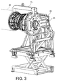
- the aircraft engine module 1 which appears in this embodiment of the invention is called "core" or high pressure body. It is a major intermediate module comprising the compressor and the high pressure turbine, and the combustion chamber. He climbed, according to Figures 1 to 3 , on a carriage 2 comprising a frame 3, rollers 4 mounted on the frame 3 and a frame 5 rising from the frame 3 and carrying the module 1.
- the carriage 2 is, however, raised from the ground and carried by an elevating device 6 comprising a frame 7, and especially arranged in the frame 7, an upper table 8 on which the frame 3 of the carriage 2 is placed, and a mechanism 9 to bar 10 hinged by the middle, disposed between the table 8 and the ground, and which raises that when the hinge angle of the bars 10 is modified by a jack 11.
- a tool 12 taking the appearance of a lid attached to the back of a lid 1 it is originally a "strongback", known in itself and mainly comprising a mount 13 in plate covering the rear of the module 1, to which it is bolted or otherwise fixed by devices not shown, and which allows both to stiffen and protect the module 1, and means, not shown here since already known, carried by the frame 13, to prohibit the translation and rotation movements between the rotor and the stator of the module 1.
- the tool 12 is improved with respect to the known strongbacks: it comprises a protrusion 14 greater than which is fixed a lifting arm 15, the other extr Mite 16 is fixed to the front of the module 1, and which carries in the center a snap ring 18.
- the attachments of the lifting arm are made by inserting a detachable pin 37 through the projection 14 and by a bolting to a flange 17 at the front of module 1.
- complementary attachment means 19 between the tooling 12 and the carriage 2 which comprise a projection 20 standing on the side of the tooling 12, a shoe 21 at the end of the projection 20 and square shape, a groove 22, limited by overhanging edges 23, established in a support 26 at the top of the frame 5, an abutment 24 at the bottom of the groove 22, and a screw 25 between the shoe 21 and the support 26 of the groove 22.
- the support 26 is provided with a pivot 27 of horizontal axis, mounted in the frame 5 and driven by a motor 28, allowing the frame 5 to rotate around this axis.
- the handling handling of module 1 using the device described below is now described.
- the figure 4 shows the module 1 as it appears at the beginning, enclosed in a box 29, with its vertical axis of rotation and the rear of the module 1 directed at the top.
- the first step is to remove a cover 30 of the box 29 and an armature 31 of immobilization of the module 1.
- the module 1 still resting on the bottom 32 of the box 30 but cleared, receives the tooling 12 which is fixed thereto, then the tooling 12 is suspended from a hoist 33 which is hooked to the projection 20 and to a handle 34 (shown in FIG. figure 2 ) projecting from the opposite side of the tooling 12.
- the condition of the figure 5 is obtained.
- the hoist 33 is lifted by driving the tooling 12 and the module 1, a protective cover tooling can then be placed also at the front of the module 1 (the opposite of the tooling 12) and the module 1 is 2.
- Tooling at the front (not shown) is a known "strongback" tool, but it can be lighter and installed by hand, thanks to the handling safety provided by the machine. invention, which subjects module 1 to less effort.
- the installation on the carriage 2 takes place, in the position of the figure 1 , by introducing the shoe 21 into the groove 22, whose orientation is then vertical, leaving down the module 1 until the pad reaches the stop 24, then fixing the screw 25.
- the next step is a rotation of the pivot 27, whose axis crosses that of the module 1, so as to obtain the state represented at the figure 3 by tilting the module 1, its axis then being horizontal and the front of the module 1 protruding from one side of the carriage 2.
- the lifting arm 15 is installed at the top of the assembly, the projection 14 to which it is mounted then being directed upwards.
- the carriage 2 is then moved until it reaches above the table 8 of the elevating device 6, then in a low position and housed in the frame 7; pivotally retractable stops 35 disposed at the front and rear of the frame 3 are then lowered.
- a control of the cylinder 11 produces the rise of the table 8 and the lifting of the carriage 2 and the module 1.
- the hoist 33 can then take the module 1 by the arm to the lift arm 15, lift it from the carriage 2 when the assembly means 19 have been disjointed, then move the module 1 to dock another module 36 of the engine, against which it must be mounted.
- the ring 18 is placed above the center of gravity of the module 1, no tilting is more to be feared.
Landscapes
- Engineering & Computer Science (AREA)
- Structural Engineering (AREA)
- Transportation (AREA)
- Life Sciences & Earth Sciences (AREA)
- Geology (AREA)
- Mechanical Engineering (AREA)
- Civil Engineering (AREA)
- Aviation & Aerospace Engineering (AREA)
- Manufacturing & Machinery (AREA)
- Automatic Assembly (AREA)
- Handcart (AREA)
- Testing Of Engines (AREA)
- Packaging Of Machine Parts And Wound Products (AREA)
Claims (5)
- Anordnung zur Handhabung eines Moduls (1) eines Flugzeugtriebwerks, umfassend einen beweglichen Wagen (2) und ein Gerät (12), das an einem Ende des Moduls (1) angeordnet ist, wobei das Gerät eine Fassung (13) und Vorrichtungen zur Befestigung an dem Modul umfasst, dadurch gekennzeichnet, dass der Wagen ein oberes Gestell (5) umfasst, das auf einem Chassis (3) zum Tragen des Moduls errichtet und um eine horizontale Achse (27) schwenkbar ist, wobei das obere Gestell (5) und das Gerät (12) ergänzende Vorrichtungen zur Befestigung (19) in einer Befestigungsposition des Moduls an dem Wagen, in der eine Rotationsachse des Moduls die horizontale Achse kreuzt, umfassen.
- Anordnung zur Handhabung eines Moduls eines Flugzeugtriebwerks nach Anspruch 1, dadurch gekennzeichnet, dass die ergänzenden Befestigungsvorrichtungen eine Nut (22), die durch hinausragende Ränder (23) begrenzt ist, einen Gleitschuh (21), der in der Nut (22) gleitet und an einem Vorsprung (20) des Gerätes (12), der außerhalb der Nut verläuft, befestigt ist, einen Anschlag (24) des Gleitschuhs in der Nut sowie ein Mittel zum Festlegen (25) des Gleitschuhs in Anschlag in der Nut umfassen.
- Anordnung zur Handhabung eines Moduls eines Flugzeugtriebwerks nach einem der Ansprüche 1 oder 2, dadurch gekennzeichnet, dass sie eine Vorrichtung zum Anheben (6) des Chassis (3) umfasst.
- Anordnung zur Handhabung eines Moduls eines Flugzeugtriebwerks nach Anspruch 3, dadurch gekennzeichnet, dass die Vorrichtung zum Anheben (6) des Chassis einen Tisch (8) umfasst, der von dem Wagen unabhängig ist und auf dem der Wagen fahren kann, wobei zwischen dem Tisch (8) und dem Wagen (2) Festlegungsanschläge (35) vorhanden sind.
- Anordnung zur Handhabung eines Moduls eines Flugzeugtriebwerks nach einem der Ansprüche 1 bis 4, dadurch gekennzeichnet, dass sie einen Hebearm (15) umfasst, der an einem Ende an dem Gerät (12) und an einem gegenüberliegenden Ende (16) an einer Stelle (17) des Moduls, die von dem Gerät abgewandt ist, angebracht werden kann.
Applications Claiming Priority (2)
| Application Number | Priority Date | Filing Date | Title |
|---|---|---|---|
| FR0958240A FR2952922B1 (fr) | 2009-11-20 | 2009-11-20 | Ensemble de manutention d'un module de moteur d'aeronef |
| PCT/EP2010/067858 WO2011061307A1 (fr) | 2009-11-20 | 2010-11-19 | Ensemble de manutention d'un module de moteur d'aeronef |
Publications (2)
| Publication Number | Publication Date |
|---|---|
| EP2501642A1 EP2501642A1 (de) | 2012-09-26 |
| EP2501642B1 true EP2501642B1 (de) | 2013-10-16 |
Family
ID=42238793
Family Applications (1)
| Application Number | Title | Priority Date | Filing Date |
|---|---|---|---|
| EP10778670.9A Active EP2501642B1 (de) | 2009-11-20 | 2010-11-19 | Handhabungseinrichtung für eine flugzeugtriebwerkeinheit |
Country Status (9)
| Country | Link |
|---|---|
| US (1) | US9309008B2 (de) |
| EP (1) | EP2501642B1 (de) |
| JP (1) | JP5701310B2 (de) |
| CN (1) | CN102666360B (de) |
| BR (1) | BR112012011998B1 (de) |
| CA (1) | CA2781226C (de) |
| FR (1) | FR2952922B1 (de) |
| RU (1) | RU2544425C2 (de) |
| WO (1) | WO2011061307A1 (de) |
Families Citing this family (34)
| Publication number | Priority date | Publication date | Assignee | Title |
|---|---|---|---|---|
| FR2969021B1 (fr) | 2010-12-16 | 2014-04-11 | Commissariat Energie Atomique | Dispositif de decoupe de structure comprenant des nano-objets filaires et procede associe |
| US9228451B2 (en) | 2011-05-03 | 2016-01-05 | Pratt & Whitney Canada Corp. | Gas turbine engine module adapter to a carrier |
| FR2980982B1 (fr) | 2011-10-07 | 2014-10-24 | Commissariat Energie Atomique | Dispositif comprenant un materiau composite presentant des nanotubes soumis a un champ electrique et ses utilisations |
| FR2990190B1 (fr) * | 2012-05-02 | 2015-06-19 | Snecma | Outil de manutention d'un module de moteur d'aeronef |
| US9925629B2 (en) * | 2013-05-29 | 2018-03-27 | The Boeing Company | Modular and reconfigurable support system |
| FR3008070B1 (fr) * | 2013-07-08 | 2020-11-06 | Astrium Sas | Bloc propulseur pour vehicule de lancement reutilisable |
| GB2509230A (en) * | 2013-11-19 | 2014-06-25 | Rolls Royce Plc | Gas turbine engine stand with slide rail and lock mechanism |
| CN103639973B (zh) * | 2013-11-28 | 2015-11-18 | 江西洪都航空工业集团有限责任公司 | 一种飞机发动机安装设备 |
| US9738391B2 (en) | 2014-03-10 | 2017-08-22 | United Technologies Corporation | Engine installation system |
| US9505051B2 (en) | 2014-07-09 | 2016-11-29 | The Boeing Company | Mobile platforms for performing operations along an exterior of a fuselage assembly |
| JP6533043B2 (ja) | 2014-08-25 | 2019-06-19 | 三菱航空機株式会社 | 航空機エンジンの取り付け方法 |
| US10196199B2 (en) | 2016-06-01 | 2019-02-05 | General Electric Company | Convertible support structures for shipping large machinery |
| US10279829B2 (en) * | 2016-07-15 | 2019-05-07 | Charles William Walkner | Ergonomic carts for metal forming operations |
| US10131389B1 (en) * | 2017-04-27 | 2018-11-20 | Toyota Motor Engineering & Manufacturing North America, Inc. | Automated guided cart independent securing device |
| CN107089616A (zh) * | 2017-05-05 | 2017-08-25 | 昆明理工大学 | 一种升降平台 |
| CN107671582B (zh) * | 2017-08-29 | 2024-02-06 | 浙江昊能光电股份有限公司 | 一种用于高效切片机上的主轴更换装置 |
| EP3450704B1 (de) | 2017-09-01 | 2020-08-05 | General Electric Company | Turbinenlagerwartungsvorrichtung und -verfahren |
| EP3460272B1 (de) * | 2017-09-20 | 2020-04-01 | Siemens Gamesa Renewable Energy A/S | Verfahren zum wechseln eines lagerbauteils und werkzeugvorrichtung zum wechseln eines lagerbauteils |
| CN107697861B (zh) * | 2017-10-16 | 2019-06-07 | 国网新疆电力公司检修公司 | 变电站智能组件柜空调更换辅助装置 |
| CN108100959B (zh) * | 2017-11-21 | 2019-10-25 | 北京特种机械研究所 | 一种异形圆筒装配平台 |
| CN108502206B (zh) * | 2018-03-16 | 2020-05-08 | 中国航天空气动力技术研究院 | 一种多用途双层无人机机身运输托架 |
| CN109368509B (zh) * | 2018-11-18 | 2020-03-31 | 大连四达高技术发展有限公司 | 飞机发动机智能装配系统 |
| FR3090588B1 (fr) * | 2018-12-21 | 2021-01-22 | Safran Aircraft Engines | Outillage pour placer un ensemble propulsif d’une position horizontale a une position verticale |
| DE102019201797A1 (de) * | 2019-02-12 | 2020-08-13 | MTU Aero Engines AG | Wendestand |
| US11248497B2 (en) * | 2019-04-30 | 2022-02-15 | Pratt & Whitney Canada Corp. | Gas turbine engine yoke and build support |
| CN110640443B (zh) * | 2019-09-03 | 2021-05-04 | 黄鹄科学技术有限公司 | 一种车载设备安装工装 |
| CN112145285B (zh) * | 2020-08-14 | 2021-09-24 | 武汉司南翼航航空工程技术有限责任公司 | 一种低油耗且长航时的航空发动机 |
| US12459669B2 (en) | 2020-08-19 | 2025-11-04 | Safran Aero Boosters | Cart for assembling and transporting an aircraft engine to a test cell |
| CN112977872B (zh) * | 2021-03-29 | 2022-06-10 | 浙江大学 | 一种用于进气道安装的装置及方法 |
| US11247787B1 (en) * | 2021-07-20 | 2022-02-15 | NextGen Aero Support, LLC | Aircraft engine storage frame and system |
| CN120002338B (zh) * | 2023-11-16 | 2025-11-25 | 中国航发商用航空发动机有限责任公司 | 核心机拆解工具及拆解方法 |
| US20260021896A1 (en) * | 2024-07-22 | 2026-01-22 | Pratt & Whitney Canada Corp. | Aircraft engine assembly stand and method of using the same |
| CN119190400B (zh) * | 2024-11-27 | 2025-02-07 | 中航(成都)无人机系统股份有限公司 | 一种大型无人机机翼翻转对接装置及使用方法 |
| CN121223731B (zh) * | 2025-12-02 | 2026-02-24 | 四川航空股份有限公司 | 一种具有清理功能的刹车组件拆卸设备 |
Family Cites Families (34)
| Publication number | Priority date | Publication date | Assignee | Title |
|---|---|---|---|---|
| US1481503A (en) * | 1920-09-24 | 1924-01-22 | Carswell Joseph Sinclair | Repair stand for motors |
| US1600835A (en) * | 1921-10-29 | 1926-09-21 | Robert E Manley | Engine stand |
| US1812585A (en) | 1928-09-21 | 1931-06-30 | Atlas Press Company | Engine stand |
| FR868161A (fr) | 1938-09-19 | 1941-12-23 | Messerschmitt Boelkow Blohm | Chariot pour des dispositifs auxiliaires de forme extérieure et de dimensions différentes, surtout pour la construction d'avions |
| US2712874A (en) * | 1950-05-12 | 1955-07-12 | Lockheed Aircraft Corp | Portable aircraft lifting cradle |
| US2825477A (en) * | 1953-09-04 | 1958-03-04 | Henry M Ross | Engine work stand and method of using the same |
| US2763053A (en) * | 1955-06-09 | 1956-09-18 | Wisconsin Hydraulics Inc | Universal work positioners |
| US3318466A (en) * | 1965-06-16 | 1967-05-09 | Lockheed Aircraft Corp | Tool for removing and replacing component structures of aircraft |
| US3355162A (en) * | 1966-06-07 | 1967-11-28 | Robert M Kerr | Repair stand |
| DE2719850C3 (de) | 1977-05-04 | 1981-06-25 | MTU Motoren- und Turbinen-Union München GmbH, 8000 München | Vorrichtung zur Wartung von Gasturbinentriebwerken, insbesondere Gasturbinenstrahltriebwerken |
| FR2478575A1 (fr) * | 1980-03-19 | 1981-09-25 | Snecma | Dispositif de mise en place d'un reacteur dans une cellule d'avion |
| DE3427042A1 (de) * | 1984-07-21 | 1985-02-21 | Scheele Ing.-Büro GmbH, 2875 Ganderkesee | Universal-flugzeug-triebwerk-wechsel -vorrichtung |
| US4691904A (en) | 1985-08-08 | 1987-09-08 | Robert J. Williams | Automatic or standard transmission handling device |
| US4682750A (en) * | 1986-09-26 | 1987-07-28 | Eidos Corporation | Low profile extensible support platform |
| JPH01237230A (ja) * | 1988-03-18 | 1989-09-21 | Kawasaki Heavy Ind Ltd | エンジン保持・搬送装置 |
| RU2076831C1 (ru) * | 1990-04-23 | 1997-04-10 | Акционерное общество открытого типа "Нижегородский авиастроительный завод "Сокол" | Устройство для транспортировки, подъема и подвески груза на летательный аппарат |
| US5816367A (en) * | 1995-11-30 | 1998-10-06 | Stanley Aviation Corporation | Jet aircraft engine transport apparatus |
| US5863034A (en) * | 1996-10-24 | 1999-01-26 | Vauter; Andrew F. | Work piece stand |
| DE20023688U1 (de) | 2000-06-19 | 2005-08-11 | Berger, Erwin | Vorrichtung zum Handhaben von Werkstücken, insbesondere von Türen |
| US6490906B1 (en) * | 2001-03-02 | 2002-12-10 | Rick H. Bailey | Vehicle body repair tool |
| US6619640B1 (en) * | 2001-08-28 | 2003-09-16 | Gregory Ploski | Support and rotating apparatus for heavy vehicle components mounted on a carriage |
| RU2209155C1 (ru) * | 2001-12-05 | 2003-07-27 | Открытое акционерное общество "Ракетно-космическая корпорация "Энергия" им. С.П.Королева" | Способ сборки головного блока на переходнике ракеты-носителя (варианты) и устройство для осуществления способа (варианты) |
| CN2554091Y (zh) * | 2002-06-28 | 2003-06-04 | 焦宇 | 飞机座椅维修工作台 |
| FR2860175B1 (fr) | 2003-09-26 | 2006-03-10 | Plastic Omnium Cie | Chassis d'un poste de montage de pare-chocs de vehicules automobiles et poste de montage de pare-chocs de vehicules automobiles |
| US7637487B2 (en) * | 2004-06-15 | 2009-12-29 | Thk Co., Ltd. | XY guide table |
| DE202004018795U1 (de) * | 2004-12-03 | 2006-04-13 | Kuka Schweissanlagen Gmbh | Werkstückpositionierer |
| US20090020934A1 (en) * | 2005-09-29 | 2009-01-22 | W.P.R.W.M.D.M., L.L.C. | Equipment handling apparatus and system |
| GB0613929D0 (en) * | 2006-07-13 | 2006-08-23 | Rolls Royce Plc | An engine core stand arrangement and method of removal and transportation of an engine core |
| US7963542B2 (en) * | 2008-08-29 | 2011-06-21 | Solar Turbines Incorporated | Modular cart for a gas turbine engine |
| US8262050B2 (en) * | 2008-12-24 | 2012-09-11 | General Electric Company | Method and apparatus for mounting and dismounting an aircraft engine |
| US8621873B2 (en) * | 2008-12-29 | 2014-01-07 | Solar Turbines Inc. | Mobile platform system for a gas turbine engine |
| FR2948636B1 (fr) * | 2009-07-31 | 2012-01-13 | Airbus Operations Sas | Ensemble moteur pour aeronef dont le mat d'accrochage comprend une enveloppe structurale formant delimitation radiale interne du flux secondaire |
| FR2952921B1 (fr) * | 2009-11-20 | 2012-05-25 | Snecma | Chariot de transport d'un module de moteur d'aeronef |
| FR2969021B1 (fr) | 2010-12-16 | 2014-04-11 | Commissariat Energie Atomique | Dispositif de decoupe de structure comprenant des nano-objets filaires et procede associe |
-
2009
- 2009-11-20 FR FR0958240A patent/FR2952922B1/fr not_active Expired - Fee Related
-
2010
- 2010-11-19 BR BR112012011998-2A patent/BR112012011998B1/pt active IP Right Grant
- 2010-11-19 RU RU2012124417/11A patent/RU2544425C2/ru active
- 2010-11-19 EP EP10778670.9A patent/EP2501642B1/de active Active
- 2010-11-19 CN CN201080052516.0A patent/CN102666360B/zh active Active
- 2010-11-19 JP JP2012539344A patent/JP5701310B2/ja active Active
- 2010-11-19 CA CA2781226A patent/CA2781226C/fr active Active
- 2010-11-19 US US13/509,304 patent/US9309008B2/en active Active
- 2010-11-19 WO PCT/EP2010/067858 patent/WO2011061307A1/fr not_active Ceased
Also Published As
| Publication number | Publication date |
|---|---|
| CN102666360B (zh) | 2015-04-01 |
| CA2781226A1 (fr) | 2011-05-26 |
| US20120224944A1 (en) | 2012-09-06 |
| JP2013511643A (ja) | 2013-04-04 |
| BR112012011998B1 (pt) | 2020-08-11 |
| CA2781226C (fr) | 2017-01-10 |
| RU2544425C2 (ru) | 2015-03-20 |
| FR2952922A1 (fr) | 2011-05-27 |
| BR112012011998A2 (pt) | 2016-05-10 |
| CN102666360A (zh) | 2012-09-12 |
| WO2011061307A1 (fr) | 2011-05-26 |
| JP5701310B2 (ja) | 2015-04-15 |
| US9309008B2 (en) | 2016-04-12 |
| FR2952922B1 (fr) | 2012-05-25 |
| EP2501642A1 (de) | 2012-09-26 |
| RU2012124417A (ru) | 2013-12-27 |
Similar Documents
| Publication | Publication Date | Title |
|---|---|---|
| EP2501642B1 (de) | Handhabungseinrichtung für eine flugzeugtriebwerkeinheit | |
| EP0147246B1 (de) | Transportgestell für Turbomaschine | |
| EP3278930B1 (de) | Vorrichtung zum einsetzen oder herausnehmen einer glasscheibe eines kraftfahrzeugs | |
| EP1773707A1 (de) | Hebeanordnung | |
| FR2487318A1 (fr) | Procede d'extension d'un bras de grue telescopique | |
| FR2990190A1 (fr) | Outil de manutention d'un module de moteur d'aeronef | |
| EP2649004B1 (de) | Werkzeug zur handhabung einer abwasserkanalabdeckung | |
| EP3838666B1 (de) | Halterung zum anheben von behältern an den oberen behälteröffnungen | |
| WO2015185811A1 (fr) | Ensemble de manutention d'un moteur d'aéronef | |
| FR2887396A1 (fr) | Tondeuse a gazon autoportee ayant une unite de tondeuse frontale | |
| FR2822145A1 (fr) | Nacelle elevatrice avec plate-forme et structure de support de charge associee | |
| FR3058704A1 (fr) | Berceau bipartite a coulissement pour turbopropulseur | |
| EP3889094B1 (de) | Kran mit automatisierter montage, der ein abnehmbares ballastelement für den transport auf einem sattel umfasst | |
| EP0330572A1 (de) | Einziehbarer Arm zum Aufnehmen und Absetzen einer Last und Fahrzeug, ausgerüstet damit | |
| FR2867497A1 (fr) | Dispositif d'aide au decoffrage | |
| EP4015313B1 (de) | Vorrichtung zum halten und abnehmen einer ausrüstung in bezug auf eine aussenwand eines fahrzeugs und anwendungsverfahren für eine solche vorrichtung | |
| FR2814038A1 (fr) | Dispositif de relevage pour tracteur permettant d'atteler et de deteler une masse sans intervention manuelle | |
| EP3383787B1 (de) | Wartungsverfahren und system für solarempfänger | |
| EP2829501B1 (de) | Ausleger-Montagevorrichtung eines Mitnahmestaplers, der hinten auf einem Zugfahrzeug, wie einem LKW, befestigt ist | |
| EP4490359B1 (de) | Multifunktionelles stadtfahrzeug mit mitteln zum schnellen werkzeugwechsel | |
| EP2602210B1 (de) | Behälter für Kraftfahrzeugteile | |
| EP2096077B1 (de) | Selbstfahrende Hubarbeitsbühne | |
| EP1630121B1 (de) | Greifrahmen | |
| EP2821280B1 (de) | Herausnehmbarer Behälter für Fahrzeug | |
| FR2524404A1 (fr) | Plate-forme elevatrice, notamment pour vehicule industriel |
Legal Events
| Date | Code | Title | Description |
|---|---|---|---|
| PUAI | Public reference made under article 153(3) epc to a published international application that has entered the european phase |
Free format text: ORIGINAL CODE: 0009012 |
|
| 17P | Request for examination filed |
Effective date: 20120611 |
|
| AK | Designated contracting states |
Kind code of ref document: A1 Designated state(s): AL AT BE BG CH CY CZ DE DK EE ES FI FR GB GR HR HU IE IS IT LI LT LU LV MC MK MT NL NO PL PT RO RS SE SI SK SM TR |
|
| DAX | Request for extension of the european patent (deleted) | ||
| REG | Reference to a national code |
Ref country code: DE Ref legal event code: R079 Ref document number: 602010011039 Country of ref document: DE Free format text: PREVIOUS MAIN CLASS: B66F0009120000 Ipc: B64F0005000000 |
|
| RIC1 | Information provided on ipc code assigned before grant |
Ipc: B66F 7/06 20060101ALI20130314BHEP Ipc: B25H 1/00 20060101ALI20130314BHEP Ipc: B66C 23/48 20060101ALI20130314BHEP Ipc: B64F 5/00 20060101AFI20130314BHEP Ipc: B66F 9/06 20060101ALI20130314BHEP |
|
| GRAP | Despatch of communication of intention to grant a patent |
Free format text: ORIGINAL CODE: EPIDOSNIGR1 |
|
| INTG | Intention to grant announced |
Effective date: 20130531 |
|
| GRAS | Grant fee paid |
Free format text: ORIGINAL CODE: EPIDOSNIGR3 |
|
| GRAA | (expected) grant |
Free format text: ORIGINAL CODE: 0009210 |
|
| AK | Designated contracting states |
Kind code of ref document: B1 Designated state(s): AL AT BE BG CH CY CZ DE DK EE ES FI FR GB GR HR HU IE IS IT LI LT LU LV MC MK MT NL NO PL PT RO RS SE SI SK SM TR |
|
| REG | Reference to a national code |
Ref country code: GB Ref legal event code: FG4D Free format text: NOT ENGLISH |
|
| REG | Reference to a national code |
Ref country code: CH Ref legal event code: EP |
|
| REG | Reference to a national code |
Ref country code: IE Ref legal event code: FG4D Free format text: LANGUAGE OF EP DOCUMENT: FRENCH |
|
| REG | Reference to a national code |
Ref country code: AT Ref legal event code: REF Ref document number: 636366 Country of ref document: AT Kind code of ref document: T Effective date: 20131115 |
|
| REG | Reference to a national code |
Ref country code: DE Ref legal event code: R096 Ref document number: 602010011039 Country of ref document: DE Effective date: 20131212 |
|
| REG | Reference to a national code |
Ref country code: SE Ref legal event code: TRGR |
|
| REG | Reference to a national code |
Ref country code: NL Ref legal event code: VDEP Effective date: 20131016 |
|
| REG | Reference to a national code |
Ref country code: AT Ref legal event code: MK05 Ref document number: 636366 Country of ref document: AT Kind code of ref document: T Effective date: 20131016 |
|
| REG | Reference to a national code |
Ref country code: LT Ref legal event code: MG4D |
|
| PG25 | Lapsed in a contracting state [announced via postgrant information from national office to epo] |
Ref country code: LT Free format text: LAPSE BECAUSE OF FAILURE TO SUBMIT A TRANSLATION OF THE DESCRIPTION OR TO PAY THE FEE WITHIN THE PRESCRIBED TIME-LIMIT Effective date: 20131016 Ref country code: NL Free format text: LAPSE BECAUSE OF FAILURE TO SUBMIT A TRANSLATION OF THE DESCRIPTION OR TO PAY THE FEE WITHIN THE PRESCRIBED TIME-LIMIT Effective date: 20131016 Ref country code: IS Free format text: LAPSE BECAUSE OF FAILURE TO SUBMIT A TRANSLATION OF THE DESCRIPTION OR TO PAY THE FEE WITHIN THE PRESCRIBED TIME-LIMIT Effective date: 20140216 Ref country code: FI Free format text: LAPSE BECAUSE OF FAILURE TO SUBMIT A TRANSLATION OF THE DESCRIPTION OR TO PAY THE FEE WITHIN THE PRESCRIBED TIME-LIMIT Effective date: 20131016 Ref country code: HR Free format text: LAPSE BECAUSE OF FAILURE TO SUBMIT A TRANSLATION OF THE DESCRIPTION OR TO PAY THE FEE WITHIN THE PRESCRIBED TIME-LIMIT Effective date: 20131016 Ref country code: NO Free format text: LAPSE BECAUSE OF FAILURE TO SUBMIT A TRANSLATION OF THE DESCRIPTION OR TO PAY THE FEE WITHIN THE PRESCRIBED TIME-LIMIT Effective date: 20140116 |
|
| PG25 | Lapsed in a contracting state [announced via postgrant information from national office to epo] |
Ref country code: CY Free format text: LAPSE BECAUSE OF FAILURE TO SUBMIT A TRANSLATION OF THE DESCRIPTION OR TO PAY THE FEE WITHIN THE PRESCRIBED TIME-LIMIT Effective date: 20131016 Ref country code: LV Free format text: LAPSE BECAUSE OF FAILURE TO SUBMIT A TRANSLATION OF THE DESCRIPTION OR TO PAY THE FEE WITHIN THE PRESCRIBED TIME-LIMIT Effective date: 20131016 Ref country code: AT Free format text: LAPSE BECAUSE OF FAILURE TO SUBMIT A TRANSLATION OF THE DESCRIPTION OR TO PAY THE FEE WITHIN THE PRESCRIBED TIME-LIMIT Effective date: 20131016 Ref country code: ES Free format text: LAPSE BECAUSE OF FAILURE TO SUBMIT A TRANSLATION OF THE DESCRIPTION OR TO PAY THE FEE WITHIN THE PRESCRIBED TIME-LIMIT Effective date: 20131016 Ref country code: RS Free format text: LAPSE BECAUSE OF FAILURE TO SUBMIT A TRANSLATION OF THE DESCRIPTION OR TO PAY THE FEE WITHIN THE PRESCRIBED TIME-LIMIT Effective date: 20131016 |
|
| BERE | Be: lapsed |
Owner name: SNECMA Effective date: 20131130 |
|
| PG25 | Lapsed in a contracting state [announced via postgrant information from national office to epo] |
Ref country code: PT Free format text: LAPSE BECAUSE OF FAILURE TO SUBMIT A TRANSLATION OF THE DESCRIPTION OR TO PAY THE FEE WITHIN THE PRESCRIBED TIME-LIMIT Effective date: 20140217 |
|
| REG | Reference to a national code |
Ref country code: DE Ref legal event code: R097 Ref document number: 602010011039 Country of ref document: DE |
|
| PG25 | Lapsed in a contracting state [announced via postgrant information from national office to epo] |
Ref country code: MC Free format text: LAPSE BECAUSE OF FAILURE TO SUBMIT A TRANSLATION OF THE DESCRIPTION OR TO PAY THE FEE WITHIN THE PRESCRIBED TIME-LIMIT Effective date: 20131016 Ref country code: EE Free format text: LAPSE BECAUSE OF FAILURE TO SUBMIT A TRANSLATION OF THE DESCRIPTION OR TO PAY THE FEE WITHIN THE PRESCRIBED TIME-LIMIT Effective date: 20131016 |
|
| PLBE | No opposition filed within time limit |
Free format text: ORIGINAL CODE: 0009261 |
|
| STAA | Information on the status of an ep patent application or granted ep patent |
Free format text: STATUS: NO OPPOSITION FILED WITHIN TIME LIMIT |
|
| REG | Reference to a national code |
Ref country code: IE Ref legal event code: MM4A |
|
| PG25 | Lapsed in a contracting state [announced via postgrant information from national office to epo] |
Ref country code: RO Free format text: LAPSE BECAUSE OF FAILURE TO SUBMIT A TRANSLATION OF THE DESCRIPTION OR TO PAY THE FEE WITHIN THE PRESCRIBED TIME-LIMIT Effective date: 20131016 Ref country code: PL Free format text: LAPSE BECAUSE OF FAILURE TO SUBMIT A TRANSLATION OF THE DESCRIPTION OR TO PAY THE FEE WITHIN THE PRESCRIBED TIME-LIMIT Effective date: 20131016 Ref country code: SK Free format text: LAPSE BECAUSE OF FAILURE TO SUBMIT A TRANSLATION OF THE DESCRIPTION OR TO PAY THE FEE WITHIN THE PRESCRIBED TIME-LIMIT Effective date: 20131016 Ref country code: CZ Free format text: LAPSE BECAUSE OF FAILURE TO SUBMIT A TRANSLATION OF THE DESCRIPTION OR TO PAY THE FEE WITHIN THE PRESCRIBED TIME-LIMIT Effective date: 20131016 |
|
| 26N | No opposition filed |
Effective date: 20140717 |
|
| PG25 | Lapsed in a contracting state [announced via postgrant information from national office to epo] |
Ref country code: BE Free format text: LAPSE BECAUSE OF NON-PAYMENT OF DUE FEES Effective date: 20131130 Ref country code: DK Free format text: LAPSE BECAUSE OF FAILURE TO SUBMIT A TRANSLATION OF THE DESCRIPTION OR TO PAY THE FEE WITHIN THE PRESCRIBED TIME-LIMIT Effective date: 20131016 |
|
| REG | Reference to a national code |
Ref country code: DE Ref legal event code: R097 Ref document number: 602010011039 Country of ref document: DE Effective date: 20140717 |
|
| PG25 | Lapsed in a contracting state [announced via postgrant information from national office to epo] |
Ref country code: IE Free format text: LAPSE BECAUSE OF NON-PAYMENT OF DUE FEES Effective date: 20131119 |
|
| PG25 | Lapsed in a contracting state [announced via postgrant information from national office to epo] |
Ref country code: SI Free format text: LAPSE BECAUSE OF FAILURE TO SUBMIT A TRANSLATION OF THE DESCRIPTION OR TO PAY THE FEE WITHIN THE PRESCRIBED TIME-LIMIT Effective date: 20131016 |
|
| PG25 | Lapsed in a contracting state [announced via postgrant information from national office to epo] |
Ref country code: SM Free format text: LAPSE BECAUSE OF FAILURE TO SUBMIT A TRANSLATION OF THE DESCRIPTION OR TO PAY THE FEE WITHIN THE PRESCRIBED TIME-LIMIT Effective date: 20131016 |
|
| REG | Reference to a national code |
Ref country code: CH Ref legal event code: PL |
|
| PG25 | Lapsed in a contracting state [announced via postgrant information from national office to epo] |
Ref country code: LI Free format text: LAPSE BECAUSE OF NON-PAYMENT OF DUE FEES Effective date: 20141130 Ref country code: CH Free format text: LAPSE BECAUSE OF NON-PAYMENT OF DUE FEES Effective date: 20141130 Ref country code: MK Free format text: LAPSE BECAUSE OF FAILURE TO SUBMIT A TRANSLATION OF THE DESCRIPTION OR TO PAY THE FEE WITHIN THE PRESCRIBED TIME-LIMIT Effective date: 20131016 Ref country code: BG Free format text: LAPSE BECAUSE OF FAILURE TO SUBMIT A TRANSLATION OF THE DESCRIPTION OR TO PAY THE FEE WITHIN THE PRESCRIBED TIME-LIMIT Effective date: 20131016 Ref country code: HU Free format text: LAPSE BECAUSE OF FAILURE TO SUBMIT A TRANSLATION OF THE DESCRIPTION OR TO PAY THE FEE WITHIN THE PRESCRIBED TIME-LIMIT; INVALID AB INITIO Effective date: 20101119 Ref country code: LU Free format text: LAPSE BECAUSE OF NON-PAYMENT OF DUE FEES Effective date: 20131119 |
|
| PG25 | Lapsed in a contracting state [announced via postgrant information from national office to epo] |
Ref country code: GR Free format text: LAPSE BECAUSE OF NON-PAYMENT OF DUE FEES Effective date: 20131016 Ref country code: MT Free format text: LAPSE BECAUSE OF FAILURE TO SUBMIT A TRANSLATION OF THE DESCRIPTION OR TO PAY THE FEE WITHIN THE PRESCRIBED TIME-LIMIT Effective date: 20131016 |
|
| REG | Reference to a national code |
Ref country code: FR Ref legal event code: PLFP Year of fee payment: 6 |
|
| PG25 | Lapsed in a contracting state [announced via postgrant information from national office to epo] |
Ref country code: GR Free format text: LAPSE BECAUSE OF FAILURE TO SUBMIT A TRANSLATION OF THE DESCRIPTION OR TO PAY THE FEE WITHIN THE PRESCRIBED TIME-LIMIT Effective date: 20140117 |
|
| PG25 | Lapsed in a contracting state [announced via postgrant information from national office to epo] |
Ref country code: TR Free format text: LAPSE BECAUSE OF FAILURE TO SUBMIT A TRANSLATION OF THE DESCRIPTION OR TO PAY THE FEE WITHIN THE PRESCRIBED TIME-LIMIT Effective date: 20131016 |
|
| REG | Reference to a national code |
Ref country code: FR Ref legal event code: PLFP Year of fee payment: 7 |
|
| REG | Reference to a national code |
Ref country code: FR Ref legal event code: PLFP Year of fee payment: 8 |
|
| REG | Reference to a national code |
Ref country code: FR Ref legal event code: CD Owner name: SAFRAN AIRCRAFT ENGINES, FR Effective date: 20170719 |
|
| REG | Reference to a national code |
Ref country code: FR Ref legal event code: PLFP Year of fee payment: 9 |
|
| PG25 | Lapsed in a contracting state [announced via postgrant information from national office to epo] |
Ref country code: AL Free format text: LAPSE BECAUSE OF FAILURE TO SUBMIT A TRANSLATION OF THE DESCRIPTION OR TO PAY THE FEE WITHIN THE PRESCRIBED TIME-LIMIT Effective date: 20131016 |
|
| PGFP | Annual fee paid to national office [announced via postgrant information from national office to epo] |
Ref country code: DE Payment date: 20251118 Year of fee payment: 16 |
|
| PGFP | Annual fee paid to national office [announced via postgrant information from national office to epo] |
Ref country code: GB Payment date: 20251125 Year of fee payment: 16 |
|
| PGFP | Annual fee paid to national office [announced via postgrant information from national office to epo] |
Ref country code: IT Payment date: 20251128 Year of fee payment: 16 |
|
| PGFP | Annual fee paid to national office [announced via postgrant information from national office to epo] |
Ref country code: FR Payment date: 20251125 Year of fee payment: 16 |
|
| PGFP | Annual fee paid to national office [announced via postgrant information from national office to epo] |
Ref country code: SE Payment date: 20251119 Year of fee payment: 16 |