EP2501880B1 - Gerüst und führungsschiene in dem gerüst - Google Patents
Gerüst und führungsschiene in dem gerüst Download PDFInfo
- Publication number
- EP2501880B1 EP2501880B1 EP10763888.4A EP10763888A EP2501880B1 EP 2501880 B1 EP2501880 B1 EP 2501880B1 EP 10763888 A EP10763888 A EP 10763888A EP 2501880 B1 EP2501880 B1 EP 2501880B1
- Authority
- EP
- European Patent Office
- Prior art keywords
- rail
- scaffolding
- guard rail
- scaffold
- standing
- Prior art date
- Legal status (The legal status is an assumption and is not a legal conclusion. Google has not performed a legal analysis and makes no representation as to the accuracy of the status listed.)
- Active
Links
Images





Classifications
-
- E—FIXED CONSTRUCTIONS
- E04—BUILDING
- E04G—SCAFFOLDING; FORMS; SHUTTERING; BUILDING IMPLEMENTS OR AIDS, OR THEIR USE; HANDLING BUILDING MATERIALS ON THE SITE; REPAIRING, BREAKING-UP OR OTHER WORK ON EXISTING BUILDINGS
- E04G5/00—Component parts or accessories for scaffolds
- E04G5/14—Railings
-
- E—FIXED CONSTRUCTIONS
- E04—BUILDING
- E04G—SCAFFOLDING; FORMS; SHUTTERING; BUILDING IMPLEMENTS OR AIDS, OR THEIR USE; HANDLING BUILDING MATERIALS ON THE SITE; REPAIRING, BREAKING-UP OR OTHER WORK ON EXISTING BUILDINGS
- E04G5/00—Component parts or accessories for scaffolds
- E04G5/14—Railings
- E04G5/147—Railings specially adapted for mounting prior to the mounting of the platform
Definitions
- the present invention relates to a scaffoldingcomprising upright elements which are placed at regular distances from each other and which extend in a height direction for receiving successive scaffold sections one above another therebetween which are separated from each other by at least a floor part, provided with a guard rail having at least one lying rail element extending between at least two standing rail elements that are connected to the lying rail element, in which said standing rail elements are provided with manually releasable coupling means for coupling to a scaffold element in the underlying scaffold section and in which said guard rail is provided with locking means on at least one of the at least two standing rail elements which locks the guard rail relative to the scaffolding and can be released with the hand or foot for the purpose of releasing the guard rail from the scaffolding.
- a scaffolding is usually applied during building and maintenance operations on buildings and industrial installations.
- a scaffolding is here sometimes designed to size and normally erected from the bottom between uprights arranged for this purpose and anchored to a wall.
- Series of scaffold sections are thus created at successive levels one above another and are separated from each other by floor parts.
- the floor parts provide at each level a work floor on which the building or maintenance operations can be safely carried out.
- each scaffold section must provide a fall protection on an exposed side remote from the wall. Workers can for this purpose secure themselves to a scaffolding with a personal fall restraint means, although this limits their freedom of movement within the scaffolding, this being perceived as impractical. Partly for this reason there is a real danger of workers becoming careless to greater or lesser extent during work, and not always being properly secured.
- a guard rail which bounds a scaffold section on the exposed side in order to safeguard a worker against an undesirable fall.
- a problem which however presents itself here during the erection of a scaffolding is that such a guard rail must preferably be arranged from an underlying scaffolding to a level lying thereabove since, due to the absence of this rail in the upper-lying scaffold section, it is not yet possible to work safely therein without a line.
- a scaffolding in which such a guard rail is being used is for instance known from German patent application DE 103.05.158 , British patent application GB 2.427.433 and Japanese patent application JP 2006/291473 .
- These known guard rails each consist of two standing rail elements at the extreme ends of the guard rail which are connected by one or more lying rail elements that extend in between said standing rail elements.
- locking means are provided on the standing rail elements at the extreme lateral ends of the guard rail.
- the present invention has for its object, among others, to provide a scaffolding with such a guard rail which, owing to its special construction, allows rapid and simple arrangement from a first scaffold level to a level lying thereabove by one person in one operation in an exceptionally practical and ergonomic manner.
- a scaffolding of the type described in the preamble, according to the present invention is characterized in that the standing rail elements are arranged laterally within the reach of a worker, such that they can be gripped by him/her with both hands, while the lying rail element extends laterally outside the standing rail elements for bounding the scaffold section on the exposed side, and in that said locking means can be operated by one and the same person simultaneously with manipulation of the guard rail.
- the scaffolding of the type stated in the preamble has the feature here that the guard rail comprises at least two standing rail elements connected to the lying rail element, which standing rail elements are arranged laterally within the reach of a worker and extend in the height direction into an underlying scaffold section, that the standing rail elements are provided with manually releasable coupling means for coupling to a scaffold element in the underlying scaffold section, and that a locking is provided which locks the guard rail relative to the scaffold element in the underlying scaffold section and which can be released with the foot for the purpose of releasing the guard rail from the scaffolding.
- Both assembly and disassembly of the guard rail in the scaffolding can hereby be performed in ergonomic manner by one person, wherein he/she handles one upright element with each hand.
- the locking safeguards at all times against an undesirable release of the guard rail from the scaffolding but can, if desired, be released with the hand or foot according as to whether the scaffold is being erected or dismantled, so that the guard rail can nevertheless be released later from the scaffolding single-handedly by only one person.
- the scaffolding according to the first aspect of the invention is characterized in that the locking comprises locking means on at least one of the two standing rail elements, the locking means being provided with a foot-plate for the purpose of foot operation thereof.
- a preferred embodiment of the scaffolding is characterized in that locking means extend from both standing rail elements, which locking means are mutually coupled, particularly by a bracket extending therebetween.
- Such a coupling provides for a synchronization of the locking means, whereby they can be operated simultaneously with a foot in one operation while the bracket also allows for practical hand operation.
- the scaffolding according to the first aspect of the invention is characterized in that the guard rail is suspended from already present horizontal scaffold parts.
- a particular embodiment of the scaffolding has for this purpose the feature that the coupling means comprise suspending brackets which fit over a lying scaffold element in the underlying scaffold section.
- the scaffolding according to the first aspect of the invention is characterized in that a width of the guard rail is adjustable, and more particularly in that for this purpose at least one distal outer end of the guard rail is mounted adjustably, in particular slidably and more in particular telescopically, in the width direction relative to the standing rail elements.
- the width can thus be easily modified to an actual width dimension of a scaffold section so as to thus provide optimum protection over substantially this whole width, while the upright elements nevertheless remain within the reach of a person.
- a particularly efficient safety is provided by a further particular embodiment of the scaffolding which, according to the first aspect of the invention, is characterized in that the lying rail element forms part of a framework connected to both standing rail elements.
- This scaffolding is of the type described in the preamble and has the feature that the lying rail element extends diagonally between the successive upright elements with a proximal outer end at least close to a first scaffold section and a distal outer end at a height above the floor part of a scaffold section lying above, that coupling means are provided at the proximal outer end for a releasable coupling to a first of the successive upright elements, and that a hook is provided at the distal outer end which, in a first diagonal position of the rail element relative to a second of the successive upright elements, can be placed laterally round the second upright element and, in a second diagonal position of the rail element relative to the second upright element, engages in locking manner round the second upright element, wherein the guard rail is mounted in the second diagonal position of the rail element.
- the scaffolding is characterized in that the rail element in the first diagonal position forms a first acute angle with the second upright element, and in the second diagonal position forms a second acute angle therewith, wherein the first acute angle is smaller than the second.
- the rail element can thus be carried upward from below from the first to the second diagonal position by pivoting the rail element away from the second upright away about a coupling position and coupling the element to the first upright. The manoeuvre with the rail element required for this purpose can be performed by a single person with little difficulty and in complete safety.
- the scaffolding has the feature that the hook provided at the distal outer end of the rail element extends from a hook body with a body cavity which is bounded by a wall and which opens on a side facing toward the second upright element for the purpose of receiving the second upright element therein, and that the wall of the cavity has a first and a subsequent second transition whereby in the first diagonal position, at least in cross-section of the upright element, the wall fits in at least substantially a U-shape round the upright element and in the second diagonal position encloses the upright element close-fittingly over a greater part of a periphery thereof.
- a hook body can for instance be provided on a hollow tube which here otherwise forms the rail element.
- the first transition allows that in the first diagonal position the hook can be removed laterally from the second upright just as easily as it can be arranged. With a rotation to the second diagonal position the second transition engages further round the upright and can then only be released therefrom by means of an opposite rotation back to the first diagonal position. In the second diagonal position the guard rail can be pivoted substantially sideways into position in order to be coupled at an opposite outer end to the first upright.
- a particularly practical embodiment of the scaffolding has in the above respect the feature that the wall with the first transition encloses an at least substantially cylindrical first part of the cavity with a first centre line, and with the second transition encloses an at least substantially cylindrical second part with a second centre line, wherein the first and second centre line intersect at an angle in the cavity.
- the mutual angle between the two central axes at least substantially corresponds here to an angle between the two said diagonal positions.
- the uprights of a scaffolding are normally provided at regular distances with coupling positions for girders in the scaffolding.
- the guard rail of the scaffolding then advantageously rests with the distal outer end at such a coupling position.
- these are cup-like holders in which a coupling hook of a girder can be received.
- a further preferred embodiment of the scaffolding has the feature that the hook body comprises on a base a flanged edge which protrudes on an outer wall thereof and on a closed side of the hook rises gradually with the outer wall.
- the hook can here support with the flanged edge on the coupling position while the rising profile on a closed side thereof guides and enhances a rotation from the first diagonal position to the second.
- a further particular embodiment of the scaffolding is characterized in that the guard rail comprises an assembly of the rail element with at least a first and a second further rail element which extend between respectively the proximal and distal outer end and a shared corner point located above the proximal outer end, wherein at least close to the corner point a further hook is provided which in the second diagonal position receives the first upright releasably therein.
- the guide rail thus comprise more material, the further hook moreover allows a more comprehensive assembly and securing to the first upright.
- the guard rail moreover serves here to absorb horizontal forces in the plane in which it is mounted, so that no additional diagonals are necessary for the scaffolding in this plane.
- a further particular embodiment of the scaffolding has the feature that at least two recesses are provided in the flanged edge which are placed at about an angle of 90 and 180 degrees relative to a centre line of the rail element.
- the recesses in the flanged edge are intended and adapted to co-act with a protrusion which is provided for this purpose at an opposite outer end on the following guard rail and which will fit therein during assembly, whereby both guard rails are fixed relative to each other.
- a further particular embodiment of the scaffolding is characterized for this purpose in that the further hook extends from a further hook body on which is formed a protrusion to be received in a recess in a flanged edge of the first hook.
- a further particular embodiment of the scaffolding has the feature that at least one hook extends from a hook body, in particular a casting from a metal such as aluminium or iron.
- Both the hook at the distal outer end and the optional further hook can thus be separately cast in the form of a cast tipped part, for instance of lightweight aluminium or iron, and be later assembled with the at least one rail element to form the final guard rail.
- Preferably applied for the rail elements are hollow tube parts into which the hook body can be inserted at least substantially close-fittingly with a hookless outer end and secured. This latter can take place for instance by pop-riveting, deformation, adhesion or welding, but optionally also by means of a screw thread connection or the like.
- a further embodiment of the scaffolding has the feature that the upright elements are provided at regular intervals in the height direction with cup-like holders in which at least one hook of the guard rail is received. Owing to the regular placing of such cups the size of the guard rail applied in accordance with the second aspect of the invention can advantageously be adapted thereto so that the cups can serve as stop and mounting base of the distal outer end, and the guard rail is always mounted at the correct height.
- a further embodiment of the scaffolding has the feature that the coupling means comprise a tightenable rapid-action coupling.
- a rapid-action coupling usual for scaffolding is advantageously applied as such a rapid-action coupling.
- the invention also relates to a guard rail of the type as applied in the above specified scaffolding, and will now be further elucidated on the basis of an exemplary embodiment and accompanying figures.
- a guard rail of the type as applied in the above specified scaffolding
- the exemplary embodiment of a guard rail according to the invention shown in figure 1 comprises a push-up frame comprising a pair of standing rail elements 1,2 coupled to horizontal parts 3,4 and to horizontal part 5 which couples the uprights. Horizontal parts 3 and 4 together form a lying rail element and are in turn also mutually connected by standing parts 6 and 7.
- the standing rail elements 1,2 are provided with coupling means in the form of four hooks or suspension brackets 8 with locks 9 on the upper pair thereof.
- a horizontal distance A between the two standing rail elements 1,2 is such that it falls within the reach of an average scaffolder, so that he/she can independently handle and arrange the guard rail in ergonomic manner. Because horizontal parts 3,4 extend laterally outside the standing rail elements 1,2 for handling, this is independent of the overall width of the rail so that there are various possibilities, irrespective of an actual scaffold section width.
- the bracket 8 with lock 9 applied in the guard rail of figure 1 is shown in more detail in figure 2 .
- the bracket comprises a bent strip which functions as hook and fits over a girder of the scaffold.
- a further bent plate 10 is mounted pivotally about a pivot axis at a base thereof and functions as lock. Plate 10 lies under bias or as a result of the force of gravity in the position shown in figure 2 and in this position bounds the cavity which is enclosed by bracket 8 and in which a scaffold element is received.
- the standing rail parts 1,2 are manipulated downward over a horizontal scaffold element in a lower section, wherein strips 10 are temporarily forced counter to the bias or gravity out of their starting position as shown in figure 2 and then snap into place under the relevant scaffold element. This locking can later be released with a foot using the foot-plate 11 connected to strip 10.
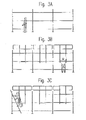
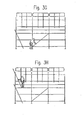
- guard rails are mounted in the scaffold sections in the manner shown in figures 3A to 3H .
- This method roughly comprises the following steps, corresponding to the figures, of:
- a scaffolding can thus be wholly erected from the bottom upward without the scaffolder having to work at height unsecured, i.e. without guard rail, for this purpose. This also applies for the dismantling of the scaffold, wherein the method is performed in reverse sequence, wherein the release can optionally also be operated manually.
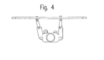
- Figure 4 shows a top view of the displacement of the guard rail according to the invention.
- the user has his hands on the standing rail elements of the framework which, irrespective of a width of the rail, are arranged at a distance from each other such that during displacement of the guard rail the arms of the user can be moved up and downward ergonomically, i.e. as straight as possible in forward direction.
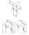
- Figure 5 shows an alternative embodiment of the guard rail of figure 1 which can likewise be applied in the scaffolding of figures 3A-H .
- the guard rail of this example largely corresponds to that of figure 1 , and corresponding parts are therefore provided with the same reference numerals.
- locking means 9 extend in this guard rail from both standing rail elements 1,2.
- the locking means can be foot-operated, so that the same person keeps his/her hands free for the desired manipulation of the guard rail, i.e. placing or disassembly thereof.
- both the locks 9 are in this case mutually coupled by means of a bracket 12 which extends therebetween and which can, if desired, be hand or foot-operated.
- the lock is tiltable by means of bracket 12 and can be moved out of the locking position of equilibrium shown in figure 5A and thereby released, see figure 5B .
- the movement of bracket 12 is bounded by means of stops 12A.
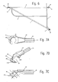
- FIG 6 also shows a guard rail which can be applied in a scaffolding for the purpose of safeguarding an end user of the scaffolding as well as a scaffolder against an undesirable fall from height.
- the guard rail comprises a lying rail element 1 with a proximal outer end 14 and a distal outer end 15.
- a standard tightenable rapid-action coupling 21 Arranged at the proximal outer end 14 is a standard tightenable rapid-action coupling 21 which is assumed sufficiently well known to a skilled person and therefore not further elucidated here.
- a hook body 22 Situated at the distal outer end 15 is a hook body 22 with a hook 23, see also figures 7A-7C .
- the rail element also comprises a first further rail element 2 and a second further rail element 3 which form substantially a right angle relative to each other at a shared corner point 13.
- a further hook body 32 bearing a further hook 33, see also figures 8A-8D .
- the further hook 33 and rapid-action coupling 21 serve for fixing to a first upright of a scaffolding, while first hook 23 couples to a following upright in the scaffolding.
- Round hollow tube profiles of aluminium are applied in this example for rail elements 1,2,3, although it is also possible to have recourse instead to another material, in particular steel.
- the hook bodies comprise in this example castings of cast steel, although another material can also be applied for this purpose, such as cast-iron or aluminium, and another manufacturing technique can optionally be chosen, such as for instance forging or milling.
- the guard rail also comprises a railing part 4 firmly connected to the other rail elements 1-3 in order to reduce the opening between these latter and impart more stability to the whole.
- Hook bodies 22,32 protrude into the above stated hollow tube profiles with their outer end 24,34 remote from the associated hook 23,33, see also figures 7A and 8A and are firmly connected thereto. Use can be made for this connection of welding, adhesion or deformation, or pop rivets or camping bushes can be applied for this purpose.
- a screw thread can optionally be provided on the outer end and in the tube outer end so that the parts can be screwed together.
- Hook 23 extends from the hook body shown in figures 7A-7B .
- a body cavity 26 which is bounded by a wall 25 and which opens on one side to receive therein a scaffold element of a scaffolding.
- the wall has here a first transition 25A and a second transition 25B, whereby in a first diagonal position as shown in figure 9A the hook fits in a U-shape round such a scaffold element 100 and can be laterally released again therefrom.
- the hook engages round scaffold element 100 in the second transition 25B over a greater part of the periphery of cavity 26 and can therefore no longer be released therefrom.
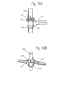
- the hook eventually takes up an at least substantially horizontal position, see figure 10B .
- this situation corresponds to that as shown in figure 7A , wherein the scaffold element lies substantially close-fittingly against wall 25 of cavity 26.
- the angle between the two diagonal positions corresponds to the angle between a centre line A of an almost cylindrical first passage through the body in the first transition 25A and a centre line B of an almost cylindrical second passage in the second transition 25B, see figure 7C .
- This angle is chosen such that the guard rail can be fully adjusted between the two diagonal positions from one scaffold section in order to be locked into or released from a scaffold section lying above with hook 23.
- the hook body is flattened on both sides to provide space for this adjustment.
- hook 23 is positioned on a cup-like holder 110.
- Such holders are provided at a regular pitch on scaffold element 100 and can be closed with a so called cuplok upper cup 115 which is freely axially movable and rotatable over the scaffold element but which, owing to a helical wall progression, clamps itself fixedly here to hook 23, see figures 10A and 10B .
- Hook body 22 comprises a flat flanged edge 27 which protrudes from wall 25 so as to thereby be able to support on such a holder 110.
- Provided in the flanged edge are two openings 28 lying respectively at 90 and 180 degrees relative to an axial longitudinal axis through body 22.
- wall 25 of hook 23 rises gradually on the closed side together with flanged edge 27 over a rounded portion 29 therein.
- the further hook 33 at corner point 13 of the guard rail extends in a similar manner from a hook body and is connected in similar manner.
- This hook body is shown in greater detail in figures 8A-C and comprises on a side remote from a free outer end 34 a round, half-open hook 33 which fits round a scaffold element and can be released therefrom again only at a right angle.
- a body cavity 36 inside the hook opens in a U-shape for this purpose and has a width a little larger than an external dimension of the scaffold element.
- the hook body comprises on an underside a protrusion 38 which engages either in one of the openings 28 in flanged edge 27 of the first hook element or, in the absence of a preceding guard rail in the scaffolding, in the cup-like holder 110 close to a scaffold junction, see figure 10A .
- the round hook 33 is provided on the upper side with an upright edge 37 which is enclosed in both cases by the cuplok upper cup 115 of the scaffold junction. This enclosing of hook 33 provides for a reliable absorption of force which influences a static behaviour of a scaffolding. Owing to the registration of protrusion 38 with openings 28 at 180 and 90 degrees in flanged edge 27 both hooks 23,33 will fit either straight or at a right angle into each other.
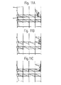
- the application of the described guard rail in a scaffolding is shown at successive stages in figures 11A-11F .
- the scaffolding comprises a series of successive scaffold elements in the form of uprights extending in a height direction. Successive levels in the scaffolding are separated from each other by floor parts 120 so that a matrix of separate scaffold sections is created.
- the floor parts rest here on girders in the scaffolding which are arranged transversely of the plane of the drawing and couple to the same system of uprights 100 anchored to an outside wall or the like.
- the whole scaffolding can thus be fully erected single-handedly from the bottom upward without the scaffolder having to work at height unsecured, i.e. without guard rail. This is likewise the case for dismantling of the scaffolding.
- a push-up frame can particularly be applied with two axially adjustable end parts, in particular slidable or telescopic end parts.
- a width of the guard rail is then adjustable and can be modified to a width to be spanned in the scaffold section.
- the rail is collapsible or can be disassembled into parts, for instance for the purpose of a small storage volume or transport volume.
Landscapes
- Engineering & Computer Science (AREA)
- Architecture (AREA)
- Mechanical Engineering (AREA)
- Civil Engineering (AREA)
- Structural Engineering (AREA)
- Ladders (AREA)
- Emergency Lowering Means (AREA)
Claims (6)
- Gerüst, umfassend stehende Elemente, die in regelmäßigen gegenseitigen Abständen angeordnet sind und sich in die Höhe erstrecken, um aufeinanderfolgende und übereinanderstehende Gerüstabschnitte dazwischen aufzunehmen, die durch wenigstens ein Bodenteil voneinander getrennt sind, ausgestattet mit einer Führungsschiene, die wenigstens ein liegendes Schienenelement (3, 4) umfasst, das sich zwischen wenigstens zwei stehenden Schienenelementen (1, 2) erstreckt, die ihrerseits mit dem liegenden Schienenelement verbunden sind, wobei die stehenden Schienenelemente mit manuell lösbaren Kupplungen (8) versehen sind zum Ankoppeln an ein Gerüstelement im darunterliegenden Gerüstabschnitt, und wobei die Führungsschiene versehen ist mit einer Verriegelungseinrichtung (9) an wenigstens einem der wenigstens zwei stehenden Schienenelemente zum Verriegeln der Führungsschiene relativ zum Gerüst, lösbar von Hand oder mittels des Fußes zum Zwecke des Freigebens der Führungsschiene vom Gerüst,
dadurch gekennzeichnet, dass
die stehenden Schienenelemente (1, 2) seitlich innerhalb der Reichweite des Arbeiters derart angeordnet sind, dass sie von ihm mit beiden Händen erfasst werden können, während sich das liegende Schienenelement (3, 4) seitlich außerhalb der stehenden Schienenelemente erstreckt, um den Gerüstabschnitt auf der ausgefahrenen Seite anzubinden, und dass die Verriegelungseinrichtung (9, 10) gleichzeitig mit dem Manipulieren der Führungsschiene von ein- und derselben Person betätigt werden kann. - Gerüst nach Anspruch 1, dadurch gekennzeichnet, dass sich die Verriegelungseinrichtung (9, 10) von beiden stehenden Schienenelementen (1, 2) aus erstreckt, und dass die Verriegelungseinrichtung auf beiden stehenden Schienenelementen gegenseitig angekoppelt werden können, insbesondere durch eine Konsole (12), die sich zwischen diesen beiden erstreckt.
- Gerüst nach Anspruch 1, dadurch gekennzeichnet, dass sich die Verriegelungseinrichtungen (9, 10) an wenigstens einem der beiden stehenden Schienenelemente befinden, und dass die Verriegelungseinrichtung mit einer Fußplatte (11) zur Fußbedienung versehen ist.
- Gerüst nach einem oder mehreren der vorausgegangenen Ansprüche, dadurch gekennzeichnet, dass die Kupplung zwei hängende Konsolen (8) umfasst, die ein liegendes Gerüstelement im darunterliegenden Gerüstabschnitt umfassen.
- Gerüst nach einem oder mehreren der vorausgegangenen Ansprüche, dadurch gekennzeichnet, dass die Breite der Führungsschiene (3, 4) justierbar ist.
- Gerüst nach einem oder mehreren der vorausgegangenen Ansprüche, dadurch gekennzeichnet, dass das liegende Schienenelement (3, 4) ein Teil eines Fachwerkes bildet.
Priority Applications (1)
| Application Number | Priority Date | Filing Date | Title |
|---|---|---|---|
| EP14153888.4A EP2730718B1 (de) | 2009-11-20 | 2010-09-24 | Baugerüst |
Applications Claiming Priority (3)
| Application Number | Priority Date | Filing Date | Title |
|---|---|---|---|
| NL2003841A NL2003841C2 (nl) | 2009-11-20 | 2009-11-20 | Steigerwerk, voorloopleuning en haaklichaam. |
| NL2004000A NL2004000C2 (nl) | 2009-12-21 | 2009-12-21 | Steigerwerk en voorloopleuning voor toepassing daarin. |
| PCT/NL2010/050620 WO2011062483A2 (en) | 2009-11-20 | 2010-09-24 | Scaffolding and guard rail for application therein |
Related Child Applications (2)
| Application Number | Title | Priority Date | Filing Date |
|---|---|---|---|
| EP14153888.4A Division EP2730718B1 (de) | 2009-11-20 | 2010-09-24 | Baugerüst |
| EP14153888.4A Division-Into EP2730718B1 (de) | 2009-11-20 | 2010-09-24 | Baugerüst |
Publications (2)
| Publication Number | Publication Date |
|---|---|
| EP2501880A2 EP2501880A2 (de) | 2012-09-26 |
| EP2501880B1 true EP2501880B1 (de) | 2014-05-21 |
Family
ID=43531778
Family Applications (2)
| Application Number | Title | Priority Date | Filing Date |
|---|---|---|---|
| EP10763888.4A Active EP2501880B1 (de) | 2009-11-20 | 2010-09-24 | Gerüst und führungsschiene in dem gerüst |
| EP14153888.4A Active EP2730718B1 (de) | 2009-11-20 | 2010-09-24 | Baugerüst |
Family Applications After (1)
| Application Number | Title | Priority Date | Filing Date |
|---|---|---|---|
| EP14153888.4A Active EP2730718B1 (de) | 2009-11-20 | 2010-09-24 | Baugerüst |
Country Status (2)
| Country | Link |
|---|---|
| EP (2) | EP2501880B1 (de) |
| WO (1) | WO2011062483A2 (de) |
Cited By (1)
| Publication number | Priority date | Publication date | Assignee | Title |
|---|---|---|---|---|
| EP3748107A1 (de) | 2019-06-04 | 2020-12-09 | Manfred Rolle | Montageadapter, sicherheitsgeländer, bausatz für ein baugerüst sowie baugerüst und verfahren hierfür |
Families Citing this family (3)
| Publication number | Priority date | Publication date | Assignee | Title |
|---|---|---|---|---|
| NL2006849C2 (nl) * | 2011-05-25 | 2012-11-27 | Harsco Infrastructure B V | Steigerwerk en voorloopleuning voor toepassing daarin. |
| DK178217B1 (da) * | 2014-10-10 | 2015-08-31 | Ulstrupsmeden Aps | Sikkerhedsrækværk |
| GB2565057B (en) * | 2017-07-28 | 2023-02-15 | Tag Industrial Scaffolding Ltd | Advanced guardrail coupling system and its method of use |
Family Cites Families (9)
| Publication number | Priority date | Publication date | Assignee | Title |
|---|---|---|---|---|
| FR2743103B1 (fr) * | 1995-12-27 | 1998-04-03 | Hussor Erecta Sa | Panneau garde-corps de securite, en particulier pour echafaudage multidirectionnel |
| DE20005629U1 (de) * | 2000-03-25 | 2000-06-29 | Krause-Werk GmbH & Co KG, 36304 Alsfeld | Strebe |
| DE10128595A1 (de) * | 2001-06-13 | 2002-12-19 | Peri Gmbh | Stirnseitengeländer |
| DE10305158A1 (de) * | 2003-02-08 | 2004-08-19 | Altrad Baumann Gmbh | Geländervorrichtung für ein Baugerüst |
| JP3996102B2 (ja) * | 2003-08-25 | 2007-10-24 | アルインコ株式会社 | 安全手摺 |
| JP2006291473A (ja) * | 2005-04-06 | 2006-10-26 | Sumitomo Metal Steel Products Inc | 先行手摺枠及び緊結式枠組足場 |
| GB0512597D0 (en) * | 2005-06-21 | 2005-07-27 | Ad & C Ltd | Climbing guard rail protection system for scaffolding towers |
| GB0517749D0 (en) * | 2005-09-01 | 2005-10-12 | Owens Andrew C | Guardrail attachment means for scaffolding towers |
| AU2009100475A4 (en) * | 2008-05-20 | 2009-10-01 | G. James Glass & Aluminium Pty Ltd | Scaffolding connector |
-
2010
- 2010-09-24 WO PCT/NL2010/050620 patent/WO2011062483A2/en not_active Ceased
- 2010-09-24 EP EP10763888.4A patent/EP2501880B1/de active Active
- 2010-09-24 EP EP14153888.4A patent/EP2730718B1/de active Active
Cited By (2)
| Publication number | Priority date | Publication date | Assignee | Title |
|---|---|---|---|---|
| EP3748107A1 (de) | 2019-06-04 | 2020-12-09 | Manfred Rolle | Montageadapter, sicherheitsgeländer, bausatz für ein baugerüst sowie baugerüst und verfahren hierfür |
| DE102019114913A1 (de) * | 2019-06-04 | 2020-12-10 | Manfred Rolle | Montageadapter, Sicherheitsgeländer, Bausatz für ein Baugerüst sowie Baugerüst und Verfahren hierfür |
Also Published As
| Publication number | Publication date |
|---|---|
| EP2730718B1 (de) | 2016-04-13 |
| WO2011062483A3 (en) | 2011-08-11 |
| WO2011062483A2 (en) | 2011-05-26 |
| EP2730718A1 (de) | 2014-05-14 |
| EP2501880A2 (de) | 2012-09-26 |
Similar Documents
| Publication | Publication Date | Title |
|---|---|---|
| US6053280A (en) | Hanging scaffold support | |
| AU2010346421B2 (en) | Scaffold and methods for installing or removing such a scaffold | |
| JP6305523B2 (ja) | 足場構造と共に使用するためのプラットフォームユニット | |
| EP1233122B1 (de) | Fassadengerüst | |
| EP3015623B1 (de) | Verfahren und vorrichtung zur montage eines lastturms | |
| MXPA05007420A (es) | Sistema de cimbra para losa de hormigon. | |
| US12024904B2 (en) | Support means, ceiling supports, ceiling framework system and method for removing a ceiling framework panel | |
| EP2501880B1 (de) | Gerüst und führungsschiene in dem gerüst | |
| US7735606B1 (en) | Scaffold support platform | |
| US20100025151A1 (en) | Integral safety system which can be used for construction | |
| US6799658B2 (en) | Mobile outrigger scaffolding system | |
| EP2527563B1 (de) | Gerüst und Geländer zur Verwendung mit diesem Gerüst | |
| AU2005254758A1 (en) | Fittings for builders' trestles | |
| US20110088237A1 (en) | Novel scaffolding apparatus and method | |
| KR101769041B1 (ko) | 작업발판 승강용 작업대 및 이를 포함하는 거푸집 시스템 | |
| US20050061582A1 (en) | Movable and repositionable safety guard rails for scaffolding | |
| KR102433546B1 (ko) | 슬라브 판넬 지지장치 | |
| US5615751A (en) | Scaffold system used with wood panels | |
| JPS6343356Y2 (de) | ||
| CN219327290U (zh) | 一种临边操作平台 | |
| JP2000129911A (ja) | 足場用開閉式床付布枠 | |
| CA2910141C (en) | Deck for a shoring tower | |
| CN216810864U (zh) | 脚手架工作平台 | |
| KR100583775B1 (ko) | 건축용 비계구조 | |
| RU2245430C1 (ru) | Устройство для возведения опалубки под перекрытие |
Legal Events
| Date | Code | Title | Description |
|---|---|---|---|
| PUAI | Public reference made under article 153(3) epc to a published international application that has entered the european phase |
Free format text: ORIGINAL CODE: 0009012 |
|
| 17P | Request for examination filed |
Effective date: 20120620 |
|
| AK | Designated contracting states |
Kind code of ref document: A2 Designated state(s): AL AT BE BG CH CY CZ DE DK EE ES FI FR GB GR HR HU IE IS IT LI LT LU LV MC MK MT NL NO PL PT RO SE SI SK SM TR |
|
| DAX | Request for extension of the european patent (deleted) | ||
| 17Q | First examination report despatched |
Effective date: 20130703 |
|
| GRAP | Despatch of communication of intention to grant a patent |
Free format text: ORIGINAL CODE: EPIDOSNIGR1 |
|
| INTG | Intention to grant announced |
Effective date: 20131220 |
|
| GRAS | Grant fee paid |
Free format text: ORIGINAL CODE: EPIDOSNIGR3 |
|
| GRAA | (expected) grant |
Free format text: ORIGINAL CODE: 0009210 |
|
| AK | Designated contracting states |
Kind code of ref document: B1 Designated state(s): AL AT BE BG CH CY CZ DE DK EE ES FI FR GB GR HR HU IE IS IT LI LT LU LV MC MK MT NL NO PL PT RO SE SI SK SM TR |
|
| REG | Reference to a national code |
Ref country code: GB Ref legal event code: FG4D |
|
| REG | Reference to a national code |
Ref country code: CH Ref legal event code: EP |
|
| REG | Reference to a national code |
Ref country code: AT Ref legal event code: REF Ref document number: 669701 Country of ref document: AT Kind code of ref document: T Effective date: 20140615 |
|
| REG | Reference to a national code |
Ref country code: IE Ref legal event code: FG4D |
|
| REG | Reference to a national code |
Ref country code: DE Ref legal event code: R096 Ref document number: 602010016276 Country of ref document: DE Effective date: 20140626 |
|
| REG | Reference to a national code |
Ref country code: NL Ref legal event code: T3 |
|
| REG | Reference to a national code |
Ref country code: AT Ref legal event code: MK05 Ref document number: 669701 Country of ref document: AT Kind code of ref document: T Effective date: 20140521 |
|
| REG | Reference to a national code |
Ref country code: LT Ref legal event code: MG4D |
|
| PG25 | Lapsed in a contracting state [announced via postgrant information from national office to epo] |
Ref country code: LT Free format text: LAPSE BECAUSE OF FAILURE TO SUBMIT A TRANSLATION OF THE DESCRIPTION OR TO PAY THE FEE WITHIN THE PRESCRIBED TIME-LIMIT Effective date: 20140521 Ref country code: IS Free format text: LAPSE BECAUSE OF FAILURE TO SUBMIT A TRANSLATION OF THE DESCRIPTION OR TO PAY THE FEE WITHIN THE PRESCRIBED TIME-LIMIT Effective date: 20140921 Ref country code: GR Free format text: LAPSE BECAUSE OF FAILURE TO SUBMIT A TRANSLATION OF THE DESCRIPTION OR TO PAY THE FEE WITHIN THE PRESCRIBED TIME-LIMIT Effective date: 20140822 Ref country code: NO Free format text: LAPSE BECAUSE OF FAILURE TO SUBMIT A TRANSLATION OF THE DESCRIPTION OR TO PAY THE FEE WITHIN THE PRESCRIBED TIME-LIMIT Effective date: 20140821 Ref country code: FI Free format text: LAPSE BECAUSE OF FAILURE TO SUBMIT A TRANSLATION OF THE DESCRIPTION OR TO PAY THE FEE WITHIN THE PRESCRIBED TIME-LIMIT Effective date: 20140521 |
|
| REG | Reference to a national code |
Ref country code: DE Ref legal event code: R082 Ref document number: 602010016276 Country of ref document: DE Representative=s name: DR. WEITZEL & PARTNER PATENT- UND RECHTSANWAEL, DE |
|
| PG25 | Lapsed in a contracting state [announced via postgrant information from national office to epo] |
Ref country code: SE Free format text: LAPSE BECAUSE OF FAILURE TO SUBMIT A TRANSLATION OF THE DESCRIPTION OR TO PAY THE FEE WITHIN THE PRESCRIBED TIME-LIMIT Effective date: 20140521 Ref country code: PL Free format text: LAPSE BECAUSE OF FAILURE TO SUBMIT A TRANSLATION OF THE DESCRIPTION OR TO PAY THE FEE WITHIN THE PRESCRIBED TIME-LIMIT Effective date: 20140521 Ref country code: ES Free format text: LAPSE BECAUSE OF FAILURE TO SUBMIT A TRANSLATION OF THE DESCRIPTION OR TO PAY THE FEE WITHIN THE PRESCRIBED TIME-LIMIT Effective date: 20140521 Ref country code: AT Free format text: LAPSE BECAUSE OF FAILURE TO SUBMIT A TRANSLATION OF THE DESCRIPTION OR TO PAY THE FEE WITHIN THE PRESCRIBED TIME-LIMIT Effective date: 20140521 Ref country code: HR Free format text: LAPSE BECAUSE OF FAILURE TO SUBMIT A TRANSLATION OF THE DESCRIPTION OR TO PAY THE FEE WITHIN THE PRESCRIBED TIME-LIMIT Effective date: 20140521 Ref country code: LV Free format text: LAPSE BECAUSE OF FAILURE TO SUBMIT A TRANSLATION OF THE DESCRIPTION OR TO PAY THE FEE WITHIN THE PRESCRIBED TIME-LIMIT Effective date: 20140521 |
|
| REG | Reference to a national code |
Ref country code: GB Ref legal event code: 732E Free format text: REGISTERED BETWEEN 20141106 AND 20141112 |
|
| REG | Reference to a national code |
Ref country code: DE Ref legal event code: R082 Ref document number: 602010016276 Country of ref document: DE Representative=s name: DR. WEITZEL & PARTNER PATENT- UND RECHTSANWAEL, DE Effective date: 20141113 Ref country code: DE Ref legal event code: R081 Ref document number: 602010016276 Country of ref document: DE Owner name: BRAND ENERGY HOLDINGS BV, NL Free format text: FORMER OWNER: HARSCO INFRASTRUCTURE B.V., HELMOND, NL Effective date: 20141113 |
|
| PG25 | Lapsed in a contracting state [announced via postgrant information from national office to epo] |
Ref country code: PT Free format text: LAPSE BECAUSE OF FAILURE TO SUBMIT A TRANSLATION OF THE DESCRIPTION OR TO PAY THE FEE WITHIN THE PRESCRIBED TIME-LIMIT Effective date: 20140922 |
|
| PG25 | Lapsed in a contracting state [announced via postgrant information from national office to epo] |
Ref country code: SK Free format text: LAPSE BECAUSE OF FAILURE TO SUBMIT A TRANSLATION OF THE DESCRIPTION OR TO PAY THE FEE WITHIN THE PRESCRIBED TIME-LIMIT Effective date: 20140521 Ref country code: RO Free format text: LAPSE BECAUSE OF FAILURE TO SUBMIT A TRANSLATION OF THE DESCRIPTION OR TO PAY THE FEE WITHIN THE PRESCRIBED TIME-LIMIT Effective date: 20140521 Ref country code: BE Free format text: LAPSE BECAUSE OF FAILURE TO SUBMIT A TRANSLATION OF THE DESCRIPTION OR TO PAY THE FEE WITHIN THE PRESCRIBED TIME-LIMIT Effective date: 20140521 Ref country code: CZ Free format text: LAPSE BECAUSE OF FAILURE TO SUBMIT A TRANSLATION OF THE DESCRIPTION OR TO PAY THE FEE WITHIN THE PRESCRIBED TIME-LIMIT Effective date: 20140521 Ref country code: DK Free format text: LAPSE BECAUSE OF FAILURE TO SUBMIT A TRANSLATION OF THE DESCRIPTION OR TO PAY THE FEE WITHIN THE PRESCRIBED TIME-LIMIT Effective date: 20140521 Ref country code: EE Free format text: LAPSE BECAUSE OF FAILURE TO SUBMIT A TRANSLATION OF THE DESCRIPTION OR TO PAY THE FEE WITHIN THE PRESCRIBED TIME-LIMIT Effective date: 20140521 |
|
| REG | Reference to a national code |
Ref country code: FR Ref legal event code: CA Effective date: 20150114 Ref country code: FR Ref legal event code: TP Owner name: BRAND ENERGY HOLDINGS B.V., NL Effective date: 20150114 |
|
| REG | Reference to a national code |
Ref country code: DE Ref legal event code: R097 Ref document number: 602010016276 Country of ref document: DE |
|
| PLBE | No opposition filed within time limit |
Free format text: ORIGINAL CODE: 0009261 |
|
| STAA | Information on the status of an ep patent application or granted ep patent |
Free format text: STATUS: NO OPPOSITION FILED WITHIN TIME LIMIT |
|
| 26N | No opposition filed |
Effective date: 20150224 |
|
| PG25 | Lapsed in a contracting state [announced via postgrant information from national office to epo] |
Ref country code: MC Free format text: LAPSE BECAUSE OF FAILURE TO SUBMIT A TRANSLATION OF THE DESCRIPTION OR TO PAY THE FEE WITHIN THE PRESCRIBED TIME-LIMIT Effective date: 20140521 Ref country code: IT Free format text: LAPSE BECAUSE OF FAILURE TO SUBMIT A TRANSLATION OF THE DESCRIPTION OR TO PAY THE FEE WITHIN THE PRESCRIBED TIME-LIMIT Effective date: 20140521 Ref country code: LU Free format text: LAPSE BECAUSE OF FAILURE TO SUBMIT A TRANSLATION OF THE DESCRIPTION OR TO PAY THE FEE WITHIN THE PRESCRIBED TIME-LIMIT Effective date: 20140924 |
|
| REG | Reference to a national code |
Ref country code: CH Ref legal event code: PL |
|
| REG | Reference to a national code |
Ref country code: DE Ref legal event code: R097 Ref document number: 602010016276 Country of ref document: DE Effective date: 20150224 |
|
| REG | Reference to a national code |
Ref country code: IE Ref legal event code: MM4A |
|
| PG25 | Lapsed in a contracting state [announced via postgrant information from national office to epo] |
Ref country code: LI Free format text: LAPSE BECAUSE OF NON-PAYMENT OF DUE FEES Effective date: 20140930 Ref country code: SI Free format text: LAPSE BECAUSE OF FAILURE TO SUBMIT A TRANSLATION OF THE DESCRIPTION OR TO PAY THE FEE WITHIN THE PRESCRIBED TIME-LIMIT Effective date: 20140521 Ref country code: CH Free format text: LAPSE BECAUSE OF NON-PAYMENT OF DUE FEES Effective date: 20140930 |
|
| PG25 | Lapsed in a contracting state [announced via postgrant information from national office to epo] |
Ref country code: IE Free format text: LAPSE BECAUSE OF NON-PAYMENT OF DUE FEES Effective date: 20140924 |
|
| PG25 | Lapsed in a contracting state [announced via postgrant information from national office to epo] |
Ref country code: SM Free format text: LAPSE BECAUSE OF FAILURE TO SUBMIT A TRANSLATION OF THE DESCRIPTION OR TO PAY THE FEE WITHIN THE PRESCRIBED TIME-LIMIT Effective date: 20140521 |
|
| PG25 | Lapsed in a contracting state [announced via postgrant information from national office to epo] |
Ref country code: MT Free format text: LAPSE BECAUSE OF FAILURE TO SUBMIT A TRANSLATION OF THE DESCRIPTION OR TO PAY THE FEE WITHIN THE PRESCRIBED TIME-LIMIT Effective date: 20140521 Ref country code: BG Free format text: LAPSE BECAUSE OF FAILURE TO SUBMIT A TRANSLATION OF THE DESCRIPTION OR TO PAY THE FEE WITHIN THE PRESCRIBED TIME-LIMIT Effective date: 20140521 Ref country code: CY Free format text: LAPSE BECAUSE OF FAILURE TO SUBMIT A TRANSLATION OF THE DESCRIPTION OR TO PAY THE FEE WITHIN THE PRESCRIBED TIME-LIMIT Effective date: 20140521 |
|
| PG25 | Lapsed in a contracting state [announced via postgrant information from national office to epo] |
Ref country code: HU Free format text: LAPSE BECAUSE OF FAILURE TO SUBMIT A TRANSLATION OF THE DESCRIPTION OR TO PAY THE FEE WITHIN THE PRESCRIBED TIME-LIMIT; INVALID AB INITIO Effective date: 20100924 Ref country code: TR Free format text: LAPSE BECAUSE OF FAILURE TO SUBMIT A TRANSLATION OF THE DESCRIPTION OR TO PAY THE FEE WITHIN THE PRESCRIBED TIME-LIMIT Effective date: 20140521 |
|
| REG | Reference to a national code |
Ref country code: FR Ref legal event code: PLFP Year of fee payment: 7 |
|
| REG | Reference to a national code |
Ref country code: FR Ref legal event code: PLFP Year of fee payment: 8 |
|
| PG25 | Lapsed in a contracting state [announced via postgrant information from national office to epo] |
Ref country code: MK Free format text: LAPSE BECAUSE OF FAILURE TO SUBMIT A TRANSLATION OF THE DESCRIPTION OR TO PAY THE FEE WITHIN THE PRESCRIBED TIME-LIMIT Effective date: 20140521 |
|
| REG | Reference to a national code |
Ref country code: FR Ref legal event code: PLFP Year of fee payment: 9 |
|
| PG25 | Lapsed in a contracting state [announced via postgrant information from national office to epo] |
Ref country code: AL Free format text: LAPSE BECAUSE OF FAILURE TO SUBMIT A TRANSLATION OF THE DESCRIPTION OR TO PAY THE FEE WITHIN THE PRESCRIBED TIME-LIMIT Effective date: 20140521 |
|
| P01 | Opt-out of the competence of the unified patent court (upc) registered |
Effective date: 20230602 |
|
| PGFP | Annual fee paid to national office [announced via postgrant information from national office to epo] |
Ref country code: DE Payment date: 20250919 Year of fee payment: 16 |
|
| PGFP | Annual fee paid to national office [announced via postgrant information from national office to epo] |
Ref country code: NL Payment date: 20250925 Year of fee payment: 16 |
|
| PGFP | Annual fee paid to national office [announced via postgrant information from national office to epo] |
Ref country code: BE Payment date: 20250925 Year of fee payment: 16 Ref country code: GB Payment date: 20250917 Year of fee payment: 16 |
|
| PGFP | Annual fee paid to national office [announced via postgrant information from national office to epo] |
Ref country code: FR Payment date: 20250922 Year of fee payment: 16 |