EP2501896B1 - Ausdehnungssystem für dehnbare röhren - Google Patents
Ausdehnungssystem für dehnbare röhren Download PDFInfo
- Publication number
- EP2501896B1 EP2501896B1 EP10832218.1A EP10832218A EP2501896B1 EP 2501896 B1 EP2501896 B1 EP 2501896B1 EP 10832218 A EP10832218 A EP 10832218A EP 2501896 B1 EP2501896 B1 EP 2501896B1
- Authority
- EP
- European Patent Office
- Prior art keywords
- launcher
- expansion cone
- resilient
- expansion
- expandable tubular
- Prior art date
- Legal status (The legal status is an assumption and is not a legal conclusion. Google has not performed a legal analysis and makes no representation as to the accuracy of the status listed.)
- Not-in-force
Links
Images


Classifications
-
- E—FIXED CONSTRUCTIONS
- E21—EARTH OR ROCK DRILLING; MINING
- E21B—EARTH OR ROCK DRILLING; OBTAINING OIL, GAS, WATER, SOLUBLE OR MELTABLE MATERIALS OR A SLURRY OF MINERALS FROM WELLS
- E21B43/00—Methods or apparatus for obtaining oil, gas, water, soluble or meltable materials or a slurry of minerals from wells
- E21B43/02—Subsoil filtering
- E21B43/10—Setting of casings, screens, liners or the like in wells
- E21B43/103—Setting of casings, screens, liners or the like in wells of expandable casings, screens, liners, or the like
- E21B43/105—Expanding tools specially adapted therefor
-
- Y—GENERAL TAGGING OF NEW TECHNOLOGICAL DEVELOPMENTS; GENERAL TAGGING OF CROSS-SECTIONAL TECHNOLOGIES SPANNING OVER SEVERAL SECTIONS OF THE IPC; TECHNICAL SUBJECTS COVERED BY FORMER USPC CROSS-REFERENCE ART COLLECTIONS [XRACs] AND DIGESTS
- Y10—TECHNICAL SUBJECTS COVERED BY FORMER USPC
- Y10T—TECHNICAL SUBJECTS COVERED BY FORMER US CLASSIFICATION
- Y10T29/00—Metal working
- Y10T29/49—Method of mechanical manufacture
- Y10T29/49805—Shaping by direct application of fluent pressure
Definitions
- expandable tubing is often used for casing, liners and the like.
- a tubular member is installed in a wellbore and subsequently expanded by displacing an expansion cone through the tubular member.
- the expansion cone may be pushed or pulled using mechanical means, such as by a support tubular coupled thereto, or driven by hydraulic pressure.
- the expansion cone imparts radial force to the inner surface of the tubular member.
- the tubular member plastically deforms, thereby permanently increasing both its inner and outer diameters. In other words, the tubular member expands radially.
- Expandable tubulars may also be used to repair, seal, or remediate existing casing that has been perforated, parted, corroded, or otherwise damaged since installation.
- Document WO 03/016669 discloses an apparatus for radially expanding tubular members according to the preamble of claim 1 including a segmented expansion cone.
- the present disclosure relates to apparatus and methods for expanding a tubular within a wellbore. More specifically, the apparatus includes a resilient launcher with an expansion cone for expanding the tubular within the wellbore.
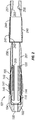
- FIG. 1A is a cross-section of a resilient launcher 101.
- the resilient launcher 101 is formed from a resilient material, such as polyurethane.
- the resilient launcher 101 includes a launcher portion 104 and a sleeve portion 106.
- the launcher portion 104 has a larger inner diameter than the sleeve portion 106 in order to accommodate an expansion cone 110, shown in FIG. 1B .
- the lower end of the launcher portion may include a guide nose 103 to aid passage through the wellbore and a port 130 to allow fluid passage through the resilient launcher 101.
- the resilient launcher may include a connection 105 to connect with additional resilient sleeves 201, as shown in FIG. 2 .
- the resilient launcher is configured to withstand internal pressure sufficient to hydraulically drive the expansion cone 110.
- the pressure necessary varies according to the mechanical properties and the diameter of the tubular being expanded, among various other factors. For an expansion process driven by hydraulic forces with little or no mechanical force applied, the pressure during expansion may range from about 1,000 psi to about 7,000 psi, with the primary factor being the diameter of the tubular being expanded.
- the resilient launcher 101 may include mechanical reinforcement 102, which may be, for example, carbon fiber, steel, fabric, and/or a mesh of fiber or metal.
- FIGS. 1A-1E The assembly of the expansion apparatus is illustrated in FIGS. 1A-1E .
- the expansion cone 110 is connected to a support member 120, which will connect to a work string during the expansion process.
- the work string may be, for example, drill pipe or coiled tubing.
- the expansion cone 110 is forced through the sleeve portion 106 and into the launcher portion 104.
- the sleeve portion 106 is sufficiently flexible to elastically stretch to accommodate the expansion cone 110.
- the resilient launcher 101 may be manufactured with the expansion cone 110 already disposed in the launcher portion 104 rather than inserted later.
- an expandable tubular 140 shown in FIG. 1D is placed around the sleeve portion 106 above the launcher portion 104, as shown in FIG. 1E .
- the expandable tubular 140 may include one or more sealing elements 141 for providing a seal against the inside of an existing casing or wellbore after the expansion process.
- the lower end 144 of the expandable tubular 140 may include a chamfer or round to avoid cutting the resilient launcher 101 as the expansion cone 110 moves upward during the expansion process.
- the inner diameter of the expandable tubular 140 may have a smaller diameter than the outer diameter of the sleeve portion 106 to provide a pressure fit.
- the inside of the expandable tubular 140 and/or the outside of the sleeve portion 106 may have ribs or other surface features to maintain their relative axial position while being placed in the wellbore.
- An adhesive may be applied to the inside of the expandable tubular 140 and/or the outside of the sleeve portion 106.
- the expandable tubular 140 may further include an upper connection 143 for connecting to another expandable tubular 240, which has a corresponding lower connection 243.
- the additional expandable tubular 240 may also include a sealing element 241 and an upper connection 244 for connecting to additional expandable tubulars.
- the resilient launcher 101 may also include an upper connection 105 for connecting to a lower connection 205 of another resilient sleeve 201, which will expand the additional expandable tubular 240.
- the upper and lower connections 105, 205 may be threaded.
- the upper and lower connection 105,205 may be complimentary frustoconical surfaces that are bonded by an adhesive or by heating until partially melting the complimentary frustoconical surfaces.
- the additional expandable tubular 240 may further include an upper connection 206 that connects to a lower connection 255 of an end piece 251.
- the end piece 251 includes an expansion cone catch 256 that will catch the expansion cone 110 after expanding the expandable tubulars 140, 240.
- the expansion cone catch 256 may be a shoulder or other restriction that prevents further upward axial movement of the expansion cone 110 relative to the end piece 251.
- the shoulder 256, or other restriction may be formed integrally within the uppermost expansion sleeve 201.
- FIGS. 3A-3C an expansion process using a resilient launcher 101 in accordance with one embodiment is shown.
- the resilient launcher 101 is positioned inside the wellbore 300 at the end of the work string 310.
- the wellbore 300 may be cased or open.
- fluid such as drilling mud
- the resilient launcher 101 is configured to expand a single section of expandable tubular 140 without additional resilient sleeves and expandable tubulars as in FIG. 2 .
- This embodiment is particularly suited for patching an existing cased wellbore.
- fluid may continue to be pumped from the surface through the port 130 into the wellbore 300.
- the fluid may be cement or other hardenable fluid.
- a wiper dart or ball 301 may be dropped from the surface to clean the fluid and plug the port 130 to allow pressure to build in the launcher portion 104 below the expansion cone 110, as shown in FIG. 3B .
- pump fluid 305 drives the expansion cone 110 upward into the sleeve portion 106 of the resilient launcher 101, which radially expands the expandable tubular 140 into contact with wellbore 300.
- the hydraulic expansion may be assisted by mechanically pulling upward on the expansion cone 110 from the surface via the work string 310. After the expansion cone 110 axially clears the now expanded tubular 140, the expansion cone 110 catches on the expansion cone catch 256, as shown in FIG. 3C . After catching the expansion cone 110, the work string 310 may be pulled upward to retrieve the expansion cone 110 and the resilient launcher 101.
- the expansion cone may be expandable.
- the expandable tubular may be expanded to a greater diameter while being able to pass through restrictions in the wellbore.
- the expandable expansion cone may be expanded within the launcher portion of the resilient launcher below the expandable tubular. Actuation of the expandable expansion cone may be carried out hydraulically because the launcher portion made of resilient material requires less force to expand than the metal launchers known in the prior art.
- Embodiments of the disclosure allow for hydraulically driven expansion of an expandable tubular in a wellbore using resilient sleeves to expand the expandable tubular to a greater diameter than the outside diameter of the expansion cone.
- This arrangement allows for a mechanically simple expansion apparatus that has a small pre-expansion outer diameter relative to the inner diameter of the post-expansion tubular. Accordingly, such an expansion apparatus can be deployed below wellbore restrictions while being able to expand the inner diameter of the expandable tubular to be equal or greater than the inner diameter of the wellbore restriction or existing liners.
- the expansion apparatus disclosed herein may be deployed using smaller rigs because of the low mechanical loads needed for the work string. Additionally, the work string may be tubing instead of drill pipe because of the reduced need for mechanical pull via the work string. This capability allows for the expansion apparatus disclosed herein to be deployed to a wider range of wells.
Landscapes
- Life Sciences & Earth Sciences (AREA)
- Engineering & Computer Science (AREA)
- Geology (AREA)
- Mining & Mineral Resources (AREA)
- Physics & Mathematics (AREA)
- Environmental & Geological Engineering (AREA)
- Fluid Mechanics (AREA)
- General Life Sciences & Earth Sciences (AREA)
- Geochemistry & Mineralogy (AREA)
- Pipe Accessories (AREA)
- Earth Drilling (AREA)
- Shaping Of Tube Ends By Bending Or Straightening (AREA)
Claims (8)
- Vorrichtung zum radialen Expandieren und plastischen Verformen eines expandierbaren rohrförmigen Elementes, umfassend:einen federnden Werfer (101), der einen Werferteil (104) und einen Hülsenteil (106) umfasst, wobei ein Innendurchmesser des Hülsenteils (106) kleiner als ein Innendurchmesser des Werferteils (104) ist;einen Expansionskegel (110), der mit einem Stützelement (120) verbunden ist und im Werferteil (104) des federnden Werfers (101) angeordnet ist, wobei der Werferteil (104) einen Durchlass (130) umfasst und wobei das Stützelement (120) und der Expansionskegel (110) dafür ausgelegt sind, das Pumpen von Fluid von der Oberfläche durch den Durchlass (130) zu ermöglichen, der im Werferteil (104) angeordnet ist;ein expandierbares Rohr (140), das um den Hülsenteil (106) und oberhalb des Werferteils (104) des federnden Werfers (101) angeordnet ist,wobei der Durchlass (130) unterhalb des Expansionskegels (110) abdichtbar ist, um dem Druck zu ermöglichen, sich im Werferteil (104) unterhalb des Expansionskegels (110) aufzubauen, so dass ein fortgesetztes Pumpen von Fluid durch das Stützelement (120) und den Expansionskegel (110) den Expansionskegel (110) nach oben in den Hülsenteil (106) des federnden Werfers (101) treibt, um so das expandierbare Rohr (140) radial zu expandieren; dadurch gekennzeichnet, dass eine Expansionskegelklinke (256) im Hülsenteil (106) oberhalb des expandierbaren Rohres (140) angeordnet ist, wobei die Expansionskegelklinke (256) die weitere Aufwärtsbewegung des Expansionskegels (110) relativ zum federnden Werfer (101) verhindert.
- Vorrichtung nach Anspruch 1, wobei der federnde Werfer (101) Polyurethan enthält.
- Vorrichtung nach Anspruch 2, wobei zumindest der Werferteil (104) des federnden Werfers (101) durch ein internes Gitter eines zweiten Materials verstärkt ist.
- Vorrichtung nach Anspruch 1, wobei der Expansionskegel (110) expandierbar ist.
- Vorrichtung nach Anspruch 4, wobei der Expansionskegel (110) als Reaktion auf hydraulischen Druck expandiert.
- Vorrichtung nach Anspruch 1, wobei das expandierbare Rohr (140) und der Hülsenteil (106) des federnden Werfers (101) durch einen Klebstoff miteinander verbunden sind.
- Verfahren, umfassend:
Platzieren einer Expansionsvorrichtung in einem Bohrloch am Ende eines Arbeitsstrangs, wobei die Expansionsvorrichtung umfasst:einen federnden Werfer (101), der einen Werferteil (104) und einen Hülsenteil (106) umfasst, wobei ein Innendurchmesser des Hülsenteils (106) kleiner als ein Innendurchmesser des Werferteils (104) ist,einen Expansionskegel (110), der im Werferteil (104) des federnden Werfers (101) angeordnet ist, und ein expandierbares Rohr (140), das rund um den Hülsenteil (106) und oberhalb des Werferteils (104) des federnden Werfers (101) angeordnet ist;Schließen eines Ports (130) im Werferteil (104) des federnden Werfers (101) unterhalb des Expansionskegels (110);Pumpen von Fluid in den Werferteil (104) des federnden Werfers (101) unterhalb des Expansionskegels (110), um den Expansionskegel (110) nach oben in den Hülsenteil (100) des federnden Werfers (101) zu treiben und das expandierbare Rohr (140) zu expandieren;Fangen des Expansionskegels (110) an einem oberen Ende der Expansionsvorrichtung durch einen Expansionskegel-Verschluss (256), der im Hülsenteil oberhalb des expandierbaren Rohres (140) angeordnet ist; undNach-oben-ziehen am Arbeitsstrang, um die Expansionsvorrichtung aus der Bohrung ohne das expandierbare Rohr (140) zu entfernen. - Verfahren nach Anspruch 7, ferner umfassend:
Expandieren des Expansionskegels (110) innerhalb des Werferteils (104) des federnden Werfers (101).
Applications Claiming Priority (2)
| Application Number | Priority Date | Filing Date | Title |
|---|---|---|---|
| US12/622,935 US8695698B2 (en) | 2009-11-20 | 2009-11-20 | Expansion system for expandable tubulars |
| PCT/US2010/057321 WO2011063170A2 (en) | 2009-11-20 | 2010-11-19 | Expansion system for expandable tubulars |
Publications (3)
| Publication Number | Publication Date |
|---|---|
| EP2501896A2 EP2501896A2 (de) | 2012-09-26 |
| EP2501896A4 EP2501896A4 (de) | 2015-12-30 |
| EP2501896B1 true EP2501896B1 (de) | 2018-05-30 |
Family
ID=44060347
Family Applications (1)
| Application Number | Title | Priority Date | Filing Date |
|---|---|---|---|
| EP10832218.1A Not-in-force EP2501896B1 (de) | 2009-11-20 | 2010-11-19 | Ausdehnungssystem für dehnbare röhren |
Country Status (4)
| Country | Link |
|---|---|
| US (1) | US8695698B2 (de) |
| EP (1) | EP2501896B1 (de) |
| BR (1) | BR112012012014A2 (de) |
| WO (1) | WO2011063170A2 (de) |
Families Citing this family (4)
| Publication number | Priority date | Publication date | Assignee | Title |
|---|---|---|---|---|
| GB2448924B (en) * | 2007-05-04 | 2010-09-15 | Dynamic Dinosaurs Bv | Methods for expanding tubular elements |
| US8695698B2 (en) | 2009-11-20 | 2014-04-15 | Enventure Global Technology, L.L.C. | Expansion system for expandable tubulars |
| PL3370550T3 (pl) | 2015-11-05 | 2019-08-30 | Philip Morris Products S.A. | Zhomogenizowany materiał tytoniowy z topliwym lipidem |
| CN106703731A (zh) * | 2016-11-22 | 2017-05-24 | 中海油能源发展股份有限公司 | 一种可快速对接膨胀锥的锁定密封装置及实施方法 |
Family Cites Families (16)
| Publication number | Priority date | Publication date | Assignee | Title |
|---|---|---|---|---|
| US3477506A (en) * | 1968-07-22 | 1969-11-11 | Lynes Inc | Apparatus relating to fabrication and installation of expanded members |
| US7357188B1 (en) * | 1998-12-07 | 2008-04-15 | Shell Oil Company | Mono-diameter wellbore casing |
| US7363984B2 (en) * | 1998-12-07 | 2008-04-29 | Enventure Global Technology, Llc | System for radially expanding a tubular member |
| GB2344606B (en) * | 1998-12-07 | 2003-08-13 | Shell Int Research | Forming a wellbore casing by expansion of a tubular member |
| AU783245B2 (en) * | 1999-11-01 | 2005-10-06 | Shell Internationale Research Maatschappij B.V. | Wellbore casing repair |
| US7100684B2 (en) * | 2000-07-28 | 2006-09-05 | Enventure Global Technology | Liner hanger with standoffs |
| GB0114872D0 (en) * | 2001-06-19 | 2001-08-08 | Weatherford Lamb | Tubing expansion |
| GB2409218B (en) * | 2001-08-20 | 2006-03-15 | Enventure Global Technology | Apparatus and method for radially expanding tubular members including an adjustable tubular expansion device |
| GB2422859B (en) * | 2001-11-12 | 2006-12-13 | Enventure Global Technology | Collapsible expansion cone |
| AU2003225001A1 (en) * | 2002-05-29 | 2003-12-19 | Eventure Global Technology | System for radially expanding a tubular member |
| CA2404315A1 (en) | 2002-09-20 | 2004-03-20 | Dean Edward Moan | Well servicing apparatus and method |
| CA2471051C (en) * | 2003-06-16 | 2007-11-06 | Weatherford/Lamb, Inc. | Borehole tubing expansion |
| GB0525410D0 (en) * | 2005-12-14 | 2006-01-25 | Weatherford Lamb | Expanding Multiple Tubular Portions |
| BRPI0715228A2 (pt) * | 2006-09-14 | 2013-06-18 | Shell Int Research | mÉtodo de expandir um elemento tubular |
| GB2448924B (en) * | 2007-05-04 | 2010-09-15 | Dynamic Dinosaurs Bv | Methods for expanding tubular elements |
| US8695698B2 (en) | 2009-11-20 | 2014-04-15 | Enventure Global Technology, L.L.C. | Expansion system for expandable tubulars |
-
2009
- 2009-11-20 US US12/622,935 patent/US8695698B2/en active Active
-
2010
- 2010-11-19 WO PCT/US2010/057321 patent/WO2011063170A2/en not_active Ceased
- 2010-11-19 BR BR112012012014A patent/BR112012012014A2/pt not_active IP Right Cessation
- 2010-11-19 EP EP10832218.1A patent/EP2501896B1/de not_active Not-in-force
Non-Patent Citations (1)
| Title |
|---|
| None * |
Also Published As
| Publication number | Publication date |
|---|---|
| BR112012012014A2 (pt) | 2016-05-10 |
| US20110120700A1 (en) | 2011-05-26 |
| WO2011063170A2 (en) | 2011-05-26 |
| EP2501896A2 (de) | 2012-09-26 |
| WO2011063170A3 (en) | 2011-07-28 |
| US8695698B2 (en) | 2014-04-15 |
| EP2501896A4 (de) | 2015-12-30 |
Similar Documents
| Publication | Publication Date | Title |
|---|---|---|
| US9163468B2 (en) | Expandable casing patch | |
| EP1127210B1 (de) | Verbinder für einen expandierbaren rohrstrang | |
| US8726985B2 (en) | Expanding a tubular element in a wellbore | |
| EP2013445B1 (de) | Expandierbarer liner-hänger | |
| CA2820220C (en) | Downhole release joint with radially expandable member | |
| US8100186B2 (en) | Expansion system for expandable tubulars and method of expanding thereof | |
| CA2820221C (en) | Downhole release joint with radially expandable member | |
| EP2817480B1 (de) | System und verfahren zur verbesserten abdichtung von bohrlochrohren | |
| US20090308594A1 (en) | Method for expanding a tubular element | |
| US8695698B2 (en) | Expansion system for expandable tubulars | |
| EP2202383A1 (de) | Verfahren zur Erweiterung eines röhrenförmigen Elements in einem Bohrloch | |
| RU2020120901A (ru) | Скважинная ремонтная система | |
| US10012058B2 (en) | Expansion system | |
| US9765598B2 (en) | Expansion system | |
| EP4707527A1 (de) | Bohrlochpackeranordnung | |
| CN113756778A (zh) | 复合完井管柱及其使用方法 |
Legal Events
| Date | Code | Title | Description |
|---|---|---|---|
| PUAI | Public reference made under article 153(3) epc to a published international application that has entered the european phase |
Free format text: ORIGINAL CODE: 0009012 |
|
| 17P | Request for examination filed |
Effective date: 20120613 |
|
| AK | Designated contracting states |
Kind code of ref document: A2 Designated state(s): AL AT BE BG CH CY CZ DE DK EE ES FI FR GB GR HR HU IE IS IT LI LT LU LV MC MK MT NL NO PL PT RO RS SE SI SK SM TR |
|
| DAX | Request for extension of the european patent (deleted) | ||
| A4 | Supplementary search report drawn up and despatched |
Effective date: 20151127 |
|
| RIC1 | Information provided on ipc code assigned before grant |
Ipc: E21B 43/10 20060101AFI20151123BHEP |
|
| STAA | Information on the status of an ep patent application or granted ep patent |
Free format text: STATUS: EXAMINATION IS IN PROGRESS |
|
| 17Q | First examination report despatched |
Effective date: 20170203 |
|
| GRAP | Despatch of communication of intention to grant a patent |
Free format text: ORIGINAL CODE: EPIDOSNIGR1 |
|
| STAA | Information on the status of an ep patent application or granted ep patent |
Free format text: STATUS: GRANT OF PATENT IS INTENDED |
|
| INTG | Intention to grant announced |
Effective date: 20180123 |
|
| GRAS | Grant fee paid |
Free format text: ORIGINAL CODE: EPIDOSNIGR3 |
|
| GRAA | (expected) grant |
Free format text: ORIGINAL CODE: 0009210 |
|
| STAA | Information on the status of an ep patent application or granted ep patent |
Free format text: STATUS: THE PATENT HAS BEEN GRANTED |
|
| RAP1 | Party data changed (applicant data changed or rights of an application transferred) |
Owner name: ENVENTURE GLOBAL TECHNOLOGY INC. |
|
| AK | Designated contracting states |
Kind code of ref document: B1 Designated state(s): AL AT BE BG CH CY CZ DE DK EE ES FI FR GB GR HR HU IE IS IT LI LT LU LV MC MK MT NL NO PL PT RO RS SE SI SK SM TR |
|
| REG | Reference to a national code |
Ref country code: GB Ref legal event code: FG4D |
|
| REG | Reference to a national code |
Ref country code: CH Ref legal event code: EP |
|
| REG | Reference to a national code |
Ref country code: AT Ref legal event code: REF Ref document number: 1003784 Country of ref document: AT Kind code of ref document: T Effective date: 20180615 |
|
| REG | Reference to a national code |
Ref country code: IE Ref legal event code: FG4D |
|
| REG | Reference to a national code |
Ref country code: DE Ref legal event code: R096 Ref document number: 602010051029 Country of ref document: DE |
|
| REG | Reference to a national code |
Ref country code: NL Ref legal event code: MP Effective date: 20180530 |
|
| REG | Reference to a national code |
Ref country code: LT Ref legal event code: MG4D |
|
| REG | Reference to a national code |
Ref country code: NO Ref legal event code: T2 Effective date: 20180530 |
|
| PG25 | Lapsed in a contracting state [announced via postgrant information from national office to epo] |
Ref country code: CY Free format text: LAPSE BECAUSE OF FAILURE TO SUBMIT A TRANSLATION OF THE DESCRIPTION OR TO PAY THE FEE WITHIN THE PRESCRIBED TIME-LIMIT Effective date: 20180530 Ref country code: LT Free format text: LAPSE BECAUSE OF FAILURE TO SUBMIT A TRANSLATION OF THE DESCRIPTION OR TO PAY THE FEE WITHIN THE PRESCRIBED TIME-LIMIT Effective date: 20180530 Ref country code: SE Free format text: LAPSE BECAUSE OF FAILURE TO SUBMIT A TRANSLATION OF THE DESCRIPTION OR TO PAY THE FEE WITHIN THE PRESCRIBED TIME-LIMIT Effective date: 20180530 Ref country code: ES Free format text: LAPSE BECAUSE OF FAILURE TO SUBMIT A TRANSLATION OF THE DESCRIPTION OR TO PAY THE FEE WITHIN THE PRESCRIBED TIME-LIMIT Effective date: 20180530 Ref country code: FI Free format text: LAPSE BECAUSE OF FAILURE TO SUBMIT A TRANSLATION OF THE DESCRIPTION OR TO PAY THE FEE WITHIN THE PRESCRIBED TIME-LIMIT Effective date: 20180530 Ref country code: BG Free format text: LAPSE BECAUSE OF FAILURE TO SUBMIT A TRANSLATION OF THE DESCRIPTION OR TO PAY THE FEE WITHIN THE PRESCRIBED TIME-LIMIT Effective date: 20180830 |
|
| PG25 | Lapsed in a contracting state [announced via postgrant information from national office to epo] |
Ref country code: RS Free format text: LAPSE BECAUSE OF FAILURE TO SUBMIT A TRANSLATION OF THE DESCRIPTION OR TO PAY THE FEE WITHIN THE PRESCRIBED TIME-LIMIT Effective date: 20180530 Ref country code: HR Free format text: LAPSE BECAUSE OF FAILURE TO SUBMIT A TRANSLATION OF THE DESCRIPTION OR TO PAY THE FEE WITHIN THE PRESCRIBED TIME-LIMIT Effective date: 20180530 Ref country code: LV Free format text: LAPSE BECAUSE OF FAILURE TO SUBMIT A TRANSLATION OF THE DESCRIPTION OR TO PAY THE FEE WITHIN THE PRESCRIBED TIME-LIMIT Effective date: 20180530 Ref country code: GR Free format text: LAPSE BECAUSE OF FAILURE TO SUBMIT A TRANSLATION OF THE DESCRIPTION OR TO PAY THE FEE WITHIN THE PRESCRIBED TIME-LIMIT Effective date: 20180831 |
|
| REG | Reference to a national code |
Ref country code: AT Ref legal event code: MK05 Ref document number: 1003784 Country of ref document: AT Kind code of ref document: T Effective date: 20180530 |
|
| PG25 | Lapsed in a contracting state [announced via postgrant information from national office to epo] |
Ref country code: NL Free format text: LAPSE BECAUSE OF FAILURE TO SUBMIT A TRANSLATION OF THE DESCRIPTION OR TO PAY THE FEE WITHIN THE PRESCRIBED TIME-LIMIT Effective date: 20180530 |
|
| PG25 | Lapsed in a contracting state [announced via postgrant information from national office to epo] |
Ref country code: AT Free format text: LAPSE BECAUSE OF FAILURE TO SUBMIT A TRANSLATION OF THE DESCRIPTION OR TO PAY THE FEE WITHIN THE PRESCRIBED TIME-LIMIT Effective date: 20180530 Ref country code: DK Free format text: LAPSE BECAUSE OF FAILURE TO SUBMIT A TRANSLATION OF THE DESCRIPTION OR TO PAY THE FEE WITHIN THE PRESCRIBED TIME-LIMIT Effective date: 20180530 Ref country code: PL Free format text: LAPSE BECAUSE OF FAILURE TO SUBMIT A TRANSLATION OF THE DESCRIPTION OR TO PAY THE FEE WITHIN THE PRESCRIBED TIME-LIMIT Effective date: 20180530 Ref country code: SK Free format text: LAPSE BECAUSE OF FAILURE TO SUBMIT A TRANSLATION OF THE DESCRIPTION OR TO PAY THE FEE WITHIN THE PRESCRIBED TIME-LIMIT Effective date: 20180530 Ref country code: EE Free format text: LAPSE BECAUSE OF FAILURE TO SUBMIT A TRANSLATION OF THE DESCRIPTION OR TO PAY THE FEE WITHIN THE PRESCRIBED TIME-LIMIT Effective date: 20180530 Ref country code: CZ Free format text: LAPSE BECAUSE OF FAILURE TO SUBMIT A TRANSLATION OF THE DESCRIPTION OR TO PAY THE FEE WITHIN THE PRESCRIBED TIME-LIMIT Effective date: 20180530 Ref country code: RO Free format text: LAPSE BECAUSE OF FAILURE TO SUBMIT A TRANSLATION OF THE DESCRIPTION OR TO PAY THE FEE WITHIN THE PRESCRIBED TIME-LIMIT Effective date: 20180530 |
|
| PG25 | Lapsed in a contracting state [announced via postgrant information from national office to epo] |
Ref country code: IT Free format text: LAPSE BECAUSE OF FAILURE TO SUBMIT A TRANSLATION OF THE DESCRIPTION OR TO PAY THE FEE WITHIN THE PRESCRIBED TIME-LIMIT Effective date: 20180530 Ref country code: SM Free format text: LAPSE BECAUSE OF FAILURE TO SUBMIT A TRANSLATION OF THE DESCRIPTION OR TO PAY THE FEE WITHIN THE PRESCRIBED TIME-LIMIT Effective date: 20180530 |
|
| REG | Reference to a national code |
Ref country code: DE Ref legal event code: R097 Ref document number: 602010051029 Country of ref document: DE |
|
| PLBE | No opposition filed within time limit |
Free format text: ORIGINAL CODE: 0009261 |
|
| STAA | Information on the status of an ep patent application or granted ep patent |
Free format text: STATUS: NO OPPOSITION FILED WITHIN TIME LIMIT |
|
| 26N | No opposition filed |
Effective date: 20190301 |
|
| PG25 | Lapsed in a contracting state [announced via postgrant information from national office to epo] |
Ref country code: SI Free format text: LAPSE BECAUSE OF FAILURE TO SUBMIT A TRANSLATION OF THE DESCRIPTION OR TO PAY THE FEE WITHIN THE PRESCRIBED TIME-LIMIT Effective date: 20180530 |
|
| REG | Reference to a national code |
Ref country code: DE Ref legal event code: R119 Ref document number: 602010051029 Country of ref document: DE |
|
| REG | Reference to a national code |
Ref country code: CH Ref legal event code: PL |
|
| PG25 | Lapsed in a contracting state [announced via postgrant information from national office to epo] |
Ref country code: MC Free format text: LAPSE BECAUSE OF FAILURE TO SUBMIT A TRANSLATION OF THE DESCRIPTION OR TO PAY THE FEE WITHIN THE PRESCRIBED TIME-LIMIT Effective date: 20180530 Ref country code: LU Free format text: LAPSE BECAUSE OF NON-PAYMENT OF DUE FEES Effective date: 20181119 |
|
| REG | Reference to a national code |
Ref country code: BE Ref legal event code: MM Effective date: 20181130 |
|
| REG | Reference to a national code |
Ref country code: IE Ref legal event code: MM4A |
|
| PG25 | Lapsed in a contracting state [announced via postgrant information from national office to epo] |
Ref country code: LI Free format text: LAPSE BECAUSE OF NON-PAYMENT OF DUE FEES Effective date: 20181130 Ref country code: CH Free format text: LAPSE BECAUSE OF NON-PAYMENT OF DUE FEES Effective date: 20181130 |
|
| PG25 | Lapsed in a contracting state [announced via postgrant information from national office to epo] |
Ref country code: DE Free format text: LAPSE BECAUSE OF NON-PAYMENT OF DUE FEES Effective date: 20190601 Ref country code: FR Free format text: LAPSE BECAUSE OF NON-PAYMENT OF DUE FEES Effective date: 20181130 Ref country code: IE Free format text: LAPSE BECAUSE OF NON-PAYMENT OF DUE FEES Effective date: 20181119 |
|
| PG25 | Lapsed in a contracting state [announced via postgrant information from national office to epo] |
Ref country code: AL Free format text: LAPSE BECAUSE OF FAILURE TO SUBMIT A TRANSLATION OF THE DESCRIPTION OR TO PAY THE FEE WITHIN THE PRESCRIBED TIME-LIMIT Effective date: 20180530 Ref country code: BE Free format text: LAPSE BECAUSE OF NON-PAYMENT OF DUE FEES Effective date: 20181130 |
|
| PG25 | Lapsed in a contracting state [announced via postgrant information from national office to epo] |
Ref country code: MT Free format text: LAPSE BECAUSE OF NON-PAYMENT OF DUE FEES Effective date: 20181119 |
|
| PG25 | Lapsed in a contracting state [announced via postgrant information from national office to epo] |
Ref country code: TR Free format text: LAPSE BECAUSE OF FAILURE TO SUBMIT A TRANSLATION OF THE DESCRIPTION OR TO PAY THE FEE WITHIN THE PRESCRIBED TIME-LIMIT Effective date: 20180530 |
|
| PG25 | Lapsed in a contracting state [announced via postgrant information from national office to epo] |
Ref country code: PT Free format text: LAPSE BECAUSE OF FAILURE TO SUBMIT A TRANSLATION OF THE DESCRIPTION OR TO PAY THE FEE WITHIN THE PRESCRIBED TIME-LIMIT Effective date: 20180530 |
|
| PG25 | Lapsed in a contracting state [announced via postgrant information from national office to epo] |
Ref country code: HU Free format text: LAPSE BECAUSE OF FAILURE TO SUBMIT A TRANSLATION OF THE DESCRIPTION OR TO PAY THE FEE WITHIN THE PRESCRIBED TIME-LIMIT; INVALID AB INITIO Effective date: 20101119 Ref country code: MK Free format text: LAPSE BECAUSE OF NON-PAYMENT OF DUE FEES Effective date: 20180530 |
|
| PG25 | Lapsed in a contracting state [announced via postgrant information from national office to epo] |
Ref country code: IS Free format text: LAPSE BECAUSE OF FAILURE TO SUBMIT A TRANSLATION OF THE DESCRIPTION OR TO PAY THE FEE WITHIN THE PRESCRIBED TIME-LIMIT Effective date: 20180930 |
|
| PGFP | Annual fee paid to national office [announced via postgrant information from national office to epo] |
Ref country code: GB Payment date: 20231127 Year of fee payment: 14 |
|
| PGFP | Annual fee paid to national office [announced via postgrant information from national office to epo] |
Ref country code: NO Payment date: 20231129 Year of fee payment: 14 |
|
| PG25 | Lapsed in a contracting state [announced via postgrant information from national office to epo] |
Ref country code: NO Free format text: LAPSE BECAUSE OF NON-PAYMENT OF DUE FEES Effective date: 20241130 |
|
| GBPC | Gb: european patent ceased through non-payment of renewal fee |
Effective date: 20241119 |
|
| PG25 | Lapsed in a contracting state [announced via postgrant information from national office to epo] |
Ref country code: GB Free format text: LAPSE BECAUSE OF NON-PAYMENT OF DUE FEES Effective date: 20241119 |