EP2501980B1 - Anschlussvorrichtung - Google Patents
Anschlussvorrichtung Download PDFInfo
- Publication number
- EP2501980B1 EP2501980B1 EP10728220.4A EP10728220A EP2501980B1 EP 2501980 B1 EP2501980 B1 EP 2501980B1 EP 10728220 A EP10728220 A EP 10728220A EP 2501980 B1 EP2501980 B1 EP 2501980B1
- Authority
- EP
- European Patent Office
- Prior art keywords
- housing
- tooth
- section
- core
- blocking element
- Prior art date
- Legal status (The legal status is an assumption and is not a legal conclusion. Google has not performed a legal analysis and makes no representation as to the accuracy of the status listed.)
- Not-in-force
Links
- 230000000903 blocking effect Effects 0.000 claims description 57
- 238000003780 insertion Methods 0.000 claims description 34
- 230000037431 insertion Effects 0.000 claims description 34
- 230000007704 transition Effects 0.000 claims description 8
- 230000002093 peripheral effect Effects 0.000 claims 11
- 238000006073 displacement reaction Methods 0.000 description 6
- 238000000605 extraction Methods 0.000 description 4
- 238000005452 bending Methods 0.000 description 3
- 230000001419 dependent effect Effects 0.000 description 2
- 238000002347 injection Methods 0.000 description 2
- 239000007924 injection Substances 0.000 description 2
- 239000000463 material Substances 0.000 description 2
- 239000000243 solution Substances 0.000 description 2
- 229920000049 Carbon (fiber) Polymers 0.000 description 1
- 230000004888 barrier function Effects 0.000 description 1
- 230000005540 biological transmission Effects 0.000 description 1
- 238000000071 blow moulding Methods 0.000 description 1
- 239000004917 carbon fiber Substances 0.000 description 1
- 238000002485 combustion reaction Methods 0.000 description 1
- 150000001875 compounds Chemical class 0.000 description 1
- 238000010276 construction Methods 0.000 description 1
- 230000005489 elastic deformation Effects 0.000 description 1
- 238000001914 filtration Methods 0.000 description 1
- 239000003365 glass fiber Substances 0.000 description 1
- 238000001746 injection moulding Methods 0.000 description 1
- 238000004519 manufacturing process Methods 0.000 description 1
- 239000000155 melt Substances 0.000 description 1
- 230000000149 penetrating effect Effects 0.000 description 1
- 239000012783 reinforcing fiber Substances 0.000 description 1
- 238000003466 welding Methods 0.000 description 1
Images





Classifications
-
- F—MECHANICAL ENGINEERING; LIGHTING; HEATING; WEAPONS; BLASTING
- F16—ENGINEERING ELEMENTS AND UNITS; GENERAL MEASURES FOR PRODUCING AND MAINTAINING EFFECTIVE FUNCTIONING OF MACHINES OR INSTALLATIONS; THERMAL INSULATION IN GENERAL
- F16L—PIPES; JOINTS OR FITTINGS FOR PIPES; SUPPORTS FOR PIPES, CABLES OR PROTECTIVE TUBING; MEANS FOR THERMAL INSULATION IN GENERAL
- F16L37/00—Couplings of the quick-acting type
- F16L37/08—Couplings of the quick-acting type in which the connection between abutting or axially overlapping ends is maintained by locking members
- F16L37/12—Couplings of the quick-acting type in which the connection between abutting or axially overlapping ends is maintained by locking members using hooks, pawls, or other movable or insertable locking members
- F16L37/14—Joints secured by inserting between mating surfaces an element, e.g. a piece of wire, a pin, a chain
-
- F—MECHANICAL ENGINEERING; LIGHTING; HEATING; WEAPONS; BLASTING
- F16—ENGINEERING ELEMENTS AND UNITS; GENERAL MEASURES FOR PRODUCING AND MAINTAINING EFFECTIVE FUNCTIONING OF MACHINES OR INSTALLATIONS; THERMAL INSULATION IN GENERAL
- F16L—PIPES; JOINTS OR FITTINGS FOR PIPES; SUPPORTS FOR PIPES, CABLES OR PROTECTIVE TUBING; MEANS FOR THERMAL INSULATION IN GENERAL
- F16L37/00—Couplings of the quick-acting type
- F16L37/08—Couplings of the quick-acting type in which the connection between abutting or axially overlapping ends is maintained by locking members
- F16L37/084—Couplings of the quick-acting type in which the connection between abutting or axially overlapping ends is maintained by locking members combined with automatic locking
- F16L37/0842—Couplings of the quick-acting type in which the connection between abutting or axially overlapping ends is maintained by locking members combined with automatic locking by means of a ring which is split into a plurality of component parts which are held in place by means of a resilient ring member
-
- F—MECHANICAL ENGINEERING; LIGHTING; HEATING; WEAPONS; BLASTING
- F16—ENGINEERING ELEMENTS AND UNITS; GENERAL MEASURES FOR PRODUCING AND MAINTAINING EFFECTIVE FUNCTIONING OF MACHINES OR INSTALLATIONS; THERMAL INSULATION IN GENERAL
- F16L—PIPES; JOINTS OR FITTINGS FOR PIPES; SUPPORTS FOR PIPES, CABLES OR PROTECTIVE TUBING; MEANS FOR THERMAL INSULATION IN GENERAL
- F16L37/00—Couplings of the quick-acting type
- F16L37/08—Couplings of the quick-acting type in which the connection between abutting or axially overlapping ends is maintained by locking members
- F16L37/084—Couplings of the quick-acting type in which the connection between abutting or axially overlapping ends is maintained by locking members combined with automatic locking
- F16L37/098—Couplings of the quick-acting type in which the connection between abutting or axially overlapping ends is maintained by locking members combined with automatic locking by means of flexible hooks
- F16L37/0985—Couplings of the quick-acting type in which the connection between abutting or axially overlapping ends is maintained by locking members combined with automatic locking by means of flexible hooks the flexible hook extending radially inwardly from an outer part and engaging a bead, recess or the like on an inner part
- F16L37/0987—Couplings of the quick-acting type in which the connection between abutting or axially overlapping ends is maintained by locking members combined with automatic locking by means of flexible hooks the flexible hook extending radially inwardly from an outer part and engaging a bead, recess or the like on an inner part the flexible hook being progressively compressed by axial tensile loads acting on the coupling
-
- F—MECHANICAL ENGINEERING; LIGHTING; HEATING; WEAPONS; BLASTING
- F16—ENGINEERING ELEMENTS AND UNITS; GENERAL MEASURES FOR PRODUCING AND MAINTAINING EFFECTIVE FUNCTIONING OF MACHINES OR INSTALLATIONS; THERMAL INSULATION IN GENERAL
- F16L—PIPES; JOINTS OR FITTINGS FOR PIPES; SUPPORTS FOR PIPES, CABLES OR PROTECTIVE TUBING; MEANS FOR THERMAL INSULATION IN GENERAL
- F16L37/00—Couplings of the quick-acting type
- F16L37/08—Couplings of the quick-acting type in which the connection between abutting or axially overlapping ends is maintained by locking members
- F16L37/12—Couplings of the quick-acting type in which the connection between abutting or axially overlapping ends is maintained by locking members using hooks, pawls, or other movable or insertable locking members
- F16L37/14—Joints secured by inserting between mating surfaces an element, e.g. a piece of wire, a pin, a chain
- F16L37/142—Joints secured by inserting between mating surfaces an element, e.g. a piece of wire, a pin, a chain where the securing element is inserted tangentially
- F16L37/148—Joints secured by inserting between mating surfaces an element, e.g. a piece of wire, a pin, a chain where the securing element is inserted tangentially the securing element being flexible
Definitions
- the present invention relates to a connecting device for an annular outer groove having plug portion of a tubular or tubular conduit or a nozzle, having the features of the preamble of claim 1.
- connection device of this type comprises a housing into which the plug-in section can be inserted.
- the known connection device also has a blocking element with which the plug-in section inserted into the housing can be locked in the housing.
- the blocking element engages for locking the plug-in section in the housing into the outer groove of the plug-in section and into an annular inner groove formed in the housing.
- the blocking element can be pulled out of these through a housing opening substantially tangentially to the grooves.
- the locking element is preassembled in the inner groove and allowed in the preassembled state under elastic deflection, the insertion of the plug-in section in the housing, in which case the locking element engages in the outer groove.
- the locking element is secured in the preassembled state on the housing against displacement in the circumferential direction.
- the blocking element is provided with a band-shaped core and a plurality of teeth arranged along the core in the circumferential direction, each of which has an outer tooth portion cooperating with the inner groove in the inserted state and an inner groove cooperating with the outer groove in the inserted state Tooth section have.
- These inner and outer tooth portions are on opposite sides of the soul, wherein the soul at least between adjacent teeth in the Cross-section has a soul profile having a maximum diameter determined by a major direction, while the teeth in cross-section each having a tooth profile having a determined by a radially inner inner edge of the teeth Zahnhauptraum.
- the main direction of the soul and the main direction of the tooth are parallel to each other.
- connection devices which comprise a housing, a plug-in section and a blocking element, are, for example, from US 6,179,347 B1 and from the US 3,606,402 known.
- the present invention is concerned with the problem of providing an improved embodiment for a connecting device of the type mentioned, which is characterized in particular by a simplified handling and / or by an increased load capacity and reliability.
- the invention is based on the general idea of arranging the teeth of the locking element inclined in profile relative to the soul of the locking element. This is achieved by making the blocking element such that the main direction of the soul is inclined with respect to the direction of the tooth's main axis.
- the invention uses the knowledge that there is a bending stress on the soul during insertion of the plug-in section and in the transmission of tensile forces between the housing and plug-in section. By tilting the main direction of the soul towards the direction of the tooth, this can Bending stress can be significantly reduced, which reduces the load on the locking element and extends the durability of the locking element and thus improves the reliability of the connecting device.
- the core main direction is oriented so as to be inclined with respect to the axial direction, and then the core axial direction is inclined with respect to the axial direction in the one direction while the main axis direction is inclined with respect to the axial direction in the other direction.
- the blocking element may, according to an advantageous embodiment, have an outer end section lying outside the housing in the preassembled state. This outer end portion simplifies the handling of the connecting device, in particular for pulling out the locking element, that is, for releasing the connection between the housing and plug-in section.
- the blocking element between the outer end section and the region extending in the inner groove can now have a twisted transition section.
- the main direction of the blocking element profile is raised from the direction of the core of the main axis toward the outer end section with respect to the axial direction.
- the main direction of the locking element profile in the outer end portion may extend substantially parallel to the axial direction.
- the soul from the outer end portion to the first tooth may have a toothless core portion extending into the inner groove. It has been found that the provision of such a toothless core section considerably simplifies the extraction of the blocking element for unlocking the connection between the plug-in section and the housing.
- a cover which covers at least the housing opening radially.
- an unwanted access to the blocking element can be avoided.
- the ingress of dirt through the housing opening can be reduced in the grooves.
- said cover can also extend over an outer portion of the locking element abutting the housing, that is to say radially covering also said outer end portion.
- the securing device may have a recess arranged on the outside of the housing, into which engages a projection which projects inwardly from an outer end of the blocking element.
- a force acting in the circumferential direction positive connection between the housing and the blocking element is generated, which is the blocking element relative to Housing positioned.
- the projection simplifies the manual extraction of the locking element.
- At least one of the teeth can be compared with the other normal teeth with respect to its geometry and / or be different in its orientation towards the soul.
- the at least one special tooth is designed or arranged so that it is axially supported on the housing in the preassembled state or in the inserted state in the insertion direction of the plug-in section in the inner groove.
- the at least one special tooth can be designed or arranged so that it is supported in the inserted state with its inner tooth portion in the inner groove on the housing, while the other normal teeth are supported with their inner tooth portions exclusively in the outer groove on the plug portion.
- the outer groove transverse to the circumferential direction may have a ramp profile, which in the insertion of the
- Plug section drops.
- a targeted alignment of the support of the blocking element is generated at a tensile load between the housing and plug-in section. This orientation counteracts an erecting of the teeth, which would lead to a radial load and expansion of the housing.
- the outer groove at an inboard end of the ramp profile have a recess which is dimensioned so that the teeth are arranged with their inner tooth sections in the recess radially free-standing.
- the teeth can support radially only in the region of the ramp profile, which additionally reduces the tendency to erect the teeth in the event of a tensile load.
- the depression in the profile is dimensioned smaller than the inner tooth sections. This prevents the teeth with their inner tooth sections from penetrating into the depression to the bottom.
- the housing outside may have at least one circumferentially extending circumferential rib, resulting in a significant stiffening of the housing.
- the connecting device for the tensile load is stiffened.
- the circumferential rib may be arranged on a plug-in opening for insertion of the plug-in portion having free end of the housing.
- at least two axially spaced circumferential ribs are provided, which improves the stiffening of the housing, in particular in the region of the free end.
- the inner groove is arranged axially between two such circumferential ribs.
- the housing is stiffened and stabilized targeted in the inner groove.
- a plurality of longitudinally extending longitudinal ribs may be provided on the outside of the housing, which in particular each connect at least two circumferential ribs to one another.
- the longitudinal ribs provide for an intensive stiffening of the housing, especially in the region of the inner groove.
- connection device 1 comprises a housing 2 and a blocking element 3.
- the connection device 1 is provided for producing a connection for a plug-in section 4.
- the plug-in section 4 is designed as a nozzle in the embodiments shown here. It is also possible to design the plug-in section 4 as a tubular or tubular conduit or to design it as an end section of a hose or a pipe. This plug-in section 4 has on its outer side an annular outer groove 5.
- connection device 1 is preferably used in motor vehicles, e.g. in a fresh air system of the vehicle for supplying an internal combustion engine of the vehicle with fresh air.
- the plug-in section 4, in particular in the form of the nozzle, can be arranged in a special embodiment on a suction module, in particular a fresh air system, or on a filter housing, in particular for air filtration, eg in a fresh air system, for example screwed, welded or clipped.
- a suction module in particular a fresh air system
- a filter housing in particular for air filtration, eg in a fresh air system, for example screwed, welded or clipped.
- the plug-in section 4, for example in the form of the nozzle is integrally formed, for example by means of plastic injection molding, on the suction module or on the filter housing.
- the housing 2 is designed such that the plug-in section 4 can be inserted into the housing 2. Furthermore, the housing 2 has on its inside an annular inner groove 6.
- the housing 2 is designed sleeve-shaped. It can be designed as a nozzle. Likewise, it can be used as an end piece for a in Fig. 1 be indicated with a broken line indicated tubular or tubular conduit 7.
- Said line 7 may, for example, be designed as a blow molding, which can be connected to the front side of the housing 2.
- a compound is, for example, a welded joint, in particular a friction-welded connection.
- the housing is provided at its end remote from the blocking element 3 with a connection region 8, which is particularly suitable for producing a friction-welded connection.
- this connection region 8 comprises an axial annular groove 9 which has a projection 10 projecting into the groove 9 at the base of the groove, which projection is spaced apart both from an inner wall 11 and from an outer wall 12 of the groove 9. During friction welding, this projection 10 melts at least partially, as a result of which the gaps between the projection 10 and the walls 11, 12 are at least partially filled.
- the blocking element 3 is used to lock the inserted into the housing 2 plug-in portion 4 on the housing 2.
- the blocking element 3 engages on the one hand in the outer groove 5 of the male portion 4 and on the other hand in the inner groove 6 of the housing 2 a.
- the housing 2 has an at least in the Fig. 2 . 3 and 7 recognizable housing opening 13, which passes through the housing 2 radially. Through this housing opening 13 through the locking element 3 can be pulled out of the inner groove 6 and out of the outer groove 5.
- the locking element 3 from the connecting device 1 the latching produced by means of the locking element 3 between plug-in section. 4 and housing 2 are released, whereby the connection is released and the plug-in portion 4 can be pulled out of the housing 2.
- the blocking element 3 is also preassembled in the inner groove 6. That is, the blocking element 3 can be mounted in the inner groove 6 so that it remains in the inner groove 6 and the housing 2 even if there is no plug-in portion 4. In this preassembled state, the blocking element 3 allows the plug-in section 4 to be inserted into the housing 2. This results in an elastic deformation or deflection of the blocking element 3 and in a latching with the outer groove 5 when the plug-in section 4 reaches an intended insertion depth.
- a seal 14 is shown, which, for example, can be configured as an O-ring.
- the seal 14 is inserted into a further, formed on the inside of the housing 2 annular inner groove 15 which is spaced from the locking element 3 associated with the inner groove 6 and positioned between said inner groove 6 and the terminal portion 8.
- This displacement protection of the locking element 3 can be realized by means of a securing device 17.
- This securing device 17 is arranged on the outside of the housing 2. It secures the locking element 3 against displacement relative to the housing 2 in the circumferential direction 16 at least in the in Fig. 2 indicated by an arrow extension direction 18th
- the securing device 17 expediently comprises an outer stop 19, which is arranged on the outside of the housing 2. In the preassembled state, this outer stop 19 is located opposite an outer end 20 of the blocking element 3 in the extension direction 18. Particularly expedient is the embodiment shown here, in which the securing device 17 is further equipped with a receiving pocket 21, which is also arranged on the outside of the housing 2. In the preassembled state, the outer end 20 of the locking element 3 is inserted into this receiving pocket 21. Appropriately, the above-mentioned outer stop 19 may be formed in this receiving pocket 21. Accordingly, the outer end 20 is in the preassembled state within the receiving pocket 21 the outer stopper 19 in the circumferential direction 16 opposite.
- the receiving pocket 21 is open on one axial side.
- the axial direction of the connecting device 1 is, for example, in Fig. 1 indicated by a double arrow and designated 22. It lies on a longitudinal central axis 23 of the housing 2 and the device 1.
- an axial opening 24 or open axial side 24 is formed, which in Fig. 1 can be seen and the example. Is remote from the connection section 8.
- the outer end 20 of the locking element 3 can be inserted through this opening 24, so through the open axial side 24 in the receiving pocket 21 and pulled out of it.
- the adjusting movement of the outer end 20 of the locking element 3 for securing in the receiving pocket 21 or for unlocking takes place axially, ie transversely to the circumferential direction 16 and thus transversely to the extension direction 18. In this way, a particularly effective securing of the locking element 3 is realized in the preassembled state.
- the receiving pocket 21 is designed to be closed relative to the open axial side 24, ie opposite the opening 24. Further, the receiving pocket 21 is extended in the circumferential direction, namely towards the housing opening 15 by means of a support web 25. According to the Fig. 1 . 8 and 9 can in the preassembled state an outer end portion 26 of the locking element 3, which has the outer end 20, come to this support web 25 axially to the plant. This results in an axial position assurance for the outer end section 26 for the preassembled state.
- the outer end section 26 can come into abutment essentially flat on the support web 25.
- Fig. 9 an embodiment in which the locking element 3 at its outer end portion 26 have an axially oriented recess 27 which is positioned so that in the pre-assembled state between the end portion 26 and the support web 25, a slot 28 is formed, which is dimensioned so that it can be used as a tool intervention.
- a flat screwdriver can be inserted to move by levering or twisting the end portion 26 of the receiving pocket 21 laterally, ie axially out.
- the securing device 17 may additionally or alternatively be equipped with a locking device 29 to the features described above.
- This locking device 29 comprises at least one detent 30.
- two such detents 30 are provided in each case.
- the respective catch 30 cooperates in the preassembled state with the outer end portion 26 of the locking element 3.
- the respective catch 30 hinders an axial displacement of this outer end section 26 relatively to the housing 2.
- the detents 30 are designed as ramps, which fall off in the direction of the support web 25.
- the blocking element 3 can according to the in Fig. 8 shown embodiment at its outer end portion 26 have an axially projecting portion 31. If, as here, two catches 30 are provided, the dimension of this axially projecting region 31 and the distance between the two catches 30 can be matched to one another such that in the preassembled state, the two catches 30 are arranged on both sides of the protruding region 31 and thereby provide an additional safeguard cause the locking element 3 in the circumferential direction 16, both in the extension direction 18 and in the in Fig. 2 indicated by an arrow insertion 32nd
- the outer end portion 26 of the locking element 3 may be provided with radial projections 33 and elevations 33, which may be designed, for example, in the manner of a ribbing.
- the projections 33 extend in the axial direction 22 or in the circumferential direction 16.
- this projections 33 can be provided in addition or as an alternative to such projections 33 according to FIG Fig. 8 in the outer end portion 26, and in particular in the axially projecting portion 31 at least one radial slot 34 may be provided.
- this slot 34 can be like the one in Fig. 9 shown slot 28 may be designed as a tool engagement, for example, to be able to move the end portion 26 axially out of its fuse by means of a flat screwdriver.
- a cover 35 which may optionally be provided.
- This cover 35 is located on the outside of the housing 2. It may be attached to the outside of the pocket 21 or integrally thereon be formed. In the preassembled state, this cover 35 can radially cover the blocking element 3 at least in the area of the housing opening 13.
- the cover 35 also covers the securing device 17 at least partially.
- the cover 35 may then be designed as a clip, which is attachable to the housing 2, in particular in the region of the housing opening 13. For example, by gripping, resilient Klipparme the housing opening 13 in the radial direction to engage behind a boundary of the housing opening 13.
- the housing opening 13 can be larger in the circumferential direction 16 than in the axial direction 22.
- the housing opening 13 is at least twice larger at least in the circumferential direction 16 than in the axial direction 22.
- a bending stress of the blocking element 3 can be achieved be reduced at a tangential extraction from the housing opening 13.
- the housing opening 13 in the circumferential direction 16 may be the same size as the outer portion 26 of the locking element 3 located in the preassembled state.
- the dimension in the circumferential direction 16 of the housing opening 13 on the one hand and the outer end portion 26 on the other hand are the same within the scope of conventional manufacturing tolerances about the same, whereby deviations of +/- 10% are tolerable.
- the housing opening 13 may, according to a preferred embodiment, have a first end 36 which is distally disposed in the preassembled state relative to an inboard end 37 of the locking element 3.
- This first End 36 of the housing opening 13 is designed as a radially extending first edge, which leads from the inner groove 6 directly radially to the outside of the housing 2.
- the housing opening 13 is bounded distally to the inboard end 37 of the locking element 3 with a radially oriented edge formed by the first end 36.
- the housing opening 13 has a second end 38, which is arranged in the preassembled state with respect to the inner end 37 of the locking element 3 proximal.
- This second end 38 forms a radially extending second edge of the housing opening 13, which also extends from the inside of the housing 2 directly radially to the outside of the housing 2.
- the inner end 37 proximal edge of the housing opening 13, so the second end 38 is radially oriented here as well.
- said second edge 38 and the second end 38 of the housing opening 13 may have a transverse web 39 which limits the inner groove 6 in the circumferential direction to the housing opening 13.
- the transverse web 39 thereby forms a stop for the blocking element 3 in the insertion direction 32.
- the locking element 3 has in the embodiments shown here a band-shaped core 40 and a plurality of teeth 41 which are adjacent to each other in the circumferential direction 16 and along the core 40 are arranged.
- the teeth 41 each have an outer tooth portion 42 and an inner tooth portion 43.
- the outer tooth portions 42 cooperate with the inner groove 5 of the plug-in portion 4, while the inner tooth portions 43 cooperate with the outer groove 6 of the housing 2.
- These inner tooth sections 43 and the outer tooth sections 42 protrude from the core 40 on opposite sides. They are according to the soul 40 according Fig. 11 essentially axially.
- the core 40 has at least between adjacent teeth 41 accordingly Fig. 1 in cross section a soul profile 44, which has a main direction 45.
- the main axial direction 45 is determined or defined by a maximum diameter 46 of the soul profile 44.
- the teeth 41 have in cross-section in each case a tooth profile 47 which has a tooth main direction 48, this tooth main direction 48 being determined or defined by a radially inner tooth flank 49 of the respective tooth 41.
- the tooth main direction 48 essentially corresponds to a straight line, on which said inner edge 49 comes into abutment at at least two points or flat.
- the blocking element 3 is corresponding Fig. 11 now made so that the main body direction 45 with the tooth main direction 48 includes an angle 50.
- the main body direction 45 is inclined with respect to the tooth main direction 48.
- both the main tooth direction 48 and the main direction of the head 45 are inclined with respect to the axial direction 22.
- the main axial direction 45 is inclined in the direction of the axial direction 22 relative to the main tooth direction 48.
- the angle 50 between the main axial direction 45 and the main direction of the tooth 48 is selected to be so large that the axial direction 22 lies between the main tooth direction 48 and the main direction 45 of the main body.
- Corresponding Fig. 2 has the blocking element 3, the end portion 26 which rests in the preassembled state on the outside of the housing 2.
- the dimensioning of the locking element 3 is chosen so large in the circumferential direction 16 that the outer end portion 26 in the preassembled state, an inner end portion 51 of the locking element, which has the inner end 37 and which is located in the inner groove 6, overlaps in the circumferential direction 16 , hereby There is a radial overlap between the inner end portion 51 and the outer end portion 26th
- the outer end portion 26 may according to Fig. 4 a relative to the soul 40 enlarged profile. As a result, the grip of the outer end portion 26 is improved, which simplifies the manual operation of the securing element 3 for pulling out of the grooves 5, 6.
- the core 40 between the outer end portion 26 and a first tooth 52 may have a toothless core portion 53 that is large enough to extend into the inner groove 6.
- Fig. 2 is the entire toothless core portion 53 within the inner groove. 6
- the blocking element 3 can according to the Fig. 2 and 4 between the outer end portion 26 and the inside of the housing 2 and in the inner groove 6 extending region have a twisted transition section 54.
- This twisted transition section 54 is characterized in that in this transition section 54 a unspecified main direction of the locking element profile, starting from a direction parallel to the main direction 45 extending orientation toward the outer end portion 26 relative to the axial direction 22, preferably so far that the main direction of the locking element profile in the outer end portion 26 is oriented substantially parallel to the axial direction 22.
- the blocking element 3 in the region of its core 40 can run inclined with respect to the axial direction 22, while it runs parallel to the axial direction 22 in the region of the end section 26. This allows a particularly flat and compact design for the connection device. 1
- the first tooth 52 in the extension direction 18 can be facilitated with an insertion bevel, which facilitates the insertion of the locking element 3 into the housing 2 and / or has a pull-out bevel, which facilitates the removal of the locking element 3 from the housing 2.
- a last tooth 55 in the extension direction 18 can have an insertion bevel facilitating the insertion of the locking element 3 into the housing 2 and / or an extension bevel facilitating the removal of the locking element 3 from the housing 2.
- the core 40 may preferably be arranged with respect to the inner and outer tooth portions 42, 43 eccentric to the teeth 41.
- the soul profile 44 relative to the tooth profile 47 downwardly shifted from the center. This corresponds to a displacement or eccentricity of the core 40 in the direction of the outer tooth portions 42, which cooperate with the inner groove 6.
- the locking element 3 during insertion of the plug-in section 4 easier to avoid elastically in the inner groove 6.
- the dimensions in the circumferential direction 16 of the housing opening 13, the toothless core portion 53, the twisted transition portion 54 and the outer end portion 26 are each selected to be approximately equal.
- Fig. 10 can be removed that adjacent teeth 41 in the circumferential direction 16 have a comparatively large distance from each other. Said distance corresponds approximately to a tooth width measured in the circumferential direction. This results in a particularly high degree of flexibility and stability for the blocking element 3.
- FIGS. 5 and 6 can be removed that the blocking element 3, in particular with respect to its inner tooth portions 43 is preferably shaped so that a plurality of differently shaped outer grooves 5 can be secured sufficiently positive manner. So show the FIGS. 5 and 6 two different embodiments for the plug-in sections 4 and for the outer grooves 5 formed thereon. Fig. 5 also shows an alternative seal 14 '.
- the blocking element 3 may be injection molded from plastic, said injection molded part comprising both the core 40 and the teeth 41.
- the blocking element 3 can be made of a homogeneous plastic, so that the soul 40 and the teeth 41 have no material differences.
- an embodiment is conceivable in which the blocking element 3 is produced in that the teeth 41 are molded onto the core 40.
- the core 40 can then also be made in principle of plastic, preferably made of a plastic other than the teeth 41, or of another material. The same then applies to the outer end portion 26, which may also be molded onto the core 40 or integrally formed thereon.
- connection arrangement 56 which comprises the connection device 1 and the plug-in section 4 inserted therein.
- a recess 57 may be provided outside the housing 2 so that a projection 58, which protrudes inward at the outer end 20 of the locking element 3, engages in this recess 57. This results in an additional fixation of the locking element 3 in the circumferential direction 16.
- the projection 58 allows a simplified manual extraction of the locking element 3 for releasing the connection of the connecting device. 1
- the recess 57 is located within the receiving pocket 21, so that it is radially overlapped.
- the housing 2 may be stiffened by means of at least one circumferential rib 59.
- the respective circumferential rib 59 extends in the circumferential direction 16, suitably annular closed.
- the respective circumferential rib 59 is arranged on the outside of the housing 2.
- two such circumferential ribs 59 are provided, which are arranged axially spaced from one another.
- a plurality of longitudinal ribs 60 are provided, which are also arranged on the outside of the housing 2 and thereby extend in the longitudinal direction of the housing 2.
- the longitudinal ribs 60 are dimensioned so that they connect the two circumferential ribs 59 with each other. The one, in Fig.
- the viewer facing circumferential rib 59 is disposed at the free end of the housing 2, which has an insertion opening 61 for insertion of the plug-in section 4.
- the two circumferential ribs 59 on the housing 2 are preferably positioned so that they are located axially on both sides of the inner groove 6, so that the inner groove 6 is positioned axially between the two circumferential ribs 59.
- the housing 2 is stiffened in the region of the inner groove 6.
- the outer groove 5 of the plug-in section 4 can have a ramp profile 65 transversely to the circumferential direction 16, that is to say in the axial direction 22 or longitudinal direction 22.
- the ramp profile 65 is oriented so that it drops in a direction indicated by an arrow insertion 62 of the male section 4.
- the insertion direction 62 defines the relative movement of the plug-in section 4 relative to the housing 2 during the insertion of the plug-in section 4 into the housing 2.
- the ramp profile 65 causes the teeth 41 to remain largely in a predetermined orientation and supported.
- the ramp profile 65 has a ramp angle 63 which is a maximum of 45 °.
- the outer groove 5 is geometrically shaped such that it has a recess 64 at an inner end of the ramp profile 65.
- This recess 64 is expediently dimensioned so that the teeth 41 of the locking element 3 are arranged in the recess 64 and in the region of the recess 64 radially free-standing. That is, the inner tooth portions 43 of the teeth 41 may protrude partially into the recess 64 but are radially spaced from the radially inner bottom of the recess 64.
- This design has the consequence that the teeth 41 can be radially supported only on the ramp profile 65, so that the tendency for erection of the teeth 41 is additionally reduced.
- FIGS. 16 and 17 may according to a particularly advantageous embodiment, at least one "special" tooth 41 'over the other "normal” teeth 41 with respect to its geometry and / or with respect to its orientation to the soul 40 be different, so have a different angle between the tooth main direction 48 and main direction 45 soul.
- said special tooth 41 ' is different from the other normal teeth 41 both in its geometry and in its orientation with respect to the core 40. It is expedient for a plurality of such special teeth 41' to be provided along the locking element 3, but less than half of all the teeth altogether 41, 41 '. For example, only 10% or at most 10% of the teeth 41, 41 'are deviating from the other normal teeth 41.
- These different special teeth 41 ' are expediently distributed in the circumferential direction preferably uniformly spaced from each other along the locking element 3.
- the respective special tooth 41 ' is designed or arranged so that it is axially supported in the pre-assembled state and in particular in the inserted state in the insertion direction 62 in the inner groove 6 on the housing 2.
- the blocking element 3 moves axially relative to the housing 2, such that the other normal teeth 41 with their inner tooth portions 43 project axially beyond the inner groove 6 and thereby can jam between the housing 2 and the plug portion 4.
- the normal teeth 41 are axially supported with its inner tooth portion 43 exclusively in the outer groove 5 on the plug portion 4, while the special teeth 41 'on the inner groove 6 on the housing 2 and in the example also axially supported in the outer groove 5 on the plug-in section 4.
Landscapes
- Engineering & Computer Science (AREA)
- General Engineering & Computer Science (AREA)
- Mechanical Engineering (AREA)
- Quick-Acting Or Multi-Walled Pipe Joints (AREA)
- Gasket Seals (AREA)
- Snaps, Bayonet Connections, Set Pins, And Snap Rings (AREA)
- Connector Housings Or Holding Contact Members (AREA)
Description
- Die vorliegende Erfindung betrifft eine Anschlussvorrichtung für einen eine ringförmige Außennut aufweisenden Steckabschnitt einer schlauchförmigen oder rohrförmigen Leitung oder eines Stutzens, mit den Merkmalen des Oberbegriffs des Anspruchs 1.
- Aus der
EP 1 845 299 B1 ist eine Anschlussvorrichtung dieser Art bekannt. Sie umfasst ein Gehäuse, in welches der Steckabschnitt einsteckbar ist. Die bekannte Anschlussvorrichtung weist außerdem ein Sperrelement auf, mit dem der in das Gehäuse eingesteckte Steckabschnitt im Gehäuse arretierbar ist. Das Sperrelement greift zum Arretieren des Steckabschnitts im Gehäuse in die Außennut des Steckabschnitts und in eine im Gehäuse ausgebildete ringförmige Innennut ein. Das Sperrelement ist durch eine Gehäuseöffnung im Wesentlichen tangential zu den Nuten aus diesen herausziehbar. Ferner ist das Sperrelement in der Innennut vormontierbar und erlaubt im vormontierten Zustand unter elastischer Auslenkung das Einsstecken des Steckabschnitts in das Gehäuse, wobei dann das Sperrelement in die Außennut einrastet. Des Weiteren ist bei der Anschlussvorrichtung das Sperrelement im vormontierten Zustand am Gehäuse gegen ein Verschieben in der Umfangsrichtung gesichert. - Des Weiteren ist bei der bekannten Anschlussvorrichtung das Sperrelement mit einer bandförmigen Seele und mehreren, in der Umfangsrichtung benachbarten, entlang der Seele angeordneten Zähnen ausgestattet, die jeweils einen im eingesteckten Zustand mit der Innennut zusammenwirkenden äußeren Zahnabschnitt sowie einen im eingesteckten Zustand mit der Außennut zusammenwirkenden inneren Zahnabschnitt aufweisen. Diese inneren und äußeren Zahnabschnitte stehen an sich gegenüberliegenden Seiten von der Seele ab, wobei die Seele zumindest zwischen benachbarten Zähnen im Querschnitt ein Seelenprofil aufweist, das eine durch einen Maximaldurchmesser bestimmte Hauptrichtung aufweist, während die Zähne im Querschnitt jeweils ein Zahnprofil aufweisen, das eine durch eine radial innen liegende Innenflanke der Zähne bestimmte Zahnhauptrichtung besitzt. Bei der bekannten Anschlussvorrichtung verlaufen die Seelenhauptrichtung und die Zahnhauptrichtung parallel zueinander.
- Weitere Anschlussvorrichtungen, die ein Gehäuse, einen Steckabschnitt und ein Sperrelement umfassen, sind bspw. aus der
US 6,179,347 B1 und aus derUS 3,606,402 bekannt. - Die vorliegende Erfindung beschäftigt sich mit dem Problem, für eine Anschlussvorrichtung der eingangs genannten Art eine verbesserte Ausführungsform anzugeben, die sich insbesondere durch eine vereinfachte Handhabung und/oder durch eine erhöhte Belastbarkeit bzw. Zuverlässigkeit auszeichnet.
- Dieses Problem wird erfindungsgemäß durch den Gegenstand des unabhängigen Anspruchs gelöst. Vorteilhafte Ausführungsformen sind Gegenstand der abhängigen Ansprüche.
- Die Erfindung beruht auf dem allgemeinen Gedanken, die Zähne des Sperrelements im Profil gegenüber der Seele des Sperrelements geneigt anzuordnen. Erreicht wird dies dadurch, dass das Sperrelement so hergestellt wird, dass die Seelenhauptrichtung gegenüber der Zahnhauptrichtung geneigt ist. Die Erfindung nutzt hierbei die Erkenntnis, dass es beim Einsteckend des Steckabschnitts sowie bei der Übertragung von Zugkräften zwischen Gehäuse und Steckabschnitt zu einer Biegebeanspruchung der Seele kommt. Durch Neigen der Seelenhauptrichtung gegenüber der Zahnhauptrichtung kann diese Biegebeanspruchung signifikant reduziert werden, was die Belastung des Sperrelements reduziert und die Dauerhaltbarkeit des Sperrelements verlängert und somit die Zuverlässigkeit der Anschlussvorrichtung verbessert.
- Dabei hat sich als besonders vorteilhaft erwiesen, die Seelenhauptrichtung in Richtung zu einer Axialrichtung gegenüber der Zahnhauptrichtung zu neigen, wobei auch die Zahnhauptrichtung gegenüber der Axialrichtung geneigt ist. Bevorzugt ist die Seelenhauptrichtung so orientiert, dass sie auch gegenüber der Axialrichtung geneigt ist, wobei dann die Seelenhauptrichtung gegenüber der Axialrichtung in der einen Richtung geneigt ist, während die Zahnhauptrichtung gegenüber der Axialrichtung in der anderen Richtung geneigt ist.
- Das Sperrelement kann gemäß einer vorteilhaften Ausführungsform einen im vormontierten Zustand außen am Gehäuse anliegenden außen liegenden Endabschnitt aufweisen. Dieser außen liegende Endabschnitt vereinfacht die Handhabung der Anschlussvorrichtung, insbesondere zum Herausziehen des Sperrelements, also zum Lösen der Verbindung zwischen Gehäuse und Steckabschnitt.
- Gemäß einer besonders vorteilhaften Weiterbildung kann nun das Sperrelement zwischen dem außen liegenden Endabschnitt und dem in der Innennut verlaufenden Bereich einen verwundenen Übergangsabschnitt aufweisen. In diesem Übergangsabschnitt erfolgt eine Aufrichtung der Hauptrichtung des Sperrelementprofils ausgehend von der Seelenhauptrichtung in Richtung zum außen liegenden Endabschnitt gegenüber der Axialrichtung. Insbesondere kann sich die Hauptrichtung des Sperrelementprofils im außen liegenden Endabschnitt im Wesentlichen parallel zur Axialrichtung erstrecken. Dieser verwundene Übergangsabschnitt ermöglicht eine besonders raumsparende, kompakte Bauform für die Anschlussvorrichtung, da insbesondere ein flächiges Anliegen des außen liegenden Endabschnitts am Gehäuse realisierbar ist.
- Gemäß einer anderen vorteilhaften Ausführungsform kann die Seele vom außen liegenden Endabschnitt bis zum ersten Zahn einen sich bis in die Innennut hinein erstreckenden zahnlosen Seelenabschnitt aufweisen. Es hat sich gezeigt, dass durch die Bereitstellung eines derartigen zahnlosen Seelenabschnitts das Herausziehen des Sperrelements zum Entsichern der Verbindung zwischen Steckabschnitt und Gehäuse erheblich vereinfacht wird.
- Entsprechend einer anderen vorteilhaften Ausführungsform, die auch eine selbständige Lösung des vorliegenden Problems repräsentieren kann, kann außen am Gehäuse eine Abdeckung vorgesehen sein, die zumindest die Gehäuseöffnung radial abdeckt. Mit Hilfe einer derartigen Abdeckung kann zum Einen ein ungewollter Zugriff zum Sperrelement vermieden werden. Zum Anderen kann das Eindringen von Schmutz durch die Gehäuseöffnung in die Nuten vermindert werden. Insgesamt kann mit Hilfe der Abdeckung die Funktionalität sowie die Dauerhaltbarkeit der Anschlussvorrichtung verbessert werden. Entsprechend vorteilhaften Ausführungsformen kann sich besagte Abdeckung auch über einen außen am Gehäuse anliegenden Endabschnitt des Sperrelements erstrecken, also zusätzlich auch besagten außen liegenden Endabschnitt radial abdecken. Hierdurch wird die Sicherung vor einer ungewollten Betätigung des Sperrelements verbessern.
- Entsprechend einer anderen Ausführungsform kann die Sicherungseinrichtung eine außen am Gehäuse angeordnete Vertiefung aufweisen, in die ein Vorsprung eingreift, der von einem außenliegenden Ende des Sperrelements nach innen absteht. Hierdurch wird ein in Umfangsrichtung wirkender Formschluss zwischen dem Gehäuse und dem Sperrelement erzeugt, der das Sperrelement relativ zum Gehäuse positioniert. Darüber hinaus vereinfacht der Vorsprung das manuelle Herausziehen des Sperrelements. Somit kann durch diese Bauweise die Handhabung der Anschlussvorrichtung verbessert werden.
- Entsprechend einer alternativen bzw. selbständigen Lösung, die optional realisiert werden kann, und zwar zusätzlich zu wenigstens einem der vorstehend genannten Merkmale, und für die auch unabhängig Schutz beansprucht wird, kann zumindest einer der Zähne gegenüber den anderen normalen Zähnen hinsichtlich seiner Geometrie und/oder hinsichtlich seiner Ausrichtung gegenüber der Seele unterschiedlich sein. Insbesondere kann dabei vorgesehen sein, dass der wenigstens eine spezielle Zahn so gestaltet bzw. angeordnet ist, dass er sich im vormontierten Zustand bzw. im eingesteckten Zustand in der Einsteckrichtung des Steckabschnitts in der Innennut axial am Gehäuse abstützt. Durch diesen Vorschlag wird erreicht, dass sich das Sperrelement während des Steckvorgangs in Axialrichtung nicht so weit gegenüber dem Gehäuse verschieben kann, dass die anderen oder normalen Zähne, die radial nach innen aus der Innennut vorstehen, axial über den Rand der Innennut vorstehen können, was zu einer Verklemmung mit dem Steckabschnitt führen würde. Die hier vorgestellte Maßnahme führt somit zu einer erhöhten Zuverlässigkeit der Anschlussvorrichtung.
- Beispielsweise kann der wenigstens eine spezielle Zahn so gestaltet bzw. angeordnet sein, dass er sich im eingesteckten Zustand mit seinem inneren Zahnabschnitt in der Innennut am Gehäuse abstützt, während sich die anderen normalen Zähne mit ihren inneren Zahnabschnitten ausschließlich in der Außennut am Steckabschnitt abstützen.
- Bei einer anderen vorteilhaften Ausführungsform kann die Außennut quer zur Umfangsrichtung ein Rampenprofil aufweisen, das in der Einsteckrichtung des
- Steckabschnitts abfällt. Hierdurch wird eine gezielte Ausrichtung der Abstützung des Sperrelements bei einer Zugkraftbelastung zwischen Gehäuse und Steckabschnitt erzeugt. Diese Ausrichtung wirkt dabei einem Aufrichten der Zähne entgegen, die zu einer radialen Belastung und Aufweitung des Gehäuses führen würde.
- Vorteilhaft kann dabei die Außennut an einem innenliegenden Ende des Rampenprofils eine Vertiefung aufweisen, die so dimensioniert ist, dass die Zähne mit ihren inneren Zahnabschnitten in der Vertiefung radial freistehend angeordnet sind. Durch diese Maßnahme wird erreicht, dass sich die Zähne radial nur im Bereich des Rampenprofils abstützen können, was die Tendenz zur Aufrichtung der Zähne im Falle einer Zugbelastung zusätzlich reduziert. Besonders zweckmäßig ist dabei eine Ausführungsform, bei welcher die Vertiefung im Profil kleiner dimensioniert ist als die inneren Zahnabschnitte. So wird verhindert, dass die Zähne mit ihren inneren Zahnabschnitten in die Vertiefung bis zu deren Grund eindringen können.
- Bei einer anderen vorteilhaften Ausführungsform kann das Gehäuse außen zumindest eine sich in Umfangsrichtung erstreckende Umfangsrippe aufweisen, was zu einer signifikanten Aussteifung des Gehäuses führt. Hierdurch wird die Anschlussvorrichtung für die Zugbelastung versteift. Vorzugsweise kann die Umfangsrippe an einem die Einstecköffnung zum Einstecken des Steckabschnitts aufweisenden freien Ende des Gehäuses angeordnet sein. Bevorzugt sind zumindest zwei axial voneinander beabstandete Umfangsrippen vorgesehen, was die Aussteifung des Gehäuses, insbesondere im Bereich des freien Endes, verbessert.
- Von besonderem Vorteil ist eine Ausführungsform, bei welcher die Innennut axial zwischen zwei solchen Umfangsrippen angeordnet ist. Hierdurch wird das Gehäuse gezielt im Bereich der Innennut ausgesteift und stabilisiert.
- Optional können am Gehäuse außen mehrere sich in Längsrichtung erstreckende Längsrippen vorgesehen sein, die insbesondere jeweils zumindest zwei Umfangsrippen miteinander verbinden. Auch die Längsrippen sorgen für eine intensive Aussteifung des Gehäuses, insbesondere im Bereich der Innennut.
- Weitere wichtige Merkmale und Vorteile der Erfindung ergeben sich aus den Unteransprüchen, aus den Zeichnungen und aus der zugehörigen Figurenbeschreibung anhand der Zeichnungen.
- Bevorzugte Ausführungsbeispiele der Erfindung sind in den Zeichnungen dargestellt und werden in der nachfolgenden Beschreibung näher erläutert, wobei sich gleiche Bezugszeichen auf gleiche oder ähnliche oder funktional gleiche Bauteile beziehen.
- Es zeigen, jeweils schematisch,
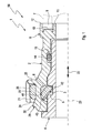
- Fig. 1
- einen halben Längsschnitt einer Anschlussvorrichtung,
- Fig. 2
- einen Querschnitt der Anschlussvorrichtung im Bereich eines Sperrelements,
- Fig. 3
- eine perspektivische Ansicht eines Gehäuses der Anschlussvorrichtung,
- Fig. 4
- eine perspektivische Ansicht des Sperrelements,
- Fig. 5
- eine teilweise perspektivische Detailansicht der Anschlussvorrichtung im Längsschnitt im Bereich des Sperrelements,
- Fig. 6
- eine Ansicht wie in
Fig. 5 , jedoch bei einer anderen Ausführungsform, - Fig. 7
- eine Teilansicht wie in
Fig. 3 , im Bereich einer Sicherungseinrichtung, - Fig. 8
- eine Seitenansicht der Anschlussvorrichtung im Bereich der Sicherungseinrichtung,
- Fig. 9
- eine Ansicht wie in
Fig. 8 , jedoch bei einer anderen Ausführungsform, - Fig. 10
- eine vergrößerte Detailansicht des Sperrelements,
- Fig. 11
- einen Längsschnitt des Sperrelements,
- Fig. 12
- einen Querschnitt der Anschlussvorrichtung im Bereich einer Sicherungseinrichtung,
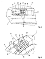
- Fig. 13
- eine perspektivische Ansicht eines Gehäuses der Anschlussvorrichtung,
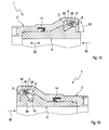
- Fig. 14 bis 17
- Längsschnitte der Anschlussvorrichtung im Bereich eines Sperrelements, bei verschiedenen Ausführungsformen.
- Entsprechend den
Fig. 1 bis 17 und insbesondere mit Bezug aufFig. 1 umfasst eine Anschlussvorrichtung 1 ein Gehäuse 2 sowie ein Sperrelement 3. Die Anschlussvorrichtung 1 ist zum Herstellen eines Anschlusses für einen Steckabschnitt 4 vorgesehen. Der Steckabschnitt 4 ist bei den hier gezeigten Ausführungsformen als Stutzen ausgestaltet. Ebenso ist es möglich, den Steckabschnitt 4 als schlauchförmige oder rohrförmige Leitung auszugestalten oder als Endabschnitt eines Schlauchs oder eines Rohrs auszugestalten. Dieser Steckabschnitt 4 weist an seiner Außenseite eine ringförmige Außennut 5 auf. - Die Anschlussvorrichtung 1 kommt bevorzugt in Kraftfahrzeugen zum Einsatz, z.B. in einer Frischluftanlage des Fahrzeugs zur Versorgung einer Brennkraftmaschine des Fahrzeugs mit Frischluft.
- Der Steckabschnitt 4, insbesondere in Form des Stutzens, kann bei einer speziellen Ausführungsform an einem Saugmodul, insbesondere einer Frischluftanlage, oder an einem Filtergehäuse, insbesondere zur Luftfiltration, z.B. in einer Frischluftanlage, angeordnet sein, z.B. verschraubt, verschweißt oder verclipst. Besonders vorteilhaft kann eine Ausführungsform sein, bei welcher der Steckabschnitt 4, z.B. in Form des Stutzens, integral, z.B. mittels Kunststoffspritzguss, am Saugmodul oder am Filtergehäuse ausgeformt ist.
- Das Gehäuse 2 ist so ausgestaltet, dass der Steckabschnitt 4 in das Gehäuse 2 einsteckbar ist. Ferner weist das Gehäuse 2 an seiner Innenseite eine ringförmige Innennut 6 auf. Das Gehäuse 2 ist hülsenförmig ausgestaltet. Es kann als Stutzen konzipiert sein. Ebenso kann es als Endstück für eine in
Fig. 1 mit unterbrochener Linie angedeutete rohrförmige oder schlauchförmige Leitung 7 konzipiert sein. - Besagte Leitung 7 kann bspw. als Blasformteil konzipiert sein, das stirnseitig mit dem Gehäuse 2 verbunden werden kann. Als Verbindung eignet sich bspw. eine Schweißverbindung, insbesondere eine Reibschweißverbindung. Im Beispiel der
Fig. 1 ist das Gehäuse an seinem vom Sperrelement 3 entfernten Ende mit einem Anschlussbereich 8 versehen, der sich in besonderer Weise zum Herstellen einer Reibschweißverbindung eignet. Insbesondere umfasst dieser Anschlussbereich 8 eine axiale Ringnut 9, die am Nutgrund einen in die Nut 9 vorstehenden Vorsprung 10 aufweist, der sowohl zu einer Innenwand 11 als auch zu einer Außenwand 12 der Nut 9 beabstandet ist. Beim Reibschweißen schmilzt dieser Vorsprung 10 zumindest teilweise auf, wodurch die Lücken zwischen dem Vorsprung 10 und den Wänden 11, 12, zumindest teilweise ausgefüllt werden. - Das Sperrelement 3 dient zum Arretieren des in das Gehäuse 2 eingesteckten Steckabschnitts 4 am Gehäuse 2. Hierzu greift das Sperrelement 3 einerseits in die Außennut 5 des Steckabschnitts 4 und andererseits in die Innennut 6 des Gehäuses 2 ein. Des Weiteren weist das Gehäuse 2 eine zumindest in den
Fig. 2 ,3 und7 erkennbare Gehäuseöffnung 13 auf, die das Gehäuse 2 radial durchsetzt. Durch diese Gehäuseöffnung 13 hindurch kann das Sperrelement 3 aus der Innennut 6 und aus der Außennut 5 herausgezogen werden. Durch Herausziehen des Sperrelements 3 aus der Anschlussvorrichtung 1 kann die mittels des Sperrelements 3 hergestellte Verrastung zwischen Steckabschnitt 4 und Gehäuse 2 aufgehoben werden, wodurch die Verbindung gelöst ist und der Steckabschnitt 4 aus dem Gehäuse 2 herausgezogen werden kann. - Das Sperrelement 3 ist außerdem in der Innennut 6 vormontierbar. Das heißt, das Sperrelement 3 kann in der Innennut 6 so montiert werden, dass es auch bei fehlendem Steckabschnitt 4 in der Innennut 6 bzw. am Gehäuse 2 verbleibt. In diesem vormontierten Zustand erlaubt das Sperrelement 3 das Einstecken des Steckabschnitts 4 in das Gehäuse 2. Hierbei kommt es zu einer elastischen Verformung bzw. Auslenkung des Sperrelements 3 sowie zu einer Verrastung mit der Außennut 5, wenn der Steckabschnitt 4 eine vorgesehene Einstecktiefe erreicht.
- In
Fig. 1 ist außerdem eine Dichtung 14 dargestellt, die bspw. als O-Ring ausgestaltet sein kann. Im Beispiel derFig. 1 ist die Dichtung 14 in eine weitere, an der Innenseite des Gehäuses 2 ausgebildete ringförmige Innennut 15 eingesetzt, die beabstandet zu der dem Sperrelement 3 zugeordneten Innennut 6 angeordnet und zwischen besagter Innennut 6 und dem Anschlussabschnitt 8 positioniert ist. - Im vormontierten Zustand ist das Sperrelement 3 am Gehäuse 2 gegen ein Verschieben in der Umfangsrichtung, die in
Fig. 2 durch einen Doppelpfeil angedeutet und mit 16 bezeichnet ist, gesichert. Diese Verschiebesicherung des Sperrelements 3 kann mit Hilfe einer Sicherungseinrichtung 17 realisiert werden. Diese Sicherungseinrichtung 17 ist dabei außen am Gehäuse 2 angeordnet. Sie sichert das Sperrelement 3 gegen eine Verschiebung relativ zum Gehäuse 2 in der Umfangsrichtung 16 zumindest in der inFig. 2 durch einen Pfeil angedeuteten Auszugsrichtung 18. - Die Sicherungseinrichtung 17 umfasst zweckmäßig einen Außenanschlag 19, der außen am Gehäuse 2 angeordnet ist. Im vormontierten Zustand liegt dieser Außenanschlag 19 einem außen liegenden Ende 20 des Sperrelements 3 in der Auszugsrichtung 18 gegenüber. Besonders zweckmäßig ist die hier gezeigte Ausführungsform, bei welcher die Sicherungseinrichtung 17 des Weiteren mit einer Aufnahmetasche 21 ausgestattet ist, die ebenfalls außen am Gehäuse 2 angeordnet ist. Im vormontierten Zustand ist in diese Aufnahmetasche 21 das außen liegende Ende 20 des Sperrelements 3 eingesteckt. Zweckmäßig kann in dieser Aufnahmetasche 21 der vorstehend genannte Außenanschlag 19 ausgebildet sein. Dementsprechend liegt das außen liegende Ende 20 im vormontierten Zustand innerhalb der Aufnahmetasche 21 dem Außenanschlag 19 in der Umfangsrichtung 16 gegenüber.
- Entsprechend den
Fig. 3 ,5 und7 bis 9 ist die Aufnahmetasche 21 gemäß bevorzugter Ausführungsformen an einer Axialseite offen. Die Axialrichtung der Anschlussvorrichtung 1 ist zum Beispiel inFig. 1 durch einen Doppelpfeil angedeutet und mit 22 bezeichnet. Sie liegt dabei auf einer Längsmittelachse 23 des Gehäuses 2 bzw. der Vorrichtung 1. Durch die axial offene Seite der Aufnahmetasche 21 wird eine axiale Öffnung 24 oder offene Axialseite 24 gebildet, die inFig. 1 erkennbar ist und die bspw. vom Anschlussabschnitt 8 abgewandt ist. Das außen liegende Ende 20 des Sperrelements 3 kann durch diese Öffnung 24, also durch die offene Axialseite 24 in die Aufnahmetasche 21 eingesteckt werden bzw. daraus herausgezogen werden. Die Verstellbewegung des außen liegenden Endes 20 des Sperrelements 3 zum Sichern in der Aufnahmetasche 21 bzw. zum Entsichern erfolgt dabei axial, also quer zur Umfangsrichtung 16 und somit quer zur Auszugsrichtung 18. Hierdurch wird eine besonders effektive Sicherung des Sperrelements 3 im vormontierten Zustand realisiert. - Bei den hier gezeigten Ausführungsformen ist die Aufnahmetasche 21 gegenüber der offenen Axialseite 24, also gegenüber der Öffnung 24 geschlossen ausgestaltet. Ferner ist die Aufnahmetasche 21 in der Umfangsrichtung, und zwar in Richtung zur Gehäuseöffnung 15 mit Hilfe eines Auflagestegs 25 verlängert. Entsprechend den
Fig. 1 ,8 und 9 kann im vormontierten Zustand ein außen liegender Endabschnitt 26 des Sperrelements 3, der das außen liegende Ende 20 aufweist, an diesem Auflagesteg 25 axial zur Anlage kommen. Hierdurch ergibt sich für den vormontierten Zustand eine axiale Lagesicherung für den außen liegenden Endabschnitt 26. - Gemäß
Fig. 8 kann der außen liegende Endabschnitt 26 im Wesentlichen flächig am Auflagesteg 25 zur Anlage kommen. Alternativ dazu zeigtFig. 9 eine Ausführungsform, bei welcher das Sperrelement 3 an seinem außen liegenden Endabschnitt 26 eine axial orientierte Einbuchtung 27 aufweisen, die so positioniert ist, dass sich im vormontierten Zustand zwischen dem Endabschnitt 26 und dem Auflagesteg 25 ein Schlitz 28 ausbildet, der so dimensioniert ist, dass er als Werkzeugeingriff verwendet werden kann. Beispielsweise kann in den Schlitz 28 ein flacher Schraubendreher eingesteckt werden, um durch Hebeln oder Verdrehen den Endabschnitt 26 aus der Aufnahmetasche 21 seitlich, also axial, herauszubewegen. - Die Sicherungseinrichtung 17 kann zusätzlich oder alternativ zu den vorbeschriebenen Merkmalen mit einer Rasteinrichtung 29 ausgestattet sein. Diese Rasteinrichtung 29 umfasst zumindest eine Raste 30. Bei den hier gezeigten Ausführungsformen sind jeweils zwei derartige Rasten 30 vorgesehen. Die jeweilige Raste 30 wirkt im vormontierten Zustand mit dem außen liegenden Endabschnitt 26 des Sperrelements 3 zusammen. Dabei behindert die jeweilige Raste 30 ein axiales Verstellen dieses außen liegenden Endabschnitts 26 relativ zum Gehäuse 2. Im Beispiel sind die Rasten 30 als Rampen ausgestaltet, die in Richtung zum Auflagesteg 25 abfallen.
- Das Sperrelement 3 kann gemäß der in
Fig. 8 gezeigten Ausführungsform an seinem außen liegenden Endabschnitt 26 einen axial abstehenden Bereich 31 aufweisen. Sofern wie hier zwei Rasten 30 vorgesehen sind, können die Abmessung dieses axial abstehenden Bereichs 31 und der Abstand zwischen den beiden Rasten 30 so aufeinander abgestimmt sein, dass im vormontierten Zustand die beiden Rasten 30 beiderseits des abstehenden Bereichs 31 angeordnet sind und dadurch eine zusätzliche Sicherung des Sperrelements 3 in der Umfangsrichtung 16 bewirken, und zwar sowohl in der Auszugsrichtung 18 als auch in der inFig. 2 durch einen Pfeil angedeuteten Einsteckrichtung 32. - Wie bspw. den
Fig. 4 ,8 und 9 entnehmbar ist, kann der außen liegende Endabschnitt 26 des Sperrelements 3 mit radialen Vorsprüngen 33 bzw. Erhebungen 33 ausgestattet sein, die bspw. nach Art einer Verrippung gestaltet sein können. Hierzu erstrecken sich die Vorsprünge 33 in Axialrichtung 22 oder in Umfangsrichtung 16. Durch diese Vorsprünge 33 wird die manuelle Greifbarkeit des Endabschnitts 26 signifikant verbessert. Des Weiteren kann zusätzlich oder alternativ zu derartigen Vorsprüngen 33 gemäßFig. 8 im außen liegenden Endabschnitt 26, und insbesondere im axial abstehenden Bereich 31 zumindest ein radialer Schlitz 34 vorgesehen sein. Auch dieser Schlitz 34 kann wie der inFig. 9 gezeigte Schlitz 28 als Werkzeugeingriff konzipiert sein, um bspw. mittels eines flachen Schraubendrehers den Endabschnitt 26 axial aus seiner Sicherung heraus bewegen zu können. - In
Fig. 2 ist mit unterbrochener Linie außerdem eine Abdeckung 35 angedeutet, die optional vorgesehen sein kann. Diese Abdeckung 35 befindet sich außen am Gehäuse 2. Sie kann außen an die Tasche 21 angesetzt sein oder integral daran ausgeformt sein. Im vormontierten Zustand kann diese Abdeckung 35 das Sperrelement 3 zumindest im Bereich der Gehäuseöffnung 13 radial abdecken. Im gezeigten Beispiel deckt die Abdeckung 35 auch die Sicherungseinrichtung 17 zumindest teilweise ab. Alternativ ist es ebenso möglich, die Abdeckung 35 bezüglich der Sicherungseinrichtung 17 an der gegenüberliegenden Seite der Gehäuseöffnung 13 am Gehäuse 2 anzubringen, bzw. integral dran auszuformen. Alternativ ist es ebenso möglich, die Abdeckung 35 bezüglich des Gehäuses 2 als separates Bauteil zu konzipieren. Insbesondere kann die Abdeckung 35 dann als Klipp konzipiert sein, der am Gehäuse 2, insbesondere im Bereich der Gehäuseöffnung 13 anbringbar ist. Beispielsweise durch greifende, federnde Klipparme die Gehäuseöffnung 13 in radialer Richtung, um eine Berandung der Gehäuseöffnung 13 zu hintergreifen. - Wie den hier gezeigten Ausführungsformen entnehmbar ist, kann die Gehäuseöffnung 13 in der Umfangsrichtung 16 größer sein als in der Axialrichtung 22. Insbesondere ist die Gehäuseöffnung 13 zumindest in der Umfangsrichtung 16 zumindest zweimal größer als in der Axialrichtung 22. Hierdurch kann eine Biegebeanspruchung des Sperrelements 3 bei einem tangentialen Herausziehen aus der Gehäuseöffnung 13 reduziert werden. Zweckmäßig kann die Gehäuseöffnung 13 in der Umfangsrichtung 16 gleich groß sein wie der im vormontierten Zustand außen liegende Endabschnitt 26 des Sperrelements 3. Die Abmessung in der Umfangsrichtung 16 der Gehäuseöffnung 13 einerseits und des außen liegenden Endabschnitts 26 andererseits sind dabei im Rahmen üblicher Herstellungstoleranzen gleich oder etwa gleich, wobei Maßabweichungen von +/- 10% tolerierbar sind.
- Die Gehäuseöffnung 13 kann entsprechend einer bevorzugten Ausführungsform ein erstes Ende 36 aufweisen, das im vormontierten Zustand relativ zu einem innenliegenden Ende 37 des Sperrelements 3 distal angeordnet ist. Dieses erste Ende 36 der Gehäuseöffnung 13 ist als radial verlaufender erster Rand ausgestaltet, der von der Innennut 6 direkt radial zu der Außenseite des Gehäuses 2 führt. Mit anderen Worten, die Gehäuseöffnung 13 ist distal zum innen liegenden Ende 37 des Sperrelements 3 mit einem radial orientierten Rand, der durch das erste Ende 36 gebildet ist, begrenzt. Ferner weist die Gehäuseöffnung 13 ein zweites Ende 38 auf, das im vormontierten Zustand bezüglich des innenliegenden Ende 37 des Sperrelements 3 proximal angeordnet ist. Dieses zweite Ende 38 bildet dabei einen radial verlaufenden zweiten Rand der Gehäuseöffnung 13, der sich ebenfalls von der Innenseite des Gehäuses 2 direkt radial zur Außenseite des Gehäuses 2 erstreckt. Somit ist auch hier der zum innen liegenden Ende 37 proximale Rand der Gehäuseöffnung 13, also das zweite Ende 38 radial orientiert.
- Zweckmäßig kann besagter zweiter Rand 38 bzw. das zweite Ende 38 der Gehäuseöffnung 13 einen Quersteg 39 aufweisen, der die Innennut 6 in der Umfangsrichtung zur Gehäuseöffnung 13 hin begrenzt. Der Quersteg 39 bildet dadurch einen Anschlag für das Sperrelement 3 in der Einschieberichtung 32.
- Wie insbesondere den
Fig. 4 ,10 und 11 zu entnehmen ist, besitzt das Sperrelement 3 bei den hier gezeigten Ausführungsformen eine bandförmige Seele 40 und mehrere Zähne 41, die in der Umfangsrichtung 16 zueinander benachbart und entlang der Seele 40 angeordnet sind. Die Zähne 41 weisen dabei jeweils einen äußeren Zahnabschnitt 42 sowie einen inneren Zahnabschnitt 43 auf. Im eingesteckten Zustand des Steckabschnitts 4 wirken die äußeren Zahnabschnitte 42 mit der Innennut 5 des Steckabschnitts 4 zusammen, während die inneren Zahnabschnitte 43 mit der Außennut 6 des Gehäuses 2 zusammenwirken. Diese inneren Zahnabschnitte 43 und die äußeren Zahnabschnitte 42 stehen von der Seele 40 an sich gegenüberliegenden Seiten ab. Dabei stehen sie von der Seele 40 gemäßFig. 11 im Wesentlichen axial ab. - Die Seele 40 besitzt zumindest zwischen benachbarten Zähnen 41 entsprechend
Fig. 1 im Querschnitt ein Seelenprofil 44, das eine Hauptrichtung 45 besitzt. Die Seelenhauptrichtung 45 wird dabei durch einen Maximaldurchmesser 46 des Seelenprofils 44 bestimmt bzw. definiert. Im Unterschied dazu besitzen die Zähne 41 im Querschnitt jeweils ein Zahnprofil 47, das eine Zahnhauptrichtung 48 aufweist, wobei diese Zahnhauptrichtung 48 durch eine radial innen liegende Zahnflanke 49 des jeweiligen Zahns 41 bestimmt bzw. definiert ist. Die Zahnhauptrichtung 48 entspricht dabei im Wesentlichen einer Geraden, an welcher besagte Innenflanke 49 an zumindest zwei Punkten oder flächig definiert zur Anlage kommt. - Das Sperrelement 3 ist entsprechend
Fig. 11 nun so hergestellt, dass die Seelenhauptrichtung 45 mit der Zahnhauptrichtung 48 einen Winkel 50 einschließt. Mit anderen Worten, die Seelenhauptrichtung 45 ist gegenüber der Zahnhauptrichtung 48 geneigt. Erkennbar sind sowohl die Zahnhauptrichtung 48 als auch die Seelenhauptrichtung 45 gegenüber der Axialrichtung 22 geneigt. Vorzugsweise ist die Seelenhauptrichtung 45 dabei in Richtung zur Axialrichtung 22 gegenüber der Zahnhauptrichtung 48 geneigt. Vorzugsweise ist der Winkel 50 zwischen der Seelenhauptrichtung 45 und der Zahnhauptrichtung 48 so groß gewählt, dass die Axialrichtung 22 zwischen der Zahnhauptrichtung 48 und der Seelenhauptrichtung 45 liegt. - Entsprechend
Fig. 2 besitzt das Sperrelement 3 den Endabschnitt 26, der im vormontierten Zustand außen am Gehäuse 2 anliegt. Die Dimensionierung des Sperrelements 3 ist in Umfangsrichtung 16 so groß gewählt, dass der außen liegende Endabschnitt 26 im vormontierten Zustand einen innen liegenden Endabschnitt 51 des Sperrelements, der das innen liegende Ende 37 aufweist und der in der Innennut 6 liegt, in der Umfangsrichtung 16 überlappt. Hierdurch ergibt sich eine radiale Überdeckung zwischen dem innen liegenden Endabschnitt 51 und dem außen liegenden Endabschnitt 26. - Der außen liegende Endabschnitt 26 kann gemäß
Fig. 4 ein gegenüber der Seele 40 vergrößertes Profil aufweisen. Hierdurch wird die Griffigkeit des außen liegenden Endabschnitts 26 verbessert, was das manuelle Betätigen des Sicherungselements 3 zum Herausziehen aus den Nuten 5, 6 vereinfacht. - Entsprechend den
Fig. 2 und4 kann die Seele 40 zwischen dem außen liegenden Endabschnitt 26 und einem ersten Zahn 52 einen zahnlosen Seelenabschnitt 53 aufweisen, der so groß ist, dass er sich bis in die Innennut 6 hinein erstreckt. GemäßFig. 2 liegt der gesamte zahnlose Seelenabschnitt 53 innerhalb der Innennut 6. - Das Sperrelement 3 kann gemäß den
Fig. 2 und4 zwischen dem außen liegenden Endabschnitt 26 und den im Inneren des Gehäuses 2 bzw. in der Innennut 6 verlaufenden Bereich einen verwundenen Übergangsabschnitt 54 aufweisen. Dieser verwundene Übergangsabschnitt 54 zeichnet sich dadurch aus, dass sich in diesem Übergangsabschnitt 54 eine nicht näher bezeichnete Hauptrichtung des Sperrelementprofils ausgehend von einer parallel zur Seelenhauptrichtung 45 verlaufenden Orientierung in Richtung zum außen liegenden Endabschnitt 26 gegenüber der Axialrichtung 22 aufrichtet, und zwar vorzugsweise soweit, dass die Hauptrichtung des Sperrelementprofils im außen liegenden Endabschnitt 26 im Wesentlichen parallel zur Axialrichtung 22 orientiert ist. Hierdurch kann das Sperrelement 3 im Bereich seiner Seele 40 gegenüber der Axialrichtung 22 geneigt verlaufen, während es im Bereich des Endabschnitts 26 parallel zur Axialrichtung 22 verläuft. Dies ermöglicht eine besonders flache und kompakte Bauweise für die Anschlussvorrichtung 1. - Der in der Auszugsrichtung 18 erste Zahn 52 kann mit einer Einführschräge, die das Einführen des Sperrelements 3 in das Gehäuse 2 erleichtert und/oder eine Ausziehschräge aufweisen, die das Ausziehen des Sperrelements 3 aus dem Gehäuse 2 erleichtert. Zusätzlich oder alternativ kann ein in der Auszugsrichtung 18 letzter Zahn 55 eine das Einführen des Sperrelements 3 in das Gehäuse 2 erleichternde Einführschräge und/oder eine das Ausziehen des Sperrelements 3 aus dem Gehäuse 2 erleichternde Ausziehschräge aufweisen.
- Wie insbesondere
Fig. 11 entnehmbar ist, kann die Seele 40 bevorzugt bezüglich der inneren und äußeren Zahnabschnitte 42, 43 exzentrisch zu den Zähnen 41 angeordnet sein. Im Beispiel derFig. 11 ist das Seelenprofil 44 gegenüber dem Zahnprofil 47 nach unten aus der Mitte verschoben. Dies entspricht einer Verschiebung oder Exzentrizität der Seele 40 in Richtung der äußeren Zahnabschnitte 42, die mit der Innennut 6 zusammenwirken. Hierdurch kann das Sperrelement 3 beim Einstecken des Steckabschnitts 4 leichter in die Innennut 6 elastisch ausweichen. - Bemerkenswert ist hier außerdem, dass zweckmäßig die Abmessungen in Umfangsrichtung 16 der Gehäuseöffnung 13, des zahnlosen Seelenabschnitts 53, des verwundenen Übergangsabschnitts 54 und des außen liegenden Endabschnitts 26 jeweils etwa gleich groß gewählt sind.
- Ferner ist
Fig. 10 entnehmbar, dass benachbarte Zähne 41 in der Umfangsrichtung 16 einen vergleichsweise großen Abstand voneinander aufweisen. Besagter Abstand entspricht etwa einer in Umfangsrichtung gemessenen Zahnbreite. Hierdurch ergibt sich eine besonders hohe Flexibilität und Stabilität für das Sperrelement 3. - Den
Fig. 5 und 6 ist entnehmbar, dass das Sperrelement 3, insbesondere im Hinblick auf seine inneren Zahnabschnitte 43 bevorzugt so geformt ist, dass mehrere unterschiedlich geformte Außennuten 5 hinreichend formschlüssig gesichert werden können. So zeigen dieFig. 5 und 6 zwei verschiedene Ausführungsformen für die Steckabschnitte 4 bzw. für die daran ausgebildeten Außennuten 5.Fig. 5 zeigt außerdem eine alternative Dichtung 14'. - Zweckmäßig kann das Sperrelement 3 aus Kunststoff spritzgeformt sein, wobei dieses Spritzformteil sowohl die Seele 40 als auch die Zähne 41 umfasst. Grundsätzlich kann das Sperrelement 3 dabei aus einem homogenen Kunststoff hergestellt werden, so dass die Seele 40 und die Zähne 41 keine Materialunterschiede aufweisen. Darüber hinaus ist es aber auch möglich, das Sperrelement 3 aus Kunststoff so herzustellen, dass es zumindest im Bereich der Seele 40 faserverstärkt sein kann, wobei sich die jeweiligen Verstärkungsfasern, wie z. B. Glasfasern oder Kohlefasern, vorzugsweise in der Umfangsrichtung erstrecken. Alternativ ist auch eine Ausführungsform denkbar, bei welcher das Sperrelement 3 dadurch hergestellt wird, dass die Zähne 41 an die Seele 40 angespritzt werden. Während die Zähne 41 vorzugsweise aus Kunststoff bestehen, kann die Seele 40 dann grundsätzlich ebenfalls aus Kunststoff, vorzugsweise aus einem anderen Kunststoff als die Zähne 41, oder aus einem anderen Material hergestellt sein. Entsprechendes gilt dann auch für den außen liegenden Endabschnitt 26, der ebenfalls an die Seele 40 angespritzt oder daran integral ausgeformt sein kann.
- Sobald der Steckabschnitt 4 in die Anschlussvorrichtung 1 eingesteckt ist, sind das Gehäuse 2 und der Steckabschnitt 4 fluidisch miteinander verbunden. Hierdurch entsteht außerdem eine Anschlussanordnung 56, welche die Anschlussvorrichtung 1 und den darin eingesteckten Steckabschnitt 4 umfasst. Entsprechend
Fig. 12 kann gemäß einer anderen Ausführungsform der Sicherungseinrichtung 17 außen am Gehäuse 2 eine Vertiefung 57 vorgesehen sein. Diese Vertiefung 57 ist dabei am Gehäuse 2 so angeordnet, dass ein Vorsprung 58, der am außenliegenden Ende 20 des Sperrelements 3 nach innen absteht, in diese Vertiefung 57 eingreift. Hierdurch ergibt sich eine zusätzliche Fixierung des Sperrelements 3 in der Umfangsrichtung 16. Darüber hinaus ermöglicht der Vorsprung 58 ein vereinfachtes manuelles Herausziehen des Sperrelements 3 zum Lösen der Verbindung der Anschlussvorrichtung 1. - Im gezeigten Beispiel befindet sich die Vertiefung 57 innerhalb der Aufnahmetasche 21, so dass sie radial überlappt ist.
- Entsprechend
Fig. 13 kann das Gehäuse 2 mit Hilfe wenigstens einer Umfangsrippe 59 versteift sein. Die jeweilige Umfangsrippe 59 erstreckt sich dabei in der Umfangsrichtung 16, zweckmäßig ringförmig geschlossen. Die jeweilige Umfangsrippe 59 ist dabei außen am Gehäuse 2 angeordnet. Im Beispiels sind zwei derartige Umfangsrippen 59 vorgesehen, die zueinander axial beabstandet angeordnet sind. Darüber hinaus sind im Beispiel auch mehrere Längsrippen 60 vorgesehen, die ebenfalls außen am Gehäuse 2 angeordnet sind und sich dabei in der Längsrichtung des Gehäuses 2 erstrecken. Zweckmäßig sind die Längsrippen 60 dabei so dimensioniert, dass sie die beiden Umfangsrippen 59 miteinander verbinden. Die eine, inFig. 13 dem Betrachter zugewandte Umfangsrippe 59 ist am freien Ende des Gehäuse 2 angeordnet, das eine Einstecköffnung 61 zum Einstecken des Steckabschnitts 4 aufweist. Ferner sind die beiden Umfangsrippen 59 am Gehäuse 2 hier bevorzugt so positioniert, dass sie sich axial beiderseits der Innennut 6 befinden, so dass die Innennut 6 axial zwischen den beiden Umfangsrippen 59 positioniert ist. Hierdurch wird das Gehäuse 2 im Bereich der Innennut 6 ausgesteift. Entsprechend denFig. 14 bis 17 kann die Außennut 5 des Steckabschnitts 4 quer zur Umfangsrichtung 16, also in der Axialrichtung 22 oder Längsrichtung 22 ein Rampenprofil 65 aufweisen. Das Rampenprofil 65 ist dabei so orientiert, dass es in einer durch einen Pfeil angedeuteten Einsteckrichtung 62 des Steckabschnitts 4 abfällt. Die Einsteckrichtung 62 definiert dabei die Relativbewegung des Steckabschnitts 4 relativ zum Gehäuse 2 beim Einstecken des Steckabschnitts 4 in das Gehäuse 2. - Durch die Rampenform der Außennut 5 soll die Gefahr reduziert werden, dass sich die Zähne 41 des Sperrelements 3 bei einer Zugkraft zwischen Steckabschnitt 4 und Gehäuse 2 zu sehr aufrichten, was zu großen radialen Kräften führen würde. Das Rampenprofil 65 bewirkt, dass die Zähne 41 weitgehend in einer vorbestimmten Ausrichtung bleiben und abgestützt sind. Beispielsweise besitzt das Rampenprofil 65 einen Rampenwinkel 63, der maximal 45° beträgt.
- Bei der in
Fig. 15 gezeigten Ausführungsform ist die Außennut 5 geometrisch so geformt, dass sie an einem innenliegenden Ende des Rampenprofils 65 eine Vertiefung 64 aufweist. Diese Vertiefung 64 ist dabei zweckmäßig so dimensioniert, dass die Zähne 41 des Sperrelements 3 in der Vertiefung 64 bzw. im Bereich der Vertiefung 64 radial freistehend angeordnet sind. Das heißt, die inneren Zahnabschnitte 43 der Zähne 41 können zum Teil in die Vertiefung 64 hineinragen, sind jedoch gegenüber dem radial innenliegenden Grund der Vertiefung 64 radial beabstandet. Diese Bauform hat zur Folge, dass sich die Zähne 41 radial nur am Rampenprofil 65 abstützen können, so dass die Tendenz zur Aufrichtung der Zähne 41 zusätzlich reduziert ist. - Entsprechend den
Fig. 16 und 17 kann gemäß einer besonders vorteilhaften Ausführungsform zumindest ein "spezieller" Zahn 41' gegenüber den anderen "normalen" Zähnen 41 hinsichtlich seiner Geometrie und/oder hinsichtlich seiner Ausrichtung gegenüber der Seele 40 unterschiedlich sein, also einen anderen Winkel zwischen Zahnhauptrichtung 48 und Seelenhauptrichtung 45 aufweisen. Im gezeigten Bespiel derFig. 16 und 17 ist besagter spezieller Zahn 41' sowohl hinsichtlich seiner Geometrie als auch hinsichtlich seiner Ausrichtung gegenüber der Seele 40 unterschiedlich gegenüber den anderen normalen Zähnen 41. Zweckmäßig können entlang des Sperrelements 3 mehrere derartige spezielle Zähne 41' vorgesehen sein, jedoch insgesamt weniger als die Hälfte aller Zähne 41, 41'. Beispielsweise sind nur 10% oder maximal 10% der Zähne 41, 41' von den übrigen normalen Zähnen 41 abweichend gestaltet bzw. angeordnet. Diese unterschiedlichen speziellen Zähne 41' sind dabei zweckmäßig in der Umfangsrichtung vorzugsweise gleichförmig beabstandet zueinander entlang des Sperrelements 3 verteilt angeordnet. - Wie den
Fig. 16 und 17 entnehmbar ist, ist der jeweilige spezielle Zahn 41' so gestaltet bzw. angeordnet, dass er sich im vormontierten Zustand und insbesondere auch im eingesteckten Zustand in der Einsteckrichtung 62 in der Innennut 6 axial am Gehäuse 2 abstützt. Hierdurch wird beim Einstecken verhindert, dass sich das Sperrelement 3 axial relativ zum Gehäuse 2 verschiebt, derart, dass die anderen normalen Zähne 41 mit ihren inneren Zahnabschnitten 43 axial über die Innennut 6 vorstehen und dadurch zwischen dem Gehäuse 2 und dem Steckabschnitt 4 verklemmen können. Insbesondere lässt sichFig. 17 gut entnehmen, dass sich im vormontierten Zustand bzw. in eingestecktem Zustand die normalen Zähne 41 mit ihrem inneren Zahnabschnitt 43 ausschließlich in der Außennut 5 am Steckabschnitt 4 axial abstützen, während sich die speziellen Zähne 41' an der Innennut 6 am Gehäuse 2 und im Beispiel außerdem in der Außennut 5 am Steckabschnitt 4 axial abstützen.
Claims (15)
- Anschlussvorrichtung für einen eine ringförmige Außennut (5) aufweisenden Steckabschnitt (4) einer schlauchförmigen oder rohrförmigen Leitung oder eines Stutzens,- mit einem Gehäuse (2), in welches der Steckabschnitt (4) einsteckbar ist,- mit einem Sperrelement (3), mit dem der in das Gehäuse (2) eingesteckte Steckabschnitt (4) im Gehäuse (2) arretierbar ist,- wobei das Sperrelement (3) zum Arretieren des Steckabschnitts (4) im Gehäuse (2) in die Außennut (5) und in eine im Gehäuse (2) ausgebildete ringförmige Innennut (6) eingreift,- wobei das Sperrelement (3) durch eine Gehäuseöffnung (13) im Wesentlichen tangential zu den Nuten (5, 6) aus diesen herausziehbar ist,- wobei das Sperrelement (3) in der Innennut (6) vormontierbar ist und im vormontierten Zustand unter elastischer Auslenkung das Einstecken des Steckabschnitts (4) in das Gehäuse (2) erlaubt und dabei in die Außennut (5) einrastet,- wobei das Sperrelement (3) eine bandförmige Seele (40) und mehrere in der Umfangsrichtung (16) benachbarte, entlang der Seele (40) angeordnete Zähne (41) aufweist, die jeweils einen im vormontierten Zustand mit der Innennut (6) zusammenwirkenden äußeren Zahnabschnitt (42) und einen im eingesteckten Zustand mit der Außennut (5) zusammenwirkenden inneren Zahnabschnitt (43) aufweisen,- wobei die inneren und äußeren Zahnabschnitte (42, 43) an sich gegenüberliegenden Seiten von der Seele (40) abstehen,- wobei die Seele (40) zumindest zwischen benachbarten Zähnen (41) im Querschnitt ein Seelenprofil (44) aufweist, das eine durch einen Maximaldurchmesser (46) bestimmte Seelenhauptrichtung (45) aufweist,- wobei die Zähne (41) im Querschnitt jeweils ein Zahnprofil (47) aufweisen, das einen durch eine radial innen liegende Innenflanke (49) der Zähne (41) bestimmte Zahnhauptrichtung (48) aufweist,
dadurch gekennzeichnet,
dass die Seelenhauptrichtung (45) gegenüber der Zahnhauptrichtung (48) geneigt ist. - Anschlussvorrichtung nach Anspruch 1,
dadurch gekennzeichnet,
dass die Zahnhauptrichtung (48) gegenüber einer Axialrichtung (22) geneigt ist, wobei die Seelenhauptrichtung (45) in Richtung zur Axialrichtung (22) gegenüber der Zahnhauptrichtung (48) geneigt ist. - Anschlussvorrichtung nach Anspruch 1 oder 2,
dadurch gekennzeichnet,
dass das Sperrelement (3) einen im vormontierten Zustand außen am Gehäuse (2) anliegenden außen liegenden Endabschnitt (26) aufweist. - Anschlussvorrichtung nach Anspruch 3,
dadurch gekennzeichnet,
dass der außen liegende Endabschnitt (26) im vormontierten Zustand einen in der Innennut (6) verlaufenden, innen liegenden Endabschnitt (51) des Sperrelements (3) in der Umfangsrichtung (16) überlappt. - Anschlussvorrichtung nach Anspruch 3 oder 4,
dadurch gekennzeichnet, dass der außen liegende Endabschnitt (26) ein gegenüber der Seele (40) vergrößertes Querschnittsprofil aufweist. - Anschlussvorrichtung nach einem der Ansprüche 3 bis 5,
dadurch gekennzeichnet,
dass die Seele (40) zwischen dem außen liegenden Endabschnitt (26) bis zum ersten Zahn (52) einen sich bis in die Innennut (6) hinein erstreckenden zahnlosen Seelenabschnitt (53) aufweist. - Anschlussvorrichtung nach einem der Ansprüche 3 bis 6,
dadurch gekennzeichnet,
dass das Sperrelement (3) zwischen dem außen liegenden Endabschnitt (26) und dem in der Innennut (5) verlaufenden Bereich einen verwundenen Übergangsabschnitt (54) aufweist, in dem sich die Hauptrichtung des Sperrelementprofils ausgehend von der Seelenhauptrichtung (45) in Richtung zum außen liegenden Endabschnitt (26) gegenüber der Axialrichtung (22) aufrichtet. - Anschlussvorrichtung nach Anspruch 7,
dadurch gekennzeichnet,
dass sich die Hauptrichtung des Sperrelementprofils im außen liegenden Endabschnitt (26) im Wesentlichen parallel zur Axialrichtung (22) erstreckt. - Anschlussvorrichtung nach einem der Ansprüche 1 bis 8,
dadurch gekennzeichnet,
dass ein in der Auszugsrichtung erster Zahn (52) und/oder ein in der Auszugsrichtung (18) letzter Zahn (55) eine das Einführen des Sperrelements (3) erleichternd Einführschräge und/oder eine das Ausziehen des Sperrelements (3) erleichternde Ausziehschräge aufweist/aufweisen. - Anschlussvorrichtung nach einem der Ansprüche 1 bis 9,
dadurch gekennzeichnet,- dass die Seele (40) bezüglich der inneren und äußeren Zahnabschnitte (42, 43) exzentrisch zu den Zähnen (41) angeordnet ist, wobei insbesondere vorgesehen sein kann, dass die Seele (40) in Richtung der äußeren Zahnabschnitte (42) versetzt angeordnet ist, und/oder- dass benachbarte Zähne (41) in der Umfangsrichtung (16) etwa eine in Umfangsrichtung gemessene Zahnbreite voneinander beabstandet sind, - Anschlussvorrichtung nach einem der Ansprüche 1 bis 10,
dadurch gekennzeichnet,
dass außen am Gehäuse (2) eine Abdeckung (35) vorgesehen ist, welche die Gehäuseöffnung (13) radial abdeckt, wobei insbesondere vorgesehen sein kann, dass die Abdeckung (35) außerdem einen im vormontierten Zustand außen am Gehäuse (2) anliegenden außen liegenden Endabschnitt (26) des Sperrelements (3) radial abdeckt. - Anschlussvorrichtung nach dem Oberbegriff des Anspruchs 1, insbesondere nach einem der Ansprüche 1 bis 11,
dadurch gekennzeichnet,
dass zumindest ein Zahn (41') vorgesehen ist, der gegenüber den anderen Zähnen (41) hinsichtlich seiner Geometrie und/oder hinsichtlich seiner Ausrichtung gegenüber der Seele (40) unterschiedlich ist, wobei insbesondere vorgesehen sein kann, dass der wenigstens eine Zahn (41') so gestaltet und/oder angeordnet ist, dass er sich im vormontierten Zustand in der Einsteckrichtung (62) des Steckabschnitts (4) in der Innennut (6) axial abstützt, wobei insbesondere vorgesehen sein kann, dass der wenigstens eine Zahn (41') so gestaltet und/oder angeordnet ist, dass er sich im eingesteckten Zustand mit seinem inneren Zahnabschnitt (43) in der Innennut (6) abstützt, während sich die anderen Zähne (41) mit ihren Innenabschnitten (43) in der Außennut (5) abstützen. - Anschlussvorrichtung nach einem der Ansprüche 1 bis 12,
dadurch gekennzeichnet,
dass die Außennut (5) quer zur Umfangsrichtung (16) ein Rampenprofil (65) aufweist, das in der Einsteckrichtung (62) des Steckabschnitts (4) abfällt. - Anschlussvorrichtung nach Anspruch 13,
dadurch gekennzeichnet,
dass die Außennut (5) an einem innenliegenden Ende des Rampenprofils (65) eine Vertiefung (64) aufweist, die so dimensioniert ist, dass die Zähne (41) mit ihren inneren Zahnabschnitten (43) in der Vertiefung (64) radial freistehend angeordnet sind, wobei insbesondere vorgesehen sein kann, dass die Vertiefung (64) im Profil kleiner dimensioniert ist als die inneren Zahnabschnitte (43). - Anschlussvorrichtung nach einem der Ansprüche 1 bis 14,
dadurch gekennzeichnet,- dass das Gehäuse (2) außen zumindest eine sich in Umfangsrichtung (16) erstreckende Umfangsrippe (59) aufweist,- wobei insbesondere vorgesehen sein kann, dass die wenigstens eine Umfangsrippe (59) an einem die Einstecköffnung (61) zum Einstecken des Steckabschnitts (4) aufweisenden Ende des Gehäuses (2) angeordnet ist,- wobei insbesondere vorgesehen sein kann, dass zumindest zwei axial voneinander beabstandete Umfangsrippen (59) vorgesehen sind,- wobei insbesondere vorgesehen sein kann, dass die Innennut (6) axial zwischen zwei solchen Umfangsrippen (59) angeordnet ist,- wobei insbesondere vorgesehen sein kann, dass das Gehäuse (2) außen mehrere sich in Längsrichtung (22) erstreckende Längsrippen (60) aufweist, die jeweils zumindest zwei Umfangsrippen (59) miteinander verbinden.
Applications Claiming Priority (2)
| Application Number | Priority Date | Filing Date | Title |
|---|---|---|---|
| DE102009053695A DE102009053695A1 (de) | 2009-11-18 | 2009-11-18 | Anschlussvorrichtung |
| PCT/EP2010/059197 WO2011060968A1 (de) | 2009-11-18 | 2010-06-29 | Anschlussvorrichtung |
Publications (2)
| Publication Number | Publication Date |
|---|---|
| EP2501980A1 EP2501980A1 (de) | 2012-09-26 |
| EP2501980B1 true EP2501980B1 (de) | 2013-08-21 |
Family
ID=42732464
Family Applications (1)
| Application Number | Title | Priority Date | Filing Date |
|---|---|---|---|
| EP10728220.4A Not-in-force EP2501980B1 (de) | 2009-11-18 | 2010-06-29 | Anschlussvorrichtung |
Country Status (7)
| Country | Link |
|---|---|
| US (1) | US9255658B2 (de) |
| EP (1) | EP2501980B1 (de) |
| CN (1) | CN102667296B (de) |
| BR (1) | BR112012011797A2 (de) |
| DE (1) | DE102009053695A1 (de) |
| ES (1) | ES2436369T3 (de) |
| WO (1) | WO2011060968A1 (de) |
Families Citing this family (8)
| Publication number | Priority date | Publication date | Assignee | Title |
|---|---|---|---|---|
| US20130069366A1 (en) * | 2010-06-04 | 2013-03-21 | Australasian Steel Products Pty Ltd | Shear element for a coupling |
| DE102011006097A1 (de) * | 2011-03-25 | 2012-09-27 | Mahle International Gmbh | Sperrelement für Anschlussvorrichtung |
| ITBO20120583A1 (it) * | 2012-10-25 | 2014-04-26 | Gds S R L | Raccordo antisfilamento per tubi in materiale polimerico. |
| GB2517536B (en) * | 2014-04-11 | 2015-07-01 | Hydra Ring Ltd | A connection system |
| US9695876B2 (en) * | 2015-07-29 | 2017-07-04 | Hamilton Sundstrand Corporation | Bearing retention method and apparatus |
| KR102406862B1 (ko) * | 2016-02-10 | 2022-06-08 | 이엠에스-패턴트 에이지 | 연결 장치 |
| DE102016105627A1 (de) * | 2016-03-24 | 2017-09-28 | Winfried Felber | Vorrichtung zum Verbinden zweier Rohrelementabschnitte |
| CN107448258A (zh) * | 2017-08-25 | 2017-12-08 | 北京汽车动力总成有限公司 | 一种曲轴箱通风系统及具有其的车辆 |
Family Cites Families (10)
| Publication number | Priority date | Publication date | Assignee | Title |
|---|---|---|---|---|
| SE331008B (de) * | 1968-02-19 | 1970-12-07 | Metallverken Essem Plast Ab | |
| US3606402A (en) | 1969-07-02 | 1971-09-20 | Fiberglass Resources Corp | Locking means for adjacent pipe sections |
| US4396210A (en) * | 1980-10-30 | 1983-08-02 | Jacuzzi Inc. | Tape joint for cylindrical members |
| DE3519773A1 (de) * | 1985-06-03 | 1986-12-04 | Karl Bauer Spezialtiefbau GmbH & Co KG, 8898 Schrobenhausen | Steckverbindung fuer bohrgestaenge von erdbohrgeraeten |
| US4906031A (en) * | 1988-07-21 | 1990-03-06 | Stratoflex, Inc. | Quick connect coupling with garter spring |
| US5082390A (en) * | 1991-01-22 | 1992-01-21 | Peter J. Balsells | Latching, holding and locking spring apparatus |
| US5813705A (en) | 1996-06-18 | 1998-09-29 | Victaulic Company Of America | Snap-action pipe coupling retainer |
| US6921114B1 (en) * | 2002-12-20 | 2005-07-26 | Arnco Corporation | Coupler for conduits |
| CN100482999C (zh) * | 2006-04-12 | 2009-04-29 | 埃姆斯化学公司 | 管道的连接装置 |
| DE202006012464U1 (de) * | 2006-08-12 | 2007-12-27 | Rehau Ag + Co. | Abdeckungsvorrichtung |
-
2009
- 2009-11-18 DE DE102009053695A patent/DE102009053695A1/de not_active Withdrawn
-
2010
- 2010-06-29 BR BR112012011797A patent/BR112012011797A2/pt active Search and Examination
- 2010-06-29 ES ES10728220T patent/ES2436369T3/es active Active
- 2010-06-29 WO PCT/EP2010/059197 patent/WO2011060968A1/de not_active Ceased
- 2010-06-29 EP EP10728220.4A patent/EP2501980B1/de not_active Not-in-force
- 2010-06-29 US US13/510,551 patent/US9255658B2/en not_active Expired - Fee Related
- 2010-06-29 CN CN201080052518.XA patent/CN102667296B/zh not_active Expired - Fee Related
Also Published As
| Publication number | Publication date |
|---|---|
| US20130127154A1 (en) | 2013-05-23 |
| BR112012011797A2 (pt) | 2016-03-01 |
| US9255658B2 (en) | 2016-02-09 |
| WO2011060968A1 (de) | 2011-05-26 |
| DE102009053695A1 (de) | 2011-05-19 |
| CN102667296A (zh) | 2012-09-12 |
| EP2501980A1 (de) | 2012-09-26 |
| ES2436369T3 (es) | 2013-12-30 |
| CN102667296B (zh) | 2015-07-08 |
Similar Documents
| Publication | Publication Date | Title |
|---|---|---|
| EP2501979B1 (de) | Anschlussvorrichtung | |
| EP2501980B1 (de) | Anschlussvorrichtung | |
| EP1834124B1 (de) | Kupplung | |
| DE69415534T2 (de) | Wiederverwendbares siegel für einen stab | |
| WO2004109865A1 (de) | Elektrische steckverbindung | |
| EP1845299A1 (de) | Anschlussvorrichtung für ein Rohr | |
| DE102011051291A1 (de) | Steckverbinder mit Kammerblock und Kontaktsicherung | |
| EP2360411B1 (de) | Steckverbinder | |
| WO2021190897A1 (de) | Steckverbinder mit vormontagesicherung | |
| EP1143187B1 (de) | Steckkupplung mit zwei zusammensteckbaren rohrförmigen Kupplungsteilen | |
| EP1938013A1 (de) | Steckverbindung an rohren und schläuchen mit einem rohrrastring | |
| DE102020204825A1 (de) | Verbindungseinheit zur Verbindung von Fluidleitungen | |
| EP2957829A1 (de) | Abgasrohr, Abgasrohrsystem sowie Montageverfahren | |
| EP0984524B1 (de) | Zweiteiliger elektrischer Steckverbinder mit einem Koppelteil und einem bewegbaren Kontrollelement | |
| DE102006057613A1 (de) | Lösbare Steckverbindung zwischen zwei Bauteilen, nämlich einer Buchse und einem Stecker, swie eine Buchse und ein einen Stecker bildendes Düsenrohr | |
| WO2011120797A1 (de) | Kupplungseinrichtung, kurbelgehäuseentlüftungseinrichtung und frischluftanlage | |
| WO2023046549A1 (de) | Steckverbinder mit vormontagesicherung | |
| EP1513225A2 (de) | Verriegelungselement für eine Steckverbindung | |
| EP1985907A1 (de) | Schnellverschlusskupplung | |
| EP2603129B1 (de) | Anschlussstutzen für einen staubsauger | |
| EP2046205A1 (de) | Medizinische vorrichtung | |
| CH689316A5 (de) | Optischer Stecker fuer eine Push/Pull-Steckverbindung. | |
| EP2886778B1 (de) | Eckverbinder geknickter Draht | |
| EP4071395B1 (de) | Steckverbinder für fluidleitungen mit innenliegender adapterhülse | |
| DE10342729B4 (de) | Vorrichtung zum Befestigen wenigstens eines länglichen Gegenstandes an einem Grundteil |
Legal Events
| Date | Code | Title | Description |
|---|---|---|---|
| PUAI | Public reference made under article 153(3) epc to a published international application that has entered the european phase |
Free format text: ORIGINAL CODE: 0009012 |
|
| 17P | Request for examination filed |
Effective date: 20120507 |
|
| AK | Designated contracting states |
Kind code of ref document: A1 Designated state(s): AL AT BE BG CH CY CZ DE DK EE ES FI FR GB GR HR HU IE IS IT LI LT LU LV MC MK MT NL NO PL PT RO SE SI SK SM TR |
|
| DAX | Request for extension of the european patent (deleted) | ||
| GRAP | Despatch of communication of intention to grant a patent |
Free format text: ORIGINAL CODE: EPIDOSNIGR1 |
|
| INTG | Intention to grant announced |
Effective date: 20130429 |
|
| GRAS | Grant fee paid |
Free format text: ORIGINAL CODE: EPIDOSNIGR3 |
|
| GRAA | (expected) grant |
Free format text: ORIGINAL CODE: 0009210 |
|
| AK | Designated contracting states |
Kind code of ref document: B1 Designated state(s): AL AT BE BG CH CY CZ DE DK EE ES FI FR GB GR HR HU IE IS IT LI LT LU LV MC MK MT NL NO PL PT RO SE SI SK SM TR |
|
| REG | Reference to a national code |
Ref country code: GB Ref legal event code: FG4D Free format text: NOT ENGLISH |
|
| REG | Reference to a national code |
Ref country code: CH Ref legal event code: EP |
|
| REG | Reference to a national code |
Ref country code: AT Ref legal event code: REF Ref document number: 628312 Country of ref document: AT Kind code of ref document: T Effective date: 20130915 |
|
| REG | Reference to a national code |
Ref country code: IE Ref legal event code: FG4D Free format text: LANGUAGE OF EP DOCUMENT: GERMAN |
|
| REG | Reference to a national code |
Ref country code: DE Ref legal event code: R096 Ref document number: 502010004464 Country of ref document: DE Effective date: 20131017 |
|
| REG | Reference to a national code |
Ref country code: ES Ref legal event code: FG2A Ref document number: 2436369 Country of ref document: ES Kind code of ref document: T3 Effective date: 20131230 |
|
| REG | Reference to a national code |
Ref country code: NL Ref legal event code: VDEP Effective date: 20130821 |
|
| REG | Reference to a national code |
Ref country code: LT Ref legal event code: MG4D |
|
| PG25 | Lapsed in a contracting state [announced via postgrant information from national office to epo] |
Ref country code: NO Free format text: LAPSE BECAUSE OF FAILURE TO SUBMIT A TRANSLATION OF THE DESCRIPTION OR TO PAY THE FEE WITHIN THE PRESCRIBED TIME-LIMIT Effective date: 20131121 Ref country code: CY Free format text: LAPSE BECAUSE OF FAILURE TO SUBMIT A TRANSLATION OF THE DESCRIPTION OR TO PAY THE FEE WITHIN THE PRESCRIBED TIME-LIMIT Effective date: 20130911 Ref country code: SE Free format text: LAPSE BECAUSE OF FAILURE TO SUBMIT A TRANSLATION OF THE DESCRIPTION OR TO PAY THE FEE WITHIN THE PRESCRIBED TIME-LIMIT Effective date: 20130821 Ref country code: PT Free format text: LAPSE BECAUSE OF FAILURE TO SUBMIT A TRANSLATION OF THE DESCRIPTION OR TO PAY THE FEE WITHIN THE PRESCRIBED TIME-LIMIT Effective date: 20131223 Ref country code: HR Free format text: LAPSE BECAUSE OF FAILURE TO SUBMIT A TRANSLATION OF THE DESCRIPTION OR TO PAY THE FEE WITHIN THE PRESCRIBED TIME-LIMIT Effective date: 20130821 Ref country code: IS Free format text: LAPSE BECAUSE OF FAILURE TO SUBMIT A TRANSLATION OF THE DESCRIPTION OR TO PAY THE FEE WITHIN THE PRESCRIBED TIME-LIMIT Effective date: 20131221 Ref country code: LT Free format text: LAPSE BECAUSE OF FAILURE TO SUBMIT A TRANSLATION OF THE DESCRIPTION OR TO PAY THE FEE WITHIN THE PRESCRIBED TIME-LIMIT Effective date: 20130821 |
|
| PG25 | Lapsed in a contracting state [announced via postgrant information from national office to epo] |
Ref country code: SI Free format text: LAPSE BECAUSE OF FAILURE TO SUBMIT A TRANSLATION OF THE DESCRIPTION OR TO PAY THE FEE WITHIN THE PRESCRIBED TIME-LIMIT Effective date: 20130821 Ref country code: PL Free format text: LAPSE BECAUSE OF FAILURE TO SUBMIT A TRANSLATION OF THE DESCRIPTION OR TO PAY THE FEE WITHIN THE PRESCRIBED TIME-LIMIT Effective date: 20130821 Ref country code: LV Free format text: LAPSE BECAUSE OF FAILURE TO SUBMIT A TRANSLATION OF THE DESCRIPTION OR TO PAY THE FEE WITHIN THE PRESCRIBED TIME-LIMIT Effective date: 20130821 Ref country code: GR Free format text: LAPSE BECAUSE OF FAILURE TO SUBMIT A TRANSLATION OF THE DESCRIPTION OR TO PAY THE FEE WITHIN THE PRESCRIBED TIME-LIMIT Effective date: 20131122 Ref country code: FI Free format text: LAPSE BECAUSE OF FAILURE TO SUBMIT A TRANSLATION OF THE DESCRIPTION OR TO PAY THE FEE WITHIN THE PRESCRIBED TIME-LIMIT Effective date: 20130821 |
|
| PG25 | Lapsed in a contracting state [announced via postgrant information from national office to epo] |
Ref country code: CY Free format text: LAPSE BECAUSE OF FAILURE TO SUBMIT A TRANSLATION OF THE DESCRIPTION OR TO PAY THE FEE WITHIN THE PRESCRIBED TIME-LIMIT Effective date: 20130821 |
|
| PG25 | Lapsed in a contracting state [announced via postgrant information from national office to epo] |
Ref country code: EE Free format text: LAPSE BECAUSE OF FAILURE TO SUBMIT A TRANSLATION OF THE DESCRIPTION OR TO PAY THE FEE WITHIN THE PRESCRIBED TIME-LIMIT Effective date: 20130821 Ref country code: SK Free format text: LAPSE BECAUSE OF FAILURE TO SUBMIT A TRANSLATION OF THE DESCRIPTION OR TO PAY THE FEE WITHIN THE PRESCRIBED TIME-LIMIT Effective date: 20130821 Ref country code: NL Free format text: LAPSE BECAUSE OF FAILURE TO SUBMIT A TRANSLATION OF THE DESCRIPTION OR TO PAY THE FEE WITHIN THE PRESCRIBED TIME-LIMIT Effective date: 20130821 Ref country code: RO Free format text: LAPSE BECAUSE OF FAILURE TO SUBMIT A TRANSLATION OF THE DESCRIPTION OR TO PAY THE FEE WITHIN THE PRESCRIBED TIME-LIMIT Effective date: 20130821 Ref country code: DK Free format text: LAPSE BECAUSE OF FAILURE TO SUBMIT A TRANSLATION OF THE DESCRIPTION OR TO PAY THE FEE WITHIN THE PRESCRIBED TIME-LIMIT Effective date: 20130821 Ref country code: CZ Free format text: LAPSE BECAUSE OF FAILURE TO SUBMIT A TRANSLATION OF THE DESCRIPTION OR TO PAY THE FEE WITHIN THE PRESCRIBED TIME-LIMIT Effective date: 20130821 |
|
| PLBE | No opposition filed within time limit |
Free format text: ORIGINAL CODE: 0009261 |
|
| STAA | Information on the status of an ep patent application or granted ep patent |
Free format text: STATUS: NO OPPOSITION FILED WITHIN TIME LIMIT |
|
| 26N | No opposition filed |
Effective date: 20140522 |
|
| REG | Reference to a national code |
Ref country code: DE Ref legal event code: R097 Ref document number: 502010004464 Country of ref document: DE Effective date: 20140522 |
|
| PG25 | Lapsed in a contracting state [announced via postgrant information from national office to epo] |
Ref country code: LU Free format text: LAPSE BECAUSE OF FAILURE TO SUBMIT A TRANSLATION OF THE DESCRIPTION OR TO PAY THE FEE WITHIN THE PRESCRIBED TIME-LIMIT Effective date: 20140629 Ref country code: MC Free format text: LAPSE BECAUSE OF FAILURE TO SUBMIT A TRANSLATION OF THE DESCRIPTION OR TO PAY THE FEE WITHIN THE PRESCRIBED TIME-LIMIT Effective date: 20130821 |
|
| REG | Reference to a national code |
Ref country code: CH Ref legal event code: PL |
|
| GBPC | Gb: european patent ceased through non-payment of renewal fee |
Effective date: 20140629 |
|
| REG | Reference to a national code |
Ref country code: IE Ref legal event code: MM4A |
|
| PG25 | Lapsed in a contracting state [announced via postgrant information from national office to epo] |
Ref country code: CH Free format text: LAPSE BECAUSE OF NON-PAYMENT OF DUE FEES Effective date: 20140630 Ref country code: IE Free format text: LAPSE BECAUSE OF NON-PAYMENT OF DUE FEES Effective date: 20140629 Ref country code: LI Free format text: LAPSE BECAUSE OF NON-PAYMENT OF DUE FEES Effective date: 20140630 |
|
| PG25 | Lapsed in a contracting state [announced via postgrant information from national office to epo] |
Ref country code: GB Free format text: LAPSE BECAUSE OF NON-PAYMENT OF DUE FEES Effective date: 20140629 |
|
| PG25 | Lapsed in a contracting state [announced via postgrant information from national office to epo] |
Ref country code: MT Free format text: LAPSE BECAUSE OF FAILURE TO SUBMIT A TRANSLATION OF THE DESCRIPTION OR TO PAY THE FEE WITHIN THE PRESCRIBED TIME-LIMIT Effective date: 20130821 |
|
| PG25 | Lapsed in a contracting state [announced via postgrant information from national office to epo] |
Ref country code: SM Free format text: LAPSE BECAUSE OF FAILURE TO SUBMIT A TRANSLATION OF THE DESCRIPTION OR TO PAY THE FEE WITHIN THE PRESCRIBED TIME-LIMIT Effective date: 20130821 |
|
| PG25 | Lapsed in a contracting state [announced via postgrant information from national office to epo] |
Ref country code: BG Free format text: LAPSE BECAUSE OF FAILURE TO SUBMIT A TRANSLATION OF THE DESCRIPTION OR TO PAY THE FEE WITHIN THE PRESCRIBED TIME-LIMIT Effective date: 20130821 |
|
| REG | Reference to a national code |
Ref country code: FR Ref legal event code: PLFP Year of fee payment: 7 |
|
| PG25 | Lapsed in a contracting state [announced via postgrant information from national office to epo] |
Ref country code: HU Free format text: LAPSE BECAUSE OF FAILURE TO SUBMIT A TRANSLATION OF THE DESCRIPTION OR TO PAY THE FEE WITHIN THE PRESCRIBED TIME-LIMIT; INVALID AB INITIO Effective date: 20100629 Ref country code: BE Free format text: LAPSE BECAUSE OF FAILURE TO SUBMIT A TRANSLATION OF THE DESCRIPTION OR TO PAY THE FEE WITHIN THE PRESCRIBED TIME-LIMIT Effective date: 20140630 Ref country code: TR Free format text: LAPSE BECAUSE OF FAILURE TO SUBMIT A TRANSLATION OF THE DESCRIPTION OR TO PAY THE FEE WITHIN THE PRESCRIBED TIME-LIMIT Effective date: 20130821 |
|
| REG | Reference to a national code |
Ref country code: AT Ref legal event code: MM01 Ref document number: 628312 Country of ref document: AT Kind code of ref document: T Effective date: 20150629 |
|
| PG25 | Lapsed in a contracting state [announced via postgrant information from national office to epo] |
Ref country code: AT Free format text: LAPSE BECAUSE OF NON-PAYMENT OF DUE FEES Effective date: 20150629 |
|
| REG | Reference to a national code |
Ref country code: FR Ref legal event code: PLFP Year of fee payment: 8 |
|
| PG25 | Lapsed in a contracting state [announced via postgrant information from national office to epo] |
Ref country code: MK Free format text: LAPSE BECAUSE OF FAILURE TO SUBMIT A TRANSLATION OF THE DESCRIPTION OR TO PAY THE FEE WITHIN THE PRESCRIBED TIME-LIMIT Effective date: 20130821 |
|
| REG | Reference to a national code |
Ref country code: FR Ref legal event code: PLFP Year of fee payment: 9 |
|
| PGFP | Annual fee paid to national office [announced via postgrant information from national office to epo] |
Ref country code: FR Payment date: 20180629 Year of fee payment: 9 |
|
| PG25 | Lapsed in a contracting state [announced via postgrant information from national office to epo] |
Ref country code: AL Free format text: LAPSE BECAUSE OF FAILURE TO SUBMIT A TRANSLATION OF THE DESCRIPTION OR TO PAY THE FEE WITHIN THE PRESCRIBED TIME-LIMIT Effective date: 20130821 |
|
| PGFP | Annual fee paid to national office [announced via postgrant information from national office to epo] |
Ref country code: DE Payment date: 20180831 Year of fee payment: 9 Ref country code: IT Payment date: 20180622 Year of fee payment: 9 Ref country code: ES Payment date: 20180723 Year of fee payment: 9 |
|
| REG | Reference to a national code |
Ref country code: DE Ref legal event code: R119 Ref document number: 502010004464 Country of ref document: DE |
|
| PG25 | Lapsed in a contracting state [announced via postgrant information from national office to epo] |
Ref country code: IT Free format text: LAPSE BECAUSE OF NON-PAYMENT OF DUE FEES Effective date: 20190629 Ref country code: DE Free format text: LAPSE BECAUSE OF NON-PAYMENT OF DUE FEES Effective date: 20200101 |
|
| PG25 | Lapsed in a contracting state [announced via postgrant information from national office to epo] |
Ref country code: FR Free format text: LAPSE BECAUSE OF NON-PAYMENT OF DUE FEES Effective date: 20190630 |
|
| REG | Reference to a national code |
Ref country code: ES Ref legal event code: FD2A Effective date: 20201030 |
|
| PG25 | Lapsed in a contracting state [announced via postgrant information from national office to epo] |
Ref country code: ES Free format text: LAPSE BECAUSE OF NON-PAYMENT OF DUE FEES Effective date: 20190630 |