EP2502009B1 - Dispositif de réglage d'une installation photovoltaïque stationnaire - Google Patents
Dispositif de réglage d'une installation photovoltaïque stationnaire Download PDFInfo
- Publication number
- EP2502009B1 EP2502009B1 EP10787670.8A EP10787670A EP2502009B1 EP 2502009 B1 EP2502009 B1 EP 2502009B1 EP 10787670 A EP10787670 A EP 10787670A EP 2502009 B1 EP2502009 B1 EP 2502009B1
- Authority
- EP
- European Patent Office
- Prior art keywords
- support structure
- photovoltaic
- adjusting
- photovoltaic unit
- axis
- Prior art date
- Legal status (The legal status is an assumption and is not a legal conclusion. Google has not performed a legal analysis and makes no representation as to the accuracy of the status listed.)
- Not-in-force
Links
Images











Classifications
-
- H—ELECTRICITY
- H02—GENERATION; CONVERSION OR DISTRIBUTION OF ELECTRIC POWER
- H02S—GENERATION OF ELECTRIC POWER BY CONVERSION OF INFRARED RADIATION, VISIBLE LIGHT OR ULTRAVIOLET LIGHT, e.g. USING PHOTOVOLTAIC [PV] MODULES
- H02S20/00—Supporting structures for PV modules
- H02S20/30—Supporting structures being movable or adjustable, e.g. for angle adjustment
- H02S20/32—Supporting structures being movable or adjustable, e.g. for angle adjustment specially adapted for solar tracking
-
- F—MECHANICAL ENGINEERING; LIGHTING; HEATING; WEAPONS; BLASTING
- F24—HEATING; RANGES; VENTILATING
- F24S—SOLAR HEAT COLLECTORS; SOLAR HEAT SYSTEMS
- F24S25/00—Arrangement of stationary mountings or supports for solar heat collector modules
- F24S25/10—Arrangement of stationary mountings or supports for solar heat collector modules extending in directions away from a supporting surface
- F24S25/13—Profile arrangements, e.g. trusses
-
- F—MECHANICAL ENGINEERING; LIGHTING; HEATING; WEAPONS; BLASTING
- F24—HEATING; RANGES; VENTILATING
- F24S—SOLAR HEAT COLLECTORS; SOLAR HEAT SYSTEMS
- F24S25/00—Arrangement of stationary mountings or supports for solar heat collector modules
- F24S25/60—Fixation means, e.g. fasteners, specially adapted for supporting solar heat collector modules
- F24S25/61—Fixation means, e.g. fasteners, specially adapted for supporting solar heat collector modules for fixing to the ground or to building structures
- F24S25/617—Elements driven into the ground, e.g. anchor-piles; Foundations for supporting elements; Connectors for connecting supporting structures to the ground or to flat horizontal surfaces
-
- F—MECHANICAL ENGINEERING; LIGHTING; HEATING; WEAPONS; BLASTING
- F24—HEATING; RANGES; VENTILATING
- F24S—SOLAR HEAT COLLECTORS; SOLAR HEAT SYSTEMS
- F24S30/00—Arrangements for moving or orienting solar heat collector modules
- F24S30/40—Arrangements for moving or orienting solar heat collector modules for rotary movement
- F24S30/42—Arrangements for moving or orienting solar heat collector modules for rotary movement with only one rotation axis
- F24S30/428—Arrangements for moving or orienting solar heat collector modules for rotary movement with only one rotation axis with inclined axis
-
- H—ELECTRICITY
- H02—GENERATION; CONVERSION OR DISTRIBUTION OF ELECTRIC POWER
- H02S—GENERATION OF ELECTRIC POWER BY CONVERSION OF INFRARED RADIATION, VISIBLE LIGHT OR ULTRAVIOLET LIGHT, e.g. USING PHOTOVOLTAIC [PV] MODULES
- H02S20/00—Supporting structures for PV modules
- H02S20/10—Supporting structures directly fixed to the ground
-
- F—MECHANICAL ENGINEERING; LIGHTING; HEATING; WEAPONS; BLASTING
- F24—HEATING; RANGES; VENTILATING
- F24S—SOLAR HEAT COLLECTORS; SOLAR HEAT SYSTEMS
- F24S25/00—Arrangement of stationary mountings or supports for solar heat collector modules
- F24S2025/01—Special support components; Methods of use
- F24S2025/012—Foldable support elements
-
- F—MECHANICAL ENGINEERING; LIGHTING; HEATING; WEAPONS; BLASTING
- F24—HEATING; RANGES; VENTILATING
- F24S—SOLAR HEAT COLLECTORS; SOLAR HEAT SYSTEMS
- F24S25/00—Arrangement of stationary mountings or supports for solar heat collector modules
- F24S2025/01—Special support components; Methods of use
- F24S2025/013—Stackable support elements
-
- Y—GENERAL TAGGING OF NEW TECHNOLOGICAL DEVELOPMENTS; GENERAL TAGGING OF CROSS-SECTIONAL TECHNOLOGIES SPANNING OVER SEVERAL SECTIONS OF THE IPC; TECHNICAL SUBJECTS COVERED BY FORMER USPC CROSS-REFERENCE ART COLLECTIONS [XRACs] AND DIGESTS
- Y02—TECHNOLOGIES OR APPLICATIONS FOR MITIGATION OR ADAPTATION AGAINST CLIMATE CHANGE
- Y02E—REDUCTION OF GREENHOUSE GAS [GHG] EMISSIONS, RELATED TO ENERGY GENERATION, TRANSMISSION OR DISTRIBUTION
- Y02E10/00—Energy generation through renewable energy sources
- Y02E10/40—Solar thermal energy, e.g. solar towers
- Y02E10/47—Mountings or tracking
-
- Y—GENERAL TAGGING OF NEW TECHNOLOGICAL DEVELOPMENTS; GENERAL TAGGING OF CROSS-SECTIONAL TECHNOLOGIES SPANNING OVER SEVERAL SECTIONS OF THE IPC; TECHNICAL SUBJECTS COVERED BY FORMER USPC CROSS-REFERENCE ART COLLECTIONS [XRACs] AND DIGESTS
- Y02—TECHNOLOGIES OR APPLICATIONS FOR MITIGATION OR ADAPTATION AGAINST CLIMATE CHANGE
- Y02E—REDUCTION OF GREENHOUSE GAS [GHG] EMISSIONS, RELATED TO ENERGY GENERATION, TRANSMISSION OR DISTRIBUTION
- Y02E10/00—Energy generation through renewable energy sources
- Y02E10/50—Photovoltaic [PV] energy
Definitions
- the invention relates to a support structure for a stationary photovoltaic system, comprising a support member having attachment points for a two-dimensionally formed photovoltaic unit and at least one drive device for the driven adjustment of the support member and at least one uniaxial adjusting device, through which a photovoltaic unit attached to the support member in azimuth and elevation about an adjustment axis between a setup position and an end position is adjustable, wherein the projection of the surface normals of the photovoltaic unit to the horizontal plane in the setup position defines a Einrichtachse and the projection of the adjustment axis to the horizontal plane defines a projected adjustment axis.
- photovoltaic systems are set up so that the receiving surface of the photovoltaic unit is oriented to the south in a starting position.
- a south-west orientation deviation is referred to as a positive azimuth + a, a deviation toward the east as a negative azimuth-a.
- Elevation in photovoltaic technology refers to the angle of inclination that the receiving surface of the photovoltaic unit forms with the horizontal plane.
- a cheaper variant, for example, in the US 2003/0070705 A1 is described is carried out with only a single-axis adjustment, with the photovoltaic unit is adjusted in its inclination angle and in their azimuth orientation so that they the course essentially follows the sun.
- the disadvantage with these uniaxial adjustment devices is that the tracking of the position of the sun can only take place to a limited extent.
- biaxial adjusting devices where normally the second axis forms substantially a 90 ° angle to the first adjustment axis, a tracking of the position of the sun is possible in a more accurate manner, but this is at increased cost, through the use of a second drive or through use of only one drive and one additional translating device connected.
- the object of the invention is to avoid the disadvantages described above and to provide a comparison with the state improved support structure for a stationary photovoltaic system.
- the projected adjustment axis deviates from the Einrichtachse, which means that a pivoting does not take place about an imaginary center axis of the photovoltaic unit, but the pivoting along an axis which deviates from this central axis.
- one end of the photovoltaic unit is lowered less in the direction of the ground and the other end of the photovoltaic unit more toward the ground.
- the drive device has a common drive for both adjusting devices.
- a common drive for both adjustment manufacturing costs can be saved.
- an adjustment of the two adjusting devices by a common drive without the use of an additional translation device is possible.
- the drive of the drive device is designed as a linear drive.
- Linear drives allow a precise adjustment of the support member by the drive device.
- the linear drive of the drive device has at least one piston-cylinder unit.
- Piston-cylinder units represent a cost-effective variant for linear drives.
- the support structure has at least one 3D joint, preferably a 3D spherical plain bearing, for adjusting the support part.
- the use of a 3D joint allows this 3D joint to be used in common for both adjustment devices.
- the support structure has a coupling device with corresponding coupling elements via which the two adjustment devices can be coupled alternately with the support member.
- the support structure has a locking device with the mutually the respective corresponding coupling elements of the coupling device can be locked and unlocked.
- a locking device By using a locking device, a secure hold of the coupling device and the support member is ensured.
- the locking device has a drive, preferably a linear drive, with which alternately the respective corresponding coupling elements of the coupling device can be locked and unlocked.
- a linear drive By using a linear actuator, the locking and unlocking can be done automatically.
- a pivoting of the support member via the first adjustment causes a lifting of the support member of at least one coupling element of the second adjustment and a pivoting of the support member via the second adjustment causes a lifting of the support member of at least one coupling element of the first adjustment. Due to the detachment of the support member at one point of the adjustment, the pivoting over two adjustment, which does not run in the same axis allows.
- the support structure the at least two - preferably different lengths - uprights on which the two adjusting devices, the 3D joint and at least two coupling elements of the coupling device are arranged, and a connection and control device, wherein at one Standing at least two coupling elements of the coupling device are arranged and / or arranged on the other post, the connection and control device and / or the 3D joint and / or a post has a substantially triangular shape and / or a post has a substantially quadrangular shape and / or at least one, preferably both, uprights has at least one strut.
- the support structure has attachment points for fastening the photovoltaic unit, wherein the support structure is flat collapsible.
- Flat collapsing allows multiple support structures to be stacked on top of each other. This contributes to low space requirements during storage or transport.
- the flat structure is flexible.
- this both collapsible or rollable is formed and thus has a smaller footprint during storage and also during transport to the site.
- Flexible in this context means that the material of the flat structure is not rigid.
- the material of the planar structure thus has properties that are similar to a textile, a tarpaulin or a film, which can change their outer shape very easily, such as roll up, fold into one another, etc. and which also regress again from this state to let.
- FIG. 1a shows a flat folded support structure 4 a stationary photovoltaic system 1 (not shown).
- the two uprights 5 and 6 are folded into the interior of the floor structure 7, resulting in a total height of the folded support structure 4 results, which is given essentially by the height of the folded floor construction 7.
- the folded floor construction 7 and thus also the two uprights 5 and 6 are pivoted about the joints 8a, 8b, 8c, 8d.
- the flexible sheet-like structure 20 consisting in this embodiment of two webs 24a and 24b, introduced, preferably threaded.
- it is provided to form the planar structure 20 in one piece.
- the connection and control device 12 and the inverter 13 are mounted in this embodiment, the uprights 6 and thus mitverschwenkt with this during pivoting.
- the bottom structure 7 is formed as a frame, which leads to a very stable structure and through which the flexible sheet-like structure 20, strictly speaking their tracks 24a and 24b, can be performed.
- connecting elements 9a, 9b, 9c, 9d are arranged on the support structure 4, via which the folded support structure 4 connected to another support structure 4, in fact stacked, can be.
- FIG. 1b shows in detail a connecting element 9b, with which the support structure 4 can be connected to a further support structure 4.
- these connecting elements 9a to 9d are not designed as separate components, but arise from the shape and the design of the bottom structure 7.
- Crucial here is only that stacked support structures 4 can be arranged inadvertent and that they can retain their position in their storage or their transport. Thus, no additional materials for securing the support structure would be necessary in a transport, which leads to a low cost of materials for transport and also low packaging material costs.
- the stacked support structures 4 can be additionally secured, for example by means of a tension belt, to eliminate any risk of slipping.
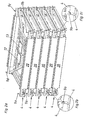
- FIG. 2a shows five stacked support structures 4, via the connecting elements 9a, 9b. 9c, 9d are interconnected.
- the Connecting elements 9c and 9d are visible only in the uppermost support structure 4, these are naturally also on all other four support structures 4 and the connection is made via these connecting elements 9a to 9d to the overlying support structure 4.
- the flexible planar structure is inserted in each case in the support structures 4.
- the connection and control devices 12 and at least one inverter 13 are located inside the folded support structures 4.
- FIG. 1b and Figure 2c show in detail the connecting elements 9a and 9b, as they are in communication with an overlying support structure 4 and fix them in position.
- FIG. 3a shows the bottom of a photovoltaic panel 3a or 3b, which are provided in this embodiment with two glued holding devices 14a and 14b.
- the holding devices 14a and 14b have in this embodiment, a stop element 15, with which the position of the photovoltaic panel 3a, 3b in the unfolded state on the carrier 10 (not shown) is specified.
- FIG. 4a shows a photovoltaic unit 2 in the folded state.
- two photovoltaic panels 3a and 3b are folded with their receiving surfaces to each other, they do not touch.
- sixteen of these photovoltaic panels 3a and 3b are arranged in pairs on the carrier 10.
- These photovoltaic panels 3a and 3b are fastened with holding devices 14a and 14b, which in turn can be fixed in their folded position via the locking device 16. Inserts also prevent contact of the photovoltaic panels (not shown).
- the holding devices 14a and 14b are connected to the locking device 17 and thus the photovoltaic panels 3a, 3b and fixed in position.
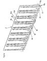
- FIG. 4b shows several folded photovoltaic units 2 space-saving juxtaposed.
- FIG. 5 the loading of a truck is shown, on which several support structures 4 as well as several photovoltaic units 2 place.
- the support structures 4 are stacked against each other slip-proof and the photovoltaic units 2 can be slipped by means of the carrier 10 on the back of the truck and mounted tilt-proof.
- up to six stationary photovoltaic systems can be transported simultaneously on a commercial truck.
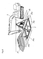
- FIG. 6a shows five stacked support structures 4, of which subsequently, as in FIG. 6b shown, a support structure 4 removed and these, as in FIG. 6c shown, can be placed at their destination. Subsequently, the uprights 5 and 6 are unfolded, whereby at the same time the flexible planar structure 20 unfolds and is tensioned. At the same time, together with the upright 6, the connection and control device 12 and the inverter 13 rise. The two uprights 5 and 6 are fixed in their erected position and can then receive the photovoltaic unit 2 (not shown).
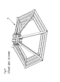
- Figure 7a shows an unfolded support structure 4.
- the bottom construction 7 was thereby folded over the joints 8a, 8b, 8c, 8d and forms a frame.
- the joints 8a, 8b, 8c, 8d can be fixed in position via the holes 18.
- the two uprights have 5 and 6 miterhoben automatically and are now also in position fixed by the holes 18, for example by screwing.
- the flexible planar structure 20 unfolded and thus has a larger base area 23 than the base surface 22 of the bottom structure 7 is.
- the base surface 22 of the floor structure 7 results from the surface which surrounds the frame
- the base 23 of the planar structure 20 results from the sum of the two tracks 24a and 24b of the sheet minus the area of a web where it covers the other track.
- the fact that the base 23 is larger than the base 22 allows a more stable anchoring of the support structure 4 in the ground.
- the two webs 24a, 24b of the flexible sheet-like structure 20 are laid in this embodiment by the struts of the floor construction 7, in fact threaded through (see FIG. 7b and FIG. 7c ), which leads to the automatic tensioning of the flexible sheet-like structure 20 when unfolding the floor structure 7.
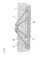
- the flexible sheet-like structure 20 is preferably designed to be permeable to water, whereby it is ensured in the rain, etc., that the water through the floor construction 4, in fact the flexible sheet-like structure 20, can run off and thus not adversely affect the stability of the floor structure 7 in the ground effect.
- the coupling elements 40 and 50 of the coupling device 41 are further arranged, which are provided for the pivoting of a photovoltaic unit, not shown (see FIG. 18a and 18b ).
- this support structure 4 can be operated as a "standalone system", provided that it is provided with a photovoltaic unit 2.
- the material of the flexible sheet-like structure 20 is designed tensile strength in the longitudinal and transverse directions. It has been shown that geosynthetics are best suited for these tasks of foundation. Likewise, of course, all other flexible materials for this foundation type are conceivable.
- FIG. 9 shows FIG. 9 another, different support structure 4 for this foundation type.
- a support structure 4 can also be a two-dimensional formed 20 are introduced and just in FIG. 8 stated foundation method.
- FIG. 10 shows a further variant of a possible anchoring method of a support structure 4 for a photovoltaic unit 2 of a stationary photovoltaic system 1 (not shown).
- first soil material 21 is excavated and thereby an excavation 25 formed.
- the planar structure 20 is introduced into the excavation 25 and partially filled with soil material 21.
- This soil material is gravel in this embodiment, it could of course be used as any other material, as well as the excavation of the excavation 25th
- the floor construction 7 is applied to the excavation 25 on the partially filled planar structure 20.
- the ends of the sheet-like structure 20 are struck over the floor structure 7, thus contributing the soil material 21, which is located under the floor structure 7 as well to the secure anchoring of the floor construction 7 at.
- the excavation 25 is filled with soil material 21. Again, of course, any other material for filling the excavation 25 is conceivable.
- FIG. 11a shows five juxtaposed and folded photovoltaic units 2, which are located for example on a truck (not shown). From this one is taken now (as in FIG. 11b shown) and unfolded at their destination (as in FIG. 11c shown).
- FIG. 11d shows an unfolded photovoltaic unit 2, consisting of sixteen photovoltaic panels 3a and 3b (for clarity, only six of the sixteen panels were marked).
- the panels 3a, 3b are pivotally attached to the carrier 10 via holding devices 14a and 14b. By swinging the photovoltaic panels 3a, 3b, these are automatically brought into the correct position, since the holding devices 14a and 14b have a stop element 15 (not shown).
- the holding devices 14a and 14b and with them the photovoltaic panels 3a and 3b which are preferably connected by adhesive bonding, can be fixed in their position by means of the locking device 17.
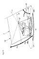
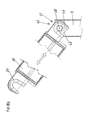
- FIG. 12 shows a photovoltaic system 1, which has a photovoltaic unit 2 and a support structure 4. Furthermore, a support member 30, a drive device 31, and a 3D spherical plain bearing 34 are disposed between the photovoltaic unit 2 and the support structure 4, which serve to displace the photovoltaic unit 2 to follow the state of the sun.
- the connection and control device 12 and the inverter 13 is arranged on the uprights 6, the connection and control device 12 and the inverter 13 is arranged.
- this photovoltaic system 1 can serve as a "stand-alone photovoltaic power plant”.
- the 3D spherical plain bearing 34 via which, among other things, the photovoltaic unit 2 is pivoted.
- the adjusting devices 32 and 42 (not shown) for the photovoltaic unit 2 result from the 3D spherical plain bearing 34 and the coupling elements 40 and 50 on the upright 5 and the coupling elements 39 and 49 on the support member 30 (not shown, see FIG. 18a and FIG. 18b ).
- the support structure 4 is first set up and unfolded when installing the photovoltaic system 1. Subsequently, the support structure 4 is aligned and anchored in the ground. Thereafter, the 3D spherical plain bearing 34 is mounted on the upright 6. Now, the photovoltaic unit 2 can be mounted on the support structure 4 and attached to the support member 30 and the 3D spherical plain bearing 34. Subsequently, the drive device 31 can be connected to the carrier 10 of the photovoltaic unit 2.
- the drive device 31 is equipped with a drive 33, which has a piston-cylinder unit 44 in this embodiment. With this, preferably one, drive device 31, both the uniaxial adjustment device 32 and the uniaxial adjustment device 42 can be actuated.
- the bottom structure 7 of the support structure 4 here has a flexible planar structure 20, with which the photovoltaic system 1 can be anchored in the ground.
- the photovoltaic unit 2 consists in this embodiment of eight photovoltaic panels 3a and eight photovoltaic panels 3b, which are arranged substantially symmetrically on a support 10 pivotally.
- the photovoltaic panels 3a and 3b have holding devices 14a and 14b, via which the photovoltaic panels 3a and 3b on the carrier 10 can be pivoted. By the locking devices 17, the photovoltaic panels 3a, 3b can be fixed in its unfolded position.
- FIG. 13a shows the schematic representation of a photovoltaic system 1 of a photovoltaic unit 2 on a support structure. 4
- the photovoltaic unit 2 has its ideal angle of inclination.
- the angle of inclination is referred to as elevation h in the photovoltaic technique, ie it is the angle formed by the receiving surface of the photovoltaic unit 2 with the horizontal plane. This results from the different heights of the two posts 5 and 6 and the distance between the two posts 5, 6 to each other.
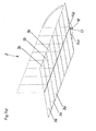
- the adjusting axis V 1 of the adjusting device 32 extends substantially in the plane of the photovoltaic unit 2. This deviates from the imaginary center line M of the photovoltaic unit 2 and forms an angle ⁇ 1 to it .
- the projection of the adjustment axis V 1 on the horizontal plane forms the projected adjustment axis P 1 .
- the projection of the surface normal of the photovoltaic unit 2 onto the horizontal plane yields the projected surface normal n '.
- the extension of the projected surface normal n ' forms the Einrichtachse E when the photovoltaic unit 2 in the Einrichtposition 35, as shown here, is located.
- the projected adjustment axis P 1 forms an angle EP 1 to the setup axis E.
- the angle EP 1 is thus the angle ⁇ 1 projected onto the horizontal plane 1 .
- the adjusting axis V 2 of the adjusting device 42 extends substantially in the plane of the photovoltaic unit 2. This deviates from the imaginary center axis M in the photovoltaic unit 2 and forms an angle ⁇ 2 to it .
- the projection of the adjustment axis V 2 on the horizontal plane forms the projected adjustment axis P 2 .
- the projection of the surface normal of the photovoltaic unit 2 onto the horizontal plane yields the projected surface normal n '.
- the extension of the projected surface normal n ' forms the setup axis E.
- the projected adjustment axis P 2 forms an angle EP 2 to the setup axis E.
- the angle EP 2 is thus the angle ⁇ 2 projected onto the horizontal plane 1.
- the elevation h min in the set-up position 35 is approximately 20 °.
- the angle ⁇ 1 or ⁇ 2 is selected in practice between 20 ° and 30 °, in a preferred embodiment, the angle ⁇ 1 or ⁇ 2 is about 24 °. This value depends on the dimensions of the photovoltaic system 1 and can therefore vary widely. These values were determined in model experiments, as well as their calculation would of course be possible.
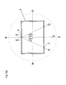
- FIG. 13b shows the top view of the support structure 4 of a photovoltaic system 1 (not shown).
- the support structure 4 was shown only schematically.
- the photovoltaic unit 2 was not shown in this figure, as well as the setup position 35 and the two adjusting devices 32 and 42:
- the installation of the support structure 4 is usually carried out so that the orientation of the support structure 4 is selected so that the Einrichtachse E thereby has a substantially north-south course.
- the Einrichtachse E is formed by the projection of the surface normal n of the photovoltaic unit 2 to the horizontal plane (in the Einrichtposition 35 of the photovoltaic unit 2, which occurs when the photovoltaic unit 2 has an ideal elevation h min ).
- This setup position 35 occurs in this embodiment, when the photovoltaic unit 2 rests in both adjusting devices 32 and 42.
- the front edge of Photovoltaic unit 2 is formed substantially normal to the south direction and extends substantially parallel to the horizontal plane.
- the projection of the adjustment axis V 2 on the horizontal plane forms the projected adjustment axis P 2 .
- This projected adjustment axis P 2 is located in the same plane as the Einrichtachse E and it runs neither in the Einrichtachse E nor parallel to it, it cuts the Einrichtachse E and forms with it an angle EP 2 , which in a preferred embodiment between 20 ° and 30 °, lies.
- the two adjustment axes V 1 and V 2 are in a preferred embodiment substantially in a plane, preferably substantially in or parallel to the plane of the receiving surface of the photovoltaic unit 2. This causes the pivoting about the two adjustment axes V 1 and V 2 is symmetrical to setup position 35 and thus symmetrical to Einrichtachse E.
- Figure 14a shows the pivoting about the adjustment axis V 1 of the adjusting device 32.
- the pivoting of the photovoltaic unit 2 was carried out starting from the Einrichtposition 35, where the photovoltaic unit 2 has an ideal elevation h min ( FIG. 14b ). After the maximum pivoting, the photovoltaic unit 2 has the end position 36 with maximum elevation h max .
- the side edge 45 of the photovoltaic unit 2 is in the end position 36 substantially parallel to the horizontal plane.
- the value of the angle EP 1 depends inter alia on the following factors: The size and shape of the photovoltaic unit 2, the distance between the pivot points on the adjustment axis V 1 from the ground and how far the pivot points of the adjustment axis V 1 from the edges 45 of the photovoltaic unit 2 and the center are spaced.
- the second pivot point on the adjustment axis V 1 is closer to the center (best in the region of the center) on the arranged opposite the uprights 5 uprights 6, whereby the effect comes about that the pivoting of the photovoltaic unit 2 via the pivot point on the uprights 5 causes a smaller Verschwenkweg the photovoltaic unit 2 relative to the ground and the pivoting of the photovoltaic unit 2 via causes the pivot point on the uprights 6 a larger Verschwenkweg, resulting in that the side edge 45 of the photovoltaic unit 2 performs different lengths paths in the direction of the ground.
- the projected adjustment axis P 1 would run in the Einrichtachse E and with the same design of the heights of the uprights 5 and 6, a pivoting of the photovoltaic unit 2 would this already at a lower pivoting in the front area Ground contact occur.
- either the shape of the photovoltaic unit 2 in the front area would have to be changed (reduced), which would lead to a lower power output - or the stands 5 and 6 would have to be made higher, which would be the photovoltaic Plant would be more susceptible to environmental impact (storm).
- a second adjustment axis V 2 is provided, which is preferably arranged in mirror image.
- the pivoting on the adjustment axis V 2 is analogous to the same as described in the adjustment axis V 1 and with the same effect analogously.
- FIG. 15 shows the schematic representation of a photovoltaic system 1 with a photovoltaic unit 2 and a support structure 4.
- the photovoltaic system 1 has two adjustment devices 32 and 42, via which the photovoltaic unit 2 can be tilted.
- the adjustment axis V 1 is formed.
- the adjustment axis V 2 is formed.
- These adjustment axes V 1 and V 2 each form an angle ⁇ 1 , ⁇ 2 to an imaginary center axis M of the photovoltaic unit 2.
- the photovoltaic unit 2 is in this embodiment in its set-up position 35, which is given when the photovoltaic Unit 2 which has an ideal elevation h min with respect to the sun.
- a pivoting of the photovoltaic unit 2 via the adjustment axis V 1 causes, as shown in this example, a pivoting of the photovoltaic unit 2 to the west (see FIG. 16 ).
- a pivoting about the adjustment axis V 2 causes a pivoting of the photovoltaic unit 2 to the east (see FIG. 17 ).
- FIG. 18a shows the support member 30, which has attachment points for the preferably flat design photovoltaic unit 2 (not shown).
- a part of the adjusting device 32, which is located on the uprights 5, here has a coupling element 40 of the coupling device 41.
- the support member 30 has a coupling element 39 of the coupling device 41.
- the two coupling elements 39 and 40 are in this case a connection and are locked by the locking device 43 and thus can not be separated. However, they can be rotated relative to one another, thus pivoting can take place via the adjusting device 32 and via the two coupling elements 39 and 40.
- the coupling element 49 is arranged, which is not coupled with the coupling element 50 of the post 5 at this time (not shown).
- FIG. 18b the adjustment for the adjusting device 42 is shown, wherein the two coupling elements 49 and 50 of the coupling device 41 are in communication and have been locked by the locking device 43.
- the coupling element 39 is arranged, it can be seen that at this time, the locking device 43 does not project into the region of the coupling element 39.
- the locking by the locking device 43 always takes place only on one side of the support part, that is, it can always be done only by pivoting about the adjusting device 32 or via the adjusting device 42.
- FIGS. 19a to 19c shows a 3D spherical plain bearing over which the carrier 10 and thus the photovoltaic unit 2 (not shown) by means of the adjusting devices 32 and 42 can be pivoted.
- This three-dimensionally pivotable, maintenance-free bearing is used for the positive reception of the carrier 10, which is tracked as a support part of the photovoltaic unit 2 in accordance with the Clarvierbahn in different positions.
- the bearing 34 is made of hot-dip galvanized, welded and bolted steel parts and is guided by sintered bronze bushings and POM plastics in conjunction with stainless steel bolts.
- At the first axis of rotation of the carrier 10 is positively received by four bearing shells of POM and rotatably mounted. The occurring axial forces are absorbed by a flange welded to the carrier 10 and between carrier 10 and bearing 34 arranged POM discs.
- the 3D spherical plain bearing 34 is in two parts and is screwed for mounting on the carrier 10 and inserted the bearing shells. At the second axis of rotation, the pivoting movement takes place via two flange bushes made of sintered bronze. The flanged bushes are pressed into the welded-on bearing blocks and the 3D spherical plain bearing 34 is received by stainless steel bolts and washers with sufficient axial play.
Landscapes
- Engineering & Computer Science (AREA)
- Life Sciences & Earth Sciences (AREA)
- Sustainable Development (AREA)
- Physics & Mathematics (AREA)
- Sustainable Energy (AREA)
- Thermal Sciences (AREA)
- Chemical & Material Sciences (AREA)
- Combustion & Propulsion (AREA)
- Mechanical Engineering (AREA)
- General Engineering & Computer Science (AREA)
- Photovoltaic Devices (AREA)
Claims (15)
- Construction support (4) pour une installation photovoltaïque stationnaire (1), comportant :- une partie support (30) qui présente des zones de fixation pour une unité photovoltaïque (2) conçue plane,- au moins un dispositif d'entraînement (31) pour le réglage motorisé de la partie support (30),- au moins un dispositif de réglage uniaxe (32) qui permet de régler une unité photovoltaïque (2) fixée à la partie support (30) en azimut (a) et élévation (h) autour d'un axe de réglage (V1) entre une position de mise au point (35) et une position finale (36), dans laquelle la projection de la normale de surface (n) de l'unité photovoltaïque (2) sur le plan horizontal dans la position de mise au point (35) définit un axe de mise au point (E) et la projection de l'axe de réglage (V1) sur le plan horizontal définit un axe de réglage (P1) projeté,caractérisée en ce que l'axe de réglage (P1) projeté forme par rapport à l'axe de mise au point (E) un angle (EP1) dans une plage supérieure à 5 degrés et inférieure à 80 degrés, de préférence dans une plage supérieure à 10 degrés et inférieure à 60 degrés.
- Construction support selon la revendication 1, caractérisée en ce qu'il est prévu un deuxième dispositif de réglage uniaxe (42) qui est conçu de la même manière que le premier dispositif de réglage (32), dans laquelle la partie support (30) peut être couplée en alternance avec le premier dispositif de réglage (32) et avec le deuxième dispositif de réglage (42) et les plages de pivotement du premier dispositif de réglage (32) et du deuxième dispositif de réglage (42) sont disposées en miroir par rapport à l'axe de mise au point (E).
- Construction support selon la revendication 2, caractérisée en ce que le dispositif d'entraînement (31) comprend un entraînement commun (33) pour les deux dispositifs de réglage (32, 42).
- Construction support selon la revendication 3, caractérisée en ce que l'entraînement (33) du dispositif d'entraînement (31) est conçu sous forme d'un entraînement linéaire.
- Construction support selon la revendication 4, caractérisée en ce que l'entraînement linéaire du dispositif d'entraînement (31) comprend au moins une unité de vérin à piston (44).
- Construction support selon l'une quelconque des revendications 1 à 5, caractérisée en ce que la construction support (4) comprend au moins une articulation 3D, de préférence une articulation à rotule 3D (34), pour le réglage de la partie support (30).
- Construction support selon l'une quelconque des revendications 2 à 6, caractérisée en ce que la construction support (4) comprend un dispositif de couplage (41) équipé d'éléments de couplage (39, 40, 49, 50) correspondants qui permettent de coupler les deux dispositifs de réglage (32, 42) en alternance avec la partie support (30).
- Construction support selon la revendication 7, caractérisée en ce que la construction support (4) comprend un dispositif de verrouillage (43) qui permet de verrouiller et de déverrouiller en alternance les éléments de couplage (39, 40, 49, 50) correspondants respectifs du dispositif de couplage (41).
- Construction support selon la revendication 8, caractérisée en ce que le dispositif de verrouillage (43) comprend un entraînement, de préférence un entraînement linéaire, qui permet de verrouiller et de déverrouiller en alternance les éléments de couplage (39, 40, 49, 50) correspondants respectifs du dispositif de couplage (41).
- Construction support selon l'une quelconque des revendications précédentes 7 à 9, caractérisé en ce qu'un pivotement de la partie support (30) par le biais du premier dispositif de réglage (32) provoque un soulèvement de la partie support (30) d'au moins un élément de couplage (50) du deuxième dispositif de réglage (42) et un pivotement de la partie support (30) par le biais du deuxième dispositif de réglage (42) provoque un soulèvement de la partie support (30) d'au moins un élément de couplage (40) du premier dispositif de réglage (32).
- Construction support selon l'une quelconque des revendications 7 à 10, dans laquelle la construction support (4) comprend :- au moins deux montants (5, 6) - de préférence de longueur différente - sur lesquels sont disposés les deux dispositifs de réglage (32, 42), l'articulation 3D et au moins deux éléments de couplage (40, 50) du dispositif de couplage (41),- un dispositif de branchement et de commande (12),caractérisée en ce qu'au moins deux éléments de couplage (40, 50) du dispositif de couplage (41) sont disposés sur un montant (5) et/ou le dispositif de branchement et de commande (12) et/ou l'articulation 3D sont disposés sur l'autre montant (6) et/ou un montant (6) présente une forme essentiellement triangulaire et/ou un montant (5) présente une forme essentiellement de quadrilatère et/ou au moins un montant (5, 6), de préférence les deux, présente au moins un entretoisement.
- Construction support selon l'une quelconque des revendications 1 à 11, caractérisée en ce que ladite au moins une zone au niveau de laquelle le dispositif d'entraînement (31) entraîne la partie support (30) est distante d'une zone, de préférence de toutes les zones, au niveau desquelles le dispositif de réglage (32, 42) règle la partie support (30).
- Construction support (4) selon l'une quelconque des revendications 1 à 12, dans laquelle la construction support (4) comprend des zones de fixation destinées à la fixation de l'unité photovoltaïque (2), caractérisée en ce que la construction support (4) peut être assemblée à plat.
- Construction support (4) selon l'une quelconque des revendications 1 à 13, comprenant :- une construction de sol (7) qui peut être enfouie en partie dans le sol,- une structure plane (20) pouvant être enfouie dans le sol qui, à l'état monté, est connectée à la construction de sol (7) de sorte que les forces agissantes sur la structure plane (20) par la charge du matériau du sol (21) peuvent être transmises sur la construction de sol (7) pour l'ancrage sûr de la construction de sol (7) dans le sol, caractérisée en ce que la structure plane (20) est conçue flexible.
- Installation photovoltaïque stationnaire (1) équipée d'une construction support (4) selon l'une quelconque des revendications 1 à 14.
Applications Claiming Priority (2)
| Application Number | Priority Date | Filing Date | Title |
|---|---|---|---|
| AT0182309A AT509124A1 (de) | 2009-11-18 | 2009-11-18 | Verstelleinrichtung einer stationären photovoltaik-anlage |
| PCT/AT2010/000441 WO2011060467A1 (fr) | 2009-11-18 | 2010-11-16 | Dispositif de réglage d'une installation photovoltaïque stationnaire |
Publications (2)
| Publication Number | Publication Date |
|---|---|
| EP2502009A1 EP2502009A1 (fr) | 2012-09-26 |
| EP2502009B1 true EP2502009B1 (fr) | 2014-07-02 |
Family
ID=43759644
Family Applications (1)
| Application Number | Title | Priority Date | Filing Date |
|---|---|---|---|
| EP10787670.8A Not-in-force EP2502009B1 (fr) | 2009-11-18 | 2010-11-16 | Dispositif de réglage d'une installation photovoltaïque stationnaire |
Country Status (6)
| Country | Link |
|---|---|
| EP (1) | EP2502009B1 (fr) |
| CN (1) | CN102612628A (fr) |
| AT (1) | AT509124A1 (fr) |
| CA (1) | CA2780924A1 (fr) |
| EA (1) | EA201290348A1 (fr) |
| WO (1) | WO2011060467A1 (fr) |
Families Citing this family (4)
| Publication number | Priority date | Publication date | Assignee | Title |
|---|---|---|---|---|
| KR101391273B1 (ko) * | 2009-12-31 | 2014-05-07 | 생―고뱅 퍼포먼스 플라스틱스 팜푸스 게엠베하 | 재생 가능 에너지원으로부터 전력을 발생시키기 위한 발전 구조물 |
| CN103441185B (zh) * | 2013-08-08 | 2016-07-13 | 中山大学 | 一种在东西向斜坡上安装光伏阵列的方法及装置 |
| MD1052Z (ro) * | 2015-11-16 | 2017-02-28 | Технический университет Молдовы | Sistem de orientare biaxială a unui panou fotovoltaic |
| EP3764539B1 (fr) * | 2018-03-05 | 2022-11-02 | Sumitomo Electric Industries, Ltd. | Procédé de fabrication de module photovoltaïque à concentrateur, et gabarit de support |
Family Cites Families (6)
| Publication number | Priority date | Publication date | Assignee | Title |
|---|---|---|---|---|
| GB1600705A (en) * | 1977-05-19 | 1981-10-21 | Guernsey Gas Light | Solar tracking device |
| US4245153A (en) * | 1979-03-09 | 1981-01-13 | Porter David R | Sun tracking system for solar collector |
| DE3706348A1 (de) * | 1987-02-27 | 1988-09-08 | Bomin Solar Gmbh & Co Kg | Sonnenkonzentrationsspiegel |
| US6563040B2 (en) * | 2001-10-11 | 2003-05-13 | Pinnacle West Capital Corporation | Structure for supporting a photovoltaic module in a solar energy collection system |
| DE102006022982B4 (de) * | 2006-04-12 | 2014-09-04 | Georg Kredler | Vorrichtung zur Montierung wenigstens eines Solarmoduls zur wenigstens einachsigen Nachführung |
| DE202007017719U1 (de) * | 2007-12-17 | 2008-03-06 | Pietrzak, Arnd | System zum Unterstützen der Energiegewinnung aus Sonnenstrahlung |
-
2009
- 2009-11-18 AT AT0182309A patent/AT509124A1/de not_active Application Discontinuation
-
2010
- 2010-11-16 EP EP10787670.8A patent/EP2502009B1/fr not_active Not-in-force
- 2010-11-16 WO PCT/AT2010/000441 patent/WO2011060467A1/fr not_active Ceased
- 2010-11-16 CN CN2010800521691A patent/CN102612628A/zh active Pending
- 2010-11-16 CA CA2780924A patent/CA2780924A1/fr not_active Abandoned
- 2010-11-16 EA EA201290348A patent/EA201290348A1/ru unknown
Also Published As
| Publication number | Publication date |
|---|---|
| AT509124A1 (de) | 2011-06-15 |
| EA201290348A1 (ru) | 2012-12-28 |
| WO2011060467A1 (fr) | 2011-05-26 |
| EP2502009A1 (fr) | 2012-09-26 |
| CA2780924A1 (fr) | 2011-05-26 |
| CN102612628A (zh) | 2012-07-25 |
Similar Documents
| Publication | Publication Date | Title |
|---|---|---|
| EP2843322B1 (fr) | Dispositif de support et de suivi de la position du soleil d'unités de poursuite pour panneaux solaires | |
| EP2737143B1 (fr) | Dispositif d'ancrage de superstructures dans le sol | |
| EP4277120B1 (fr) | Installation photovoltaïque | |
| WO2012152344A2 (fr) | Dispositif d'orientation et/ou suiveur pour capteurs solaires | |
| EP2425072A2 (fr) | Abri | |
| AT512937B1 (de) | Tragvorrichtung für Solarpanele | |
| EP3853995A1 (fr) | Élément mural | |
| DE102006022982B4 (de) | Vorrichtung zur Montierung wenigstens eines Solarmoduls zur wenigstens einachsigen Nachführung | |
| WO2011060467A1 (fr) | Dispositif de réglage d'une installation photovoltaïque stationnaire | |
| EP1601022A1 (fr) | Installation solaire | |
| EP2502282A2 (fr) | Construction de base d'un dispositif photovoltaïque stationnaire | |
| EP4186159B1 (fr) | Structure de support destinée à supporter des modules solaires et des éléments de plafond | |
| WO2013075257A2 (fr) | Installation solaire à poursuite à un ou deux axes | |
| DE202008015767U1 (de) | Nachführungseinrichtung für plattenförmige Solarmodule | |
| WO2011060471A2 (fr) | Installation photovoltaïque stationnaire | |
| WO2016202941A2 (fr) | Dispositif solaire | |
| AT525626B1 (de) | Mobile Containerraumvorrichtung | |
| DE202008010427U1 (de) | Solarkollektoranordnung | |
| DE102009022876A1 (de) | Nachführeinheit sowie Sonnenkollektor- oder Photovoltaikeinheit | |
| DE102018131953B4 (de) | Drehlagerbare Wohneinheit und Verfahren zum Anordnen der Wohneinheit in einer flächenoptimierten Drehposition sowie Verwendung | |
| AT526639B1 (de) | Schutzsystem | |
| DE202019000595U1 (de) | Überdachung für Baukörper | |
| DE202010003802U1 (de) | Solaranlagenhalle | |
| DE3500694A1 (de) | Solarkraftwerk | |
| DE202023104438U1 (de) | Mobiles Verkehrszeichensystem |
Legal Events
| Date | Code | Title | Description |
|---|---|---|---|
| PUAI | Public reference made under article 153(3) epc to a published international application that has entered the european phase |
Free format text: ORIGINAL CODE: 0009012 |
|
| 17P | Request for examination filed |
Effective date: 20120605 |
|
| AK | Designated contracting states |
Kind code of ref document: A1 Designated state(s): AL AT BE BG CH CY CZ DE DK EE ES FI FR GB GR HR HU IE IS IT LI LT LU LV MC MK MT NL NO PL PT RO RS SE SI SK SM TR |
|
| DAX | Request for extension of the european patent (deleted) | ||
| GRAP | Despatch of communication of intention to grant a patent |
Free format text: ORIGINAL CODE: EPIDOSNIGR1 |
|
| INTG | Intention to grant announced |
Effective date: 20130814 |
|
| GRAS | Grant fee paid |
Free format text: ORIGINAL CODE: EPIDOSNIGR3 |
|
| GRAA | (expected) grant |
Free format text: ORIGINAL CODE: 0009210 |
|
| AK | Designated contracting states |
Kind code of ref document: B1 Designated state(s): AL AT BE BG CH CY CZ DE DK EE ES FI FR GB GR HR HU IE IS IT LI LT LU LV MC MK MT NL NO PL PT RO RS SE SI SK SM TR |
|
| REG | Reference to a national code |
Ref country code: GB Ref legal event code: FG4D Free format text: NOT ENGLISH |
|
| REG | Reference to a national code |
Ref country code: CH Ref legal event code: EP Ref country code: AT Ref legal event code: REF Ref document number: 676141 Country of ref document: AT Kind code of ref document: T Effective date: 20140715 |
|
| REG | Reference to a national code |
Ref country code: IE Ref legal event code: FG4D Free format text: LANGUAGE OF EP DOCUMENT: GERMAN |
|
| REG | Reference to a national code |
Ref country code: DE Ref legal event code: R096 Ref document number: 502010007400 Country of ref document: DE Effective date: 20140814 |
|
| REG | Reference to a national code |
Ref country code: NL Ref legal event code: VDEP Effective date: 20140702 |
|
| REG | Reference to a national code |
Ref country code: LT Ref legal event code: MG4D |
|
| PG25 | Lapsed in a contracting state [announced via postgrant information from national office to epo] |
Ref country code: NO Free format text: LAPSE BECAUSE OF FAILURE TO SUBMIT A TRANSLATION OF THE DESCRIPTION OR TO PAY THE FEE WITHIN THE PRESCRIBED TIME-LIMIT Effective date: 20141002 Ref country code: LT Free format text: LAPSE BECAUSE OF FAILURE TO SUBMIT A TRANSLATION OF THE DESCRIPTION OR TO PAY THE FEE WITHIN THE PRESCRIBED TIME-LIMIT Effective date: 20140702 Ref country code: BG Free format text: LAPSE BECAUSE OF FAILURE TO SUBMIT A TRANSLATION OF THE DESCRIPTION OR TO PAY THE FEE WITHIN THE PRESCRIBED TIME-LIMIT Effective date: 20141002 Ref country code: GR Free format text: LAPSE BECAUSE OF FAILURE TO SUBMIT A TRANSLATION OF THE DESCRIPTION OR TO PAY THE FEE WITHIN THE PRESCRIBED TIME-LIMIT Effective date: 20141003 Ref country code: SE Free format text: LAPSE BECAUSE OF FAILURE TO SUBMIT A TRANSLATION OF THE DESCRIPTION OR TO PAY THE FEE WITHIN THE PRESCRIBED TIME-LIMIT Effective date: 20140702 Ref country code: CZ Free format text: LAPSE BECAUSE OF FAILURE TO SUBMIT A TRANSLATION OF THE DESCRIPTION OR TO PAY THE FEE WITHIN THE PRESCRIBED TIME-LIMIT Effective date: 20140702 Ref country code: ES Free format text: LAPSE BECAUSE OF FAILURE TO SUBMIT A TRANSLATION OF THE DESCRIPTION OR TO PAY THE FEE WITHIN THE PRESCRIBED TIME-LIMIT Effective date: 20140702 Ref country code: FI Free format text: LAPSE BECAUSE OF FAILURE TO SUBMIT A TRANSLATION OF THE DESCRIPTION OR TO PAY THE FEE WITHIN THE PRESCRIBED TIME-LIMIT Effective date: 20140702 Ref country code: PT Free format text: LAPSE BECAUSE OF FAILURE TO SUBMIT A TRANSLATION OF THE DESCRIPTION OR TO PAY THE FEE WITHIN THE PRESCRIBED TIME-LIMIT Effective date: 20141103 |
|
| PG25 | Lapsed in a contracting state [announced via postgrant information from national office to epo] |
Ref country code: CY Free format text: LAPSE BECAUSE OF FAILURE TO SUBMIT A TRANSLATION OF THE DESCRIPTION OR TO PAY THE FEE WITHIN THE PRESCRIBED TIME-LIMIT Effective date: 20140702 Ref country code: HR Free format text: LAPSE BECAUSE OF FAILURE TO SUBMIT A TRANSLATION OF THE DESCRIPTION OR TO PAY THE FEE WITHIN THE PRESCRIBED TIME-LIMIT Effective date: 20140702 Ref country code: RS Free format text: LAPSE BECAUSE OF FAILURE TO SUBMIT A TRANSLATION OF THE DESCRIPTION OR TO PAY THE FEE WITHIN THE PRESCRIBED TIME-LIMIT Effective date: 20140702 Ref country code: IS Free format text: LAPSE BECAUSE OF FAILURE TO SUBMIT A TRANSLATION OF THE DESCRIPTION OR TO PAY THE FEE WITHIN THE PRESCRIBED TIME-LIMIT Effective date: 20141102 Ref country code: PL Free format text: LAPSE BECAUSE OF FAILURE TO SUBMIT A TRANSLATION OF THE DESCRIPTION OR TO PAY THE FEE WITHIN THE PRESCRIBED TIME-LIMIT Effective date: 20140702 Ref country code: LV Free format text: LAPSE BECAUSE OF FAILURE TO SUBMIT A TRANSLATION OF THE DESCRIPTION OR TO PAY THE FEE WITHIN THE PRESCRIBED TIME-LIMIT Effective date: 20140702 Ref country code: NL Free format text: LAPSE BECAUSE OF FAILURE TO SUBMIT A TRANSLATION OF THE DESCRIPTION OR TO PAY THE FEE WITHIN THE PRESCRIBED TIME-LIMIT Effective date: 20140702 |
|
| REG | Reference to a national code |
Ref country code: DE Ref legal event code: R097 Ref document number: 502010007400 Country of ref document: DE |
|
| PG25 | Lapsed in a contracting state [announced via postgrant information from national office to epo] |
Ref country code: EE Free format text: LAPSE BECAUSE OF FAILURE TO SUBMIT A TRANSLATION OF THE DESCRIPTION OR TO PAY THE FEE WITHIN THE PRESCRIBED TIME-LIMIT Effective date: 20140702 Ref country code: RO Free format text: LAPSE BECAUSE OF FAILURE TO SUBMIT A TRANSLATION OF THE DESCRIPTION OR TO PAY THE FEE WITHIN THE PRESCRIBED TIME-LIMIT Effective date: 20140702 Ref country code: IT Free format text: LAPSE BECAUSE OF FAILURE TO SUBMIT A TRANSLATION OF THE DESCRIPTION OR TO PAY THE FEE WITHIN THE PRESCRIBED TIME-LIMIT Effective date: 20140702 Ref country code: SK Free format text: LAPSE BECAUSE OF FAILURE TO SUBMIT A TRANSLATION OF THE DESCRIPTION OR TO PAY THE FEE WITHIN THE PRESCRIBED TIME-LIMIT Effective date: 20140702 Ref country code: DK Free format text: LAPSE BECAUSE OF FAILURE TO SUBMIT A TRANSLATION OF THE DESCRIPTION OR TO PAY THE FEE WITHIN THE PRESCRIBED TIME-LIMIT Effective date: 20140702 |
|
| PLBE | No opposition filed within time limit |
Free format text: ORIGINAL CODE: 0009261 |
|
| STAA | Information on the status of an ep patent application or granted ep patent |
Free format text: STATUS: NO OPPOSITION FILED WITHIN TIME LIMIT |
|
| 26N | No opposition filed |
Effective date: 20150407 |
|
| PG25 | Lapsed in a contracting state [announced via postgrant information from national office to epo] |
Ref country code: BE Free format text: LAPSE BECAUSE OF NON-PAYMENT OF DUE FEES Effective date: 20141130 Ref country code: MC Free format text: LAPSE BECAUSE OF FAILURE TO SUBMIT A TRANSLATION OF THE DESCRIPTION OR TO PAY THE FEE WITHIN THE PRESCRIBED TIME-LIMIT Effective date: 20140702 Ref country code: LU Free format text: LAPSE BECAUSE OF FAILURE TO SUBMIT A TRANSLATION OF THE DESCRIPTION OR TO PAY THE FEE WITHIN THE PRESCRIBED TIME-LIMIT Effective date: 20141116 |
|
| REG | Reference to a national code |
Ref country code: CH Ref legal event code: PL |
|
| GBPC | Gb: european patent ceased through non-payment of renewal fee |
Effective date: 20141116 |
|
| PG25 | Lapsed in a contracting state [announced via postgrant information from national office to epo] |
Ref country code: CH Free format text: LAPSE BECAUSE OF NON-PAYMENT OF DUE FEES Effective date: 20141130 Ref country code: LI Free format text: LAPSE BECAUSE OF NON-PAYMENT OF DUE FEES Effective date: 20141130 |
|
| REG | Reference to a national code |
Ref country code: IE Ref legal event code: MM4A |
|
| REG | Reference to a national code |
Ref country code: FR Ref legal event code: ST Effective date: 20150731 |
|
| PG25 | Lapsed in a contracting state [announced via postgrant information from national office to epo] |
Ref country code: IE Free format text: LAPSE BECAUSE OF NON-PAYMENT OF DUE FEES Effective date: 20141116 Ref country code: GB Free format text: LAPSE BECAUSE OF NON-PAYMENT OF DUE FEES Effective date: 20141116 |
|
| PG25 | Lapsed in a contracting state [announced via postgrant information from national office to epo] |
Ref country code: SI Free format text: LAPSE BECAUSE OF FAILURE TO SUBMIT A TRANSLATION OF THE DESCRIPTION OR TO PAY THE FEE WITHIN THE PRESCRIBED TIME-LIMIT Effective date: 20140702 Ref country code: FR Free format text: LAPSE BECAUSE OF NON-PAYMENT OF DUE FEES Effective date: 20141201 |
|
| PG25 | Lapsed in a contracting state [announced via postgrant information from national office to epo] |
Ref country code: SM Free format text: LAPSE BECAUSE OF FAILURE TO SUBMIT A TRANSLATION OF THE DESCRIPTION OR TO PAY THE FEE WITHIN THE PRESCRIBED TIME-LIMIT Effective date: 20140702 |
|
| PG25 | Lapsed in a contracting state [announced via postgrant information from national office to epo] |
Ref country code: TR Free format text: LAPSE BECAUSE OF FAILURE TO SUBMIT A TRANSLATION OF THE DESCRIPTION OR TO PAY THE FEE WITHIN THE PRESCRIBED TIME-LIMIT Effective date: 20140702 Ref country code: HU Free format text: LAPSE BECAUSE OF FAILURE TO SUBMIT A TRANSLATION OF THE DESCRIPTION OR TO PAY THE FEE WITHIN THE PRESCRIBED TIME-LIMIT; INVALID AB INITIO Effective date: 20101116 Ref country code: MT Free format text: LAPSE BECAUSE OF FAILURE TO SUBMIT A TRANSLATION OF THE DESCRIPTION OR TO PAY THE FEE WITHIN THE PRESCRIBED TIME-LIMIT Effective date: 20140702 |
|
| PGFP | Annual fee paid to national office [announced via postgrant information from national office to epo] |
Ref country code: DE Payment date: 20161128 Year of fee payment: 7 |
|
| REG | Reference to a national code |
Ref country code: DE Ref legal event code: R079 Ref document number: 502010007400 Country of ref document: DE Free format text: PREVIOUS MAIN CLASS: F24J0002540000 Ipc: F24S0030400000 |
|
| PGFP | Annual fee paid to national office [announced via postgrant information from national office to epo] |
Ref country code: AT Payment date: 20171130 Year of fee payment: 8 |
|
| REG | Reference to a national code |
Ref country code: DE Ref legal event code: R119 Ref document number: 502010007400 Country of ref document: DE |
|
| PG25 | Lapsed in a contracting state [announced via postgrant information from national office to epo] |
Ref country code: MK Free format text: LAPSE BECAUSE OF FAILURE TO SUBMIT A TRANSLATION OF THE DESCRIPTION OR TO PAY THE FEE WITHIN THE PRESCRIBED TIME-LIMIT Effective date: 20140702 |
|
| PG25 | Lapsed in a contracting state [announced via postgrant information from national office to epo] |
Ref country code: AL Free format text: LAPSE BECAUSE OF FAILURE TO SUBMIT A TRANSLATION OF THE DESCRIPTION OR TO PAY THE FEE WITHIN THE PRESCRIBED TIME-LIMIT Effective date: 20140702 Ref country code: DE Free format text: LAPSE BECAUSE OF NON-PAYMENT OF DUE FEES Effective date: 20180602 |
|
| REG | Reference to a national code |
Ref country code: AT Ref legal event code: MM01 Ref document number: 676141 Country of ref document: AT Kind code of ref document: T Effective date: 20181116 |
|
| PG25 | Lapsed in a contracting state [announced via postgrant information from national office to epo] |
Ref country code: AT Free format text: LAPSE BECAUSE OF NON-PAYMENT OF DUE FEES Effective date: 20181116 |