EP2502803A1 - Contrôleur pour appareil de direction assistée électrique - Google Patents
Contrôleur pour appareil de direction assistée électrique Download PDFInfo
- Publication number
- EP2502803A1 EP2502803A1 EP12156120A EP12156120A EP2502803A1 EP 2502803 A1 EP2502803 A1 EP 2502803A1 EP 12156120 A EP12156120 A EP 12156120A EP 12156120 A EP12156120 A EP 12156120A EP 2502803 A1 EP2502803 A1 EP 2502803A1
- Authority
- EP
- European Patent Office
- Prior art keywords
- mos
- fet
- fault
- steering apparatus
- power steering
- Prior art date
- Legal status (The legal status is an assumption and is not a legal conclusion. Google has not performed a legal analysis and makes no representation as to the accuracy of the status listed.)
- Granted
Links
Images

Classifications
-
- B—PERFORMING OPERATIONS; TRANSPORTING
- B62—LAND VEHICLES FOR TRAVELLING OTHERWISE THAN ON RAILS
- B62D—MOTOR VEHICLES; TRAILERS
- B62D5/00—Power-assisted or power-driven steering
- B62D5/04—Power-assisted or power-driven steering electrical, e.g. using an electric servo-motor connected to, or forming part of, the steering gear
- B62D5/0457—Power-assisted or power-driven steering electrical, e.g. using an electric servo-motor connected to, or forming part of, the steering gear characterised by control features of the drive means as such
- B62D5/0481—Power-assisted or power-driven steering electrical, e.g. using an electric servo-motor connected to, or forming part of, the steering gear characterised by control features of the drive means as such monitoring the steering system, e.g. failures
- B62D5/0487—Power-assisted or power-driven steering electrical, e.g. using an electric servo-motor connected to, or forming part of, the steering gear characterised by control features of the drive means as such monitoring the steering system, e.g. failures detecting motor faults
-
- B—PERFORMING OPERATIONS; TRANSPORTING
- B62—LAND VEHICLES FOR TRAVELLING OTHERWISE THAN ON RAILS
- B62D—MOTOR VEHICLES; TRAILERS
- B62D5/00—Power-assisted or power-driven steering
- B62D5/04—Power-assisted or power-driven steering electrical, e.g. using an electric servo-motor connected to, or forming part of, the steering gear
- B62D5/0457—Power-assisted or power-driven steering electrical, e.g. using an electric servo-motor connected to, or forming part of, the steering gear characterised by control features of the drive means as such
- B62D5/0481—Power-assisted or power-driven steering electrical, e.g. using an electric servo-motor connected to, or forming part of, the steering gear characterised by control features of the drive means as such monitoring the steering system, e.g. failures
-
- H—ELECTRICITY
- H02—GENERATION; CONVERSION OR DISTRIBUTION OF ELECTRIC POWER
- H02P—CONTROL OR REGULATION OF ELECTRIC MOTORS, ELECTRIC GENERATORS OR DYNAMO-ELECTRIC CONVERTERS; CONTROLLING TRANSFORMERS, REACTORS OR CHOKE COILS
- H02P29/00—Arrangements for regulating or controlling electric motors, appropriate for both AC and DC motors
- H02P29/02—Providing protection against overload without automatic interruption of supply
- H02P29/024—Detecting a fault condition, e.g. short circuit, locked rotor, open circuit or loss of load
- H02P29/0241—Detecting a fault condition, e.g. short circuit, locked rotor, open circuit or loss of load the fault being an overvoltage
-
- H—ELECTRICITY
- H03—ELECTRONIC CIRCUITRY
- H03K—PULSE TECHNIQUE
- H03K17/00—Electronic switching or gating, i.e. not by contact-making and –breaking
- H03K17/18—Modifications for indicating state of switch
-
- H—ELECTRICITY
- H03—ELECTRONIC CIRCUITRY
- H03K—PULSE TECHNIQUE
- H03K17/00—Electronic switching or gating, i.e. not by contact-making and –breaking
- H03K17/51—Electronic switching or gating, i.e. not by contact-making and –breaking characterised by the components used
- H03K17/56—Electronic switching or gating, i.e. not by contact-making and –breaking characterised by the components used by the use, as active elements, of semiconductor devices
- H03K17/687—Electronic switching or gating, i.e. not by contact-making and –breaking characterised by the components used by the use, as active elements, of semiconductor devices the devices being field-effect transistors
- H03K17/6871—Electronic switching or gating, i.e. not by contact-making and –breaking characterised by the components used by the use, as active elements, of semiconductor devices the devices being field-effect transistors the output circuit comprising more than one controlled field-effect transistor
- H03K17/6874—Electronic switching or gating, i.e. not by contact-making and –breaking characterised by the components used by the use, as active elements, of semiconductor devices the devices being field-effect transistors the output circuit comprising more than one controlled field-effect transistor in a symmetrical configuration
Definitions
- the present invention relates to a controller for an electrical power steering apparatus.
- a controller for a power steering as a prior art includes a MOS-FET as a switching element to turn on or off the conduct of the power.
- a parasitic diode is mounted at a reversed direction between a drain and a source of the MOS-FET, for example so that the current is flown in a direction from the drain to the source at a N-channel MOS-FET. According to this construction, the fault of the MOS-FET can not be detected because the current is flowing to continue its operation where the parasitic diode is on as a normal.
- one aspect of the present invention provides a controller for a power steering apparatus including a motor supplying a steering assist force to said power steering apparatus for a vehicle, a motor driving member outputting a driving power to the motor, a battery supplying power voltage to the motor driving member, an ignition switch turning on or off the battery, a switching member mounted in a conducting path from the battery to the motor driving member, and a condenser mounted at an input side of the motor driving member, the switching member has two switching elements to turn on or off the conducting path by turning on or off according to a driving signal being input into a gate, and parasitic diodes mounted in parallel between a drain and a source of the switching elements, the switching elements are connected in series at the opposite direction respectively on the conducting path and are connected to the ignition switch, wherein the controller comprises a voltage detecting member detecting output voltage from each of the switching elements; and a fault judging member judging faults of each of the switching elements and the parasitic diodes in accordance with each of the output
- the second aspect of the present invention provides a controller for a power steering apparatus wherein mainly the switching member turns on or off the switching elements in a predetermined sequence after the ignition switch is turned on. According to the second aspect, since it controls to turn on or off the two switching elements in the predetermined sequence, it can detect the faults of the switching elements certainly.
- the present invention therefore can detect the faults of the parasitic diodes even when the MOS-FET is used for the power relay, thereby providing the controller for the power steering apparatus to be able to detect the faults of the MOS-FET firmly.
- An electrical power steering apparatus 10 shown in Fig. 1 is a column assisted type electrical power steering apparatus including a motor 1, a reduction gear 2, a torque sensor 3, a speed sensor 4, a steering angle sensor 5 and a controller 6 (hereinafter referred as an ECU 6).
- a steering wheel 101 connected to one end of a steering shaft 102 as shown in Fig. 1 a rack shaft 104 is connected with the other end of the steering shaft 102 through a rack and pinion mechanism 103.
- rack shaft 104 is respectively connected with steered wheels 106 through a connecting member 105 having tie rods and knuckle arms.
- the steering shaft 102 is rotated to reciprocate the rack shaft 104 when a driver steers the steering wheel 101.
- a turning direction of the steered wheels 106 is changed in accordance with the reciprocating movement of the rack shaft 104.
- the electrical power steering apparatus 10 assists steering operation explained hereinafter in order to reduce load to the driver.
- the torque sensor 3 detects steering torque ⁇ acting to the steering shaft 102 by operation of the steering wheel 101.
- the speed sensor 4 detects vehicle speed V.
- the steering angle sensor 5 detects a rotational position of a rotor of the motor 1 (hereinafter referred as motor rotational angle ⁇ of the motor).
- the steering angle sensor 5 is constructed with, for example, a resolver.
- the ECU 6 receives power from a battery 100 to drive the motor 1 in accordance with the steering torque ⁇ , the vehicle speed V and the motor rotational angle ⁇ of the motor.
- the motor 1 is driven by the ECU 6 to generate steering assist force.
- the reduction gear 2 is located between the motor 1 and the steering shaft 102.
- the steering assist torque (hereinafter referred as assist force) generated by the motor 1 acts to rotate the steering shaft 102.
- the electrical power steering apparatus 10 acts as the steering assist by giving the assist force generated by the motor 1 to the steering mechanism of the vehicle.
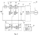
- Fig. 2 shows a circuit diagram of a control circuit included in the power steering apparatus 10.
- the control circuit shown in Fig. 2 includes power relays 13, 14, a condenser 18 and a motor driving circuit 11 (identified as “motor driving member” in the present invention).
- a power relay (identified as “switching member") is for example a MOS-FET includes each of switching elements and each of 1 st and 2 nd parasitic diodes 15, 16.
- the control circuit is mounted in the ECU 6 to be connected to the battery 100 through an ignition switch 17 (hereinafter referred as IG switch).
- IG switch ignition switch
- the motor driving circuit 11 is a well-known inverter consisting of three arm circuits connected in parallel respectively, each of which consists of two un-illustrated MOS-FET connected in series respectively.
- the motor driving circuit 11 consisting of six MOS-FETs as a switching element is inserted between two power lines L1, L2.
- the motor 1 is a three-phase blushless motor having a three-phase wire.
- the fault detecting circuit 12 outputs gate driving signals G1, G2 turning on or off the 1 st MOS-FET 13 and the 2 nd MOS-FET 14 and each of these gate driving signals G1, G2 is input into a gate terminal of each of the MOS-FETs.
- To the fault detecting circuit 12 are input both of an output from the 1 st MOS-FET 13 as a monitored voltage V1 divided by resistances 20, 21 in a power monitoring circuit 19 and of an output from the 2 nd MOS-FET 14 as a monitored voltage V2 divided by resistances 22, 23 in the power monitoring circuit 19 in accordance with the on and off stages of the 1 st MOS-FET 13 and the 2 nd MOS-FET 14.
- the monitored voltages V1, V2 being input into the fault detecting circuit 12 are respectively used for calculating process by the CPU mounted in the ECU 6 after being transformed by an A/D converter.
- the condenser 18 is mounted between two power lines L1 and L2 at an input side of the motor driving circuit 11.
- the condenser 18 accumulates charges from the battery 100 through an IG switch 17, the 1 st MOS-FET 13 and the 2 nd MOS-FET 14 and discharges the accumulated charges when amount of current flowing from the battery 100 to the motor driving circuit 11 is insufficient. Therefore, the condenser 18 acts as a condenser for absorbing current ripple.
- the fault detecting circuit 12 executes calculating process by a computer program that is operated by the CPU installed in the ECU 6 as shown in Fig. 2 .
- the CPU executes the ON/OFF control and the fault detecting of the 1 st MOS-FET 13 and the 2 nd MOS-FET 14 by detecting the above-identified amount of each stage in every predetermined sampling period and by executing each of next calculating processes predetermined periodically.
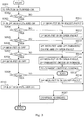
- Fig. 3 shows a flow of the operation by the ECU 6.
- the fault detecting circuit 12 judges whether the amount of the monitored voltage V1 of the output voltage from the 1 st MOS-FET 13 is under the predetermined reference value or not in Step S302 when the ignition (IG) switch 17 shown in Fig.2 is turned on in Step S301.
- the 1 st MOS-FET 13 and the 2 nd MOS-FET 14 are turned off because the gate driving signals G1, G2 are turned off.
- Step S311 where the amount of the monitored voltage V1 is over the predetermined reference value in NO at the Step S302, in other words the amount is in a high level showing the status that the 1 st MOS-FET 13 is abnormally connected by a short, it is judged in a fault of a short-circuit at the 1 st MOS-FET 13 in Step S311 to turn off the gate driving signals G1, G2, thereby the control by ECU 6 is ended in Step S317.
- Step S304 it is judged whether the amount of the monitored voltage V1 of the 1 st MOS-FET 13 is over a predetermined reference value or not.
- the amount of the monitored voltage V1 is under the last mentioned predetermined reference value Hi in NO at the Step S304, in other words the amount is in a low level showing the status that the 1 st MOS-FET 13 is abnormally unconnected by a open
- the amount of the monitored voltage V1 is over the predetermined reference value in YES at the Step S304, in other words the amount is in the high level, it is shifted to Step S305.
- Step S305 it is judged whether the amount of the monitored voltage V2 of the 2 nd MOS-FET 14 is over the predetermined reference value or not, same value to the predetermined reference value in Step S304. Where the amount of the monitored voltage V2 is under the predetermined reference value in NO at the Step S305, it is judged in a fault of an open-circuit at the 2 nd MOS-FET 14 and a fault of an open-circuit at the 2 nd parasitic diode 16 of the 2 nd MOS-FET 14 in Step S313 to turn off the gate driving signals G1, G2, thereby the control by ECU 6 is ended in Step S317.
- the amount of the monitored voltage V2 is over the predetermined reference value in YES at the Step S305, in other words the amount is in the high level, it is controlled to turn off the 1 st MOS-FET 13 by turning off the gate driving signal G1 in Step S306.
- Step S307 it is judged whether the amount of the monitored voltage V1 of the 1 st MOS-FET 13 is over the predetermined reference value or not.
- the amount of the monitored voltage V1 is under the predetermined reference value in NO at the Step S305, in other words in the low level, it is judged in a fault of an open-circuit at the 2 nd MOS-FET 14 and in a normal of a continuity state of the 2 nd parasitic diode 16 of the 2 nd MOS-FET 14 in Step S314, so that the ECU 6 changes to a current limiting control to limit the motor driving current under an allowable current value of the 2 nd parasitic diode 16 in the 2 nd MOS-FET 14 and continues its operation in Step S315.
- Step S309 it is judged whether the amount of the monitored voltage V1 of the 1 st MOS-FET 13 is under the predetermined reference value or not, same value to the predetermined reference value in Step S302. Where the amount of the monitored voltage V1 is over the predetermined reference value in NO at the Step S309, in other words in the high level, it is judged in a fault of an short-circuit at the 2 nd MOS-FET 14 in Step S316, thereby the ECU 6 turns off the gate driving signals G1, G2 to end its control in Step S317.
- the one embodiment of the electrical power steering apparatus 10 includes the 1 st MOS-FET 13 and the 2 nd MOS-FET 14 accommodating the 1 st parasitic diode 15 and the 2 nd parasitic diode 16 in the conducting path between the battery 100 and the motor driving circuit 11 and being connected in series at the opposite direction respectively, and the condenser 18 in an output side of the latter 2 nd MOS-FET 14.
- the ECU 6 of the controller of the electrical power steering apparatus controls to turn on or off the 1 st MOS-FET 13 and the 2 nd MOS-FET 14 in accordance with the predetermined sequence by turning on or off the gate driving signals G1, G2 to detect the fault of the 1 st MOS-FET 13, the 2 nd MOS-FET 14 and the 1 st parasitic diode 15 and the 2 nd parasitic diode 16 on the basis of the output voltage from each of the 1 st MOS-FET 13 and the 2 nd MOS-FET 14. It is therefore for the controller of the electrical power steering apparatus to be able to detect the fault of the MOS-FETs certainly and to judge the fault of the parasitic diode.
- the ECU 6 controls to limit the motor driving current so that the current of the source is under the allowable current for the parasitic diode.
- the ECU 6 can thereby maintain to control and prevent from making the 2 nd parasitic diode 16 overheat or fail based on continuing to flow the large current.
- the controller for the electrical power steering apparatus can achieve next effects.
- the controller of the prior art needs additional circuit accumulating a charge in another condenser to detect the short-fault or the open-fault of the MOS-FET consisting of the power relay, however the present invention does not need any additional detecting circuit by executing to detect the short-fault or the open-fault of the MOS-FET in the predetermined sequence.
- the invention is applied for the column assisted electrical power steering apparatus, however it may be applicable for a pinion assisted electrical power steering apparatus or a rack assisted electrical power steering apparatus.
- the electrical power steering apparatus 10 includes the 1 st MOS-FET 13 and the 2 nd MOS-FET 14 accommodating the 1 st parasitic diode 15 and the 2 nd parasitic diode 16 in the conducting path between the battery 100 and the motor driving circuit 11 and being connected in series at the opposite direction respectively, and the condenser 18 in an output side of the latter 2 nd MOS-FET 14.
- the ECU 6 of the controller of the electrical power steering apparatus controls to turn on or off the 1 st MOS-FET 13 and the 2 nd MOS-FET 14 in accordance with the predetermined sequence after the ignition switch 17 is turned on, detecting the fault of the 1 st MOS-FET 13, the 2 nd MOS-FET 14 and the 1 st parasitic diode 15 and the 2 nd parasitic diode 16 on the basis of the output voltage from each of the 1 st MOS-FET 13 and the 2 nd MOS-FET 14. It is therefore for the controller of the electrical power steering apparatus to be able to detect the fault of the MOS-FETs certainly and to judge the fault of the parasitic diode.
Landscapes
- Engineering & Computer Science (AREA)
- Chemical & Material Sciences (AREA)
- Combustion & Propulsion (AREA)
- Transportation (AREA)
- Mechanical Engineering (AREA)
- Power Engineering (AREA)
- Power Steering Mechanism (AREA)
- Steering Control In Accordance With Driving Conditions (AREA)
- Power Conversion In General (AREA)
Applications Claiming Priority (2)
| Application Number | Priority Date | Filing Date | Title |
|---|---|---|---|
| JP2011036764 | 2011-02-23 | ||
| JP2011066925A JP5742356B2 (ja) | 2011-02-23 | 2011-03-25 | 電動パワーステアリング装置の制御装置 |
Publications (2)
| Publication Number | Publication Date |
|---|---|
| EP2502803A1 true EP2502803A1 (fr) | 2012-09-26 |
| EP2502803B1 EP2502803B1 (fr) | 2014-07-02 |
Family
ID=45656145
Family Applications (1)
| Application Number | Title | Priority Date | Filing Date |
|---|---|---|---|
| EP12156120.3A Not-in-force EP2502803B1 (fr) | 2011-02-23 | 2012-02-20 | Contrôleur pour appareil de direction assistée électrique |
Country Status (3)
| Country | Link |
|---|---|
| US (1) | US8786228B2 (fr) |
| EP (1) | EP2502803B1 (fr) |
| JP (1) | JP5742356B2 (fr) |
Cited By (1)
| Publication number | Priority date | Publication date | Assignee | Title |
|---|---|---|---|---|
| CN103354415A (zh) * | 2013-06-28 | 2013-10-16 | 江苏浩峰汽车附件有限公司 | 一种用于防反接的n沟道mos管栅极悬浮驱动电路 |
Families Citing this family (18)
| Publication number | Priority date | Publication date | Assignee | Title |
|---|---|---|---|---|
| WO2014184888A1 (fr) | 2013-05-15 | 2014-11-20 | 三菱電機株式会社 | Dispositif de direction électrique |
| JP6111937B2 (ja) * | 2013-08-29 | 2017-04-12 | 株式会社デンソー | 電源遮断装置および電動機駆動装置 |
| JP6217248B2 (ja) * | 2013-08-30 | 2017-10-25 | 株式会社オートネットワーク技術研究所 | 半導体装置 |
| JP6418874B2 (ja) * | 2014-01-15 | 2018-11-07 | 株式会社マキタ | バッテリパック |
| KR20150134061A (ko) | 2014-05-21 | 2015-12-01 | 주식회사 만도 | 전자 제어 주행 안정 장치 및 그것의 모터 프리휠링 회로 고장 검출 방법 |
| KR102246702B1 (ko) * | 2015-02-05 | 2021-04-30 | 주식회사 만도 | 전동식 조향장치의 전자제어장치 및 그 전원제어방법 |
| US10371752B2 (en) * | 2015-04-23 | 2019-08-06 | Infineon Technologies Austria Ag | Switch device |
| JP6577270B2 (ja) | 2015-07-07 | 2019-09-18 | 株式会社東海理化電機製作所 | 故障診断回路、および故障診断方法 |
| JP6586800B2 (ja) * | 2015-07-08 | 2019-10-09 | 株式会社ジェイテクト | モータ制御装置 |
| JP2017210936A (ja) * | 2016-05-27 | 2017-11-30 | 日立オートモティブシステムズ株式会社 | 電磁負荷駆動回路の故障診断装置 |
| JP6561959B2 (ja) * | 2016-10-12 | 2019-08-21 | オンキヨー株式会社 | 電子機器 |
| JP7224100B2 (ja) * | 2017-02-27 | 2023-02-17 | 株式会社デンソー | 逆接続保護回路及び負荷システム |
| JP7171174B2 (ja) * | 2017-09-05 | 2022-11-15 | エドワーズ株式会社 | 真空ポンプ及びモータ制御装置 |
| JP6770986B2 (ja) | 2018-03-06 | 2020-10-21 | 日本電産モビリティ株式会社 | 誘導性負荷制御装置 |
| EP3798751A1 (fr) * | 2019-09-25 | 2021-03-31 | Leuze electronic GmbH + Co. KG | Système de sécurité |
| JP7259779B2 (ja) * | 2020-02-17 | 2023-04-18 | 株式会社デンソー | 過電流検出装置 |
| KR20230095314A (ko) | 2021-12-22 | 2023-06-29 | 주식회사 엘지에너지솔루션 | 배터리 보호 회로에서의 스위치 손상 진단 장치 및 방법, 그리고 이를 포함하는 배터리 관리 장치 |
| US12249826B2 (en) * | 2022-10-03 | 2025-03-11 | Nxp Usa, Inc. | Current limited power device |
Citations (5)
| Publication number | Priority date | Publication date | Assignee | Title |
|---|---|---|---|---|
| JP2008141612A (ja) | 2006-12-04 | 2008-06-19 | Denso Corp | 負荷駆動装置の故障検出装置および負荷駆動用ic |
| WO2010032705A1 (fr) * | 2008-09-17 | 2010-03-25 | 株式会社ジェイテクト | Contrôleur de moteur et dispositif de commande électrique de direction |
| EP2182629A2 (fr) * | 2008-11-04 | 2010-05-05 | Jtekt Corporation | Circuit de commande de moteur et appareil de direction assistée électrique |
| EP2226237A1 (fr) * | 2007-12-27 | 2010-09-08 | JTEKT Corporation | Dispositif de servodirection à entraînement électrique |
| JP2010252470A (ja) * | 2009-04-14 | 2010-11-04 | Jtekt Corp | モータ制御装置および電動パワーステアリング装置 |
Family Cites Families (1)
| Publication number | Priority date | Publication date | Assignee | Title |
|---|---|---|---|---|
| JP4930263B2 (ja) * | 2006-12-25 | 2012-05-16 | パナソニック株式会社 | 蓄電装置 |
-
2011
- 2011-03-25 JP JP2011066925A patent/JP5742356B2/ja not_active Expired - Fee Related
-
2012
- 2012-02-16 US US13/398,140 patent/US8786228B2/en active Active
- 2012-02-20 EP EP12156120.3A patent/EP2502803B1/fr not_active Not-in-force
Patent Citations (6)
| Publication number | Priority date | Publication date | Assignee | Title |
|---|---|---|---|---|
| JP2008141612A (ja) | 2006-12-04 | 2008-06-19 | Denso Corp | 負荷駆動装置の故障検出装置および負荷駆動用ic |
| EP2226237A1 (fr) * | 2007-12-27 | 2010-09-08 | JTEKT Corporation | Dispositif de servodirection à entraînement électrique |
| WO2010032705A1 (fr) * | 2008-09-17 | 2010-03-25 | 株式会社ジェイテクト | Contrôleur de moteur et dispositif de commande électrique de direction |
| EP2328268A1 (fr) * | 2008-09-17 | 2011-06-01 | JTEKT Corporation | Contrôleur de moteur et dispositif de commande électrique de direction |
| EP2182629A2 (fr) * | 2008-11-04 | 2010-05-05 | Jtekt Corporation | Circuit de commande de moteur et appareil de direction assistée électrique |
| JP2010252470A (ja) * | 2009-04-14 | 2010-11-04 | Jtekt Corp | モータ制御装置および電動パワーステアリング装置 |
Cited By (2)
| Publication number | Priority date | Publication date | Assignee | Title |
|---|---|---|---|---|
| CN103354415A (zh) * | 2013-06-28 | 2013-10-16 | 江苏浩峰汽车附件有限公司 | 一种用于防反接的n沟道mos管栅极悬浮驱动电路 |
| CN103354415B (zh) * | 2013-06-28 | 2016-01-20 | 江苏浩峰汽车附件有限公司 | 一种用于防反接的n沟道mos管栅极悬浮驱动电路 |
Also Published As
| Publication number | Publication date |
|---|---|
| US8786228B2 (en) | 2014-07-22 |
| EP2502803B1 (fr) | 2014-07-02 |
| US20120212159A1 (en) | 2012-08-23 |
| JP5742356B2 (ja) | 2015-07-01 |
| JP2012188101A (ja) | 2012-10-04 |
Similar Documents
| Publication | Publication Date | Title |
|---|---|---|
| EP2502803B1 (fr) | Contrôleur pour appareil de direction assistée électrique | |
| EP2301822B1 (fr) | Système de direction assistée électrique | |
| JP5157429B2 (ja) | 電動パワーステアリング装置 | |
| US11139679B2 (en) | Auxiliary power source device | |
| US8941337B2 (en) | Motor driving device and electric power steering apparatus including motor driving device | |
| US9762050B2 (en) | Motor drive device | |
| EP3193443B1 (fr) | Dispositif d'onduleur pour entraîner un moteur à courant alternatif polyphasé | |
| US8680808B2 (en) | Motor drive apparatus and electric power steering apparatus using the same | |
| US11283389B2 (en) | Motor system | |
| EP2328268A1 (fr) | Contrôleur de moteur et dispositif de commande électrique de direction | |
| EP1832885A1 (fr) | Dispositif de détection d'un défaut de mise à la terre pour circuit de commande de moteur | |
| US20160028336A1 (en) | Control apparatus for electric motor and control method for electric motor | |
| JP6111937B2 (ja) | 電源遮断装置および電動機駆動装置 | |
| JP2009035155A (ja) | 電動パワーステアリング装置 | |
| CN107585118B (zh) | 与外部装置共享电池的系统 | |
| US20140229066A1 (en) | Electronic control device for electric power steering apparatus | |
| US20200070874A1 (en) | Vehicle control apparatus | |
| CN103010293B (zh) | 电动助力转向系统 | |
| KR101721616B1 (ko) | 모터의 구동 제어 장치 및 방법 | |
| EP1720238A1 (fr) | Dispositif de prévention de l'adhérence d'un relais et dispositif d'entrainement par moteur | |
| JP5057026B2 (ja) | モータ駆動装置 | |
| JP6721214B2 (ja) | モータ制御装置 |
Legal Events
| Date | Code | Title | Description |
|---|---|---|---|
| PUAI | Public reference made under article 153(3) epc to a published international application that has entered the european phase |
Free format text: ORIGINAL CODE: 0009012 |
|
| AK | Designated contracting states |
Kind code of ref document: A1 Designated state(s): AL AT BE BG CH CY CZ DE DK EE ES FI FR GB GR HR HU IE IS IT LI LT LU LV MC MK MT NL NO PL PT RO RS SE SI SK SM TR |
|
| AX | Request for extension of the european patent |
Extension state: BA ME |
|
| 17P | Request for examination filed |
Effective date: 20130326 |
|
| 17Q | First examination report despatched |
Effective date: 20130930 |
|
| GRAP | Despatch of communication of intention to grant a patent |
Free format text: ORIGINAL CODE: EPIDOSNIGR1 |
|
| INTG | Intention to grant announced |
Effective date: 20140120 |
|
| GRAS | Grant fee paid |
Free format text: ORIGINAL CODE: EPIDOSNIGR3 |
|
| GRAA | (expected) grant |
Free format text: ORIGINAL CODE: 0009210 |
|
| AK | Designated contracting states |
Kind code of ref document: B1 Designated state(s): AL AT BE BG CH CY CZ DE DK EE ES FI FR GB GR HR HU IE IS IT LI LT LU LV MC MK MT NL NO PL PT RO RS SE SI SK SM TR |
|
| REG | Reference to a national code |
Ref country code: GB Ref legal event code: FG4D |
|
| REG | Reference to a national code |
Ref country code: CH Ref legal event code: EP Ref country code: AT Ref legal event code: REF Ref document number: 675746 Country of ref document: AT Kind code of ref document: T Effective date: 20140715 |
|
| REG | Reference to a national code |
Ref country code: IE Ref legal event code: FG4D |
|
| REG | Reference to a national code |
Ref country code: DE Ref legal event code: R096 Ref document number: 602012002256 Country of ref document: DE Effective date: 20140814 |
|
| REG | Reference to a national code |
Ref country code: AT Ref legal event code: MK05 Ref document number: 675746 Country of ref document: AT Kind code of ref document: T Effective date: 20140702 |
|
| REG | Reference to a national code |
Ref country code: NL Ref legal event code: VDEP Effective date: 20140702 |
|
| REG | Reference to a national code |
Ref country code: LT Ref legal event code: MG4D |
|
| PG25 | Lapsed in a contracting state [announced via postgrant information from national office to epo] |
Ref country code: FI Free format text: LAPSE BECAUSE OF FAILURE TO SUBMIT A TRANSLATION OF THE DESCRIPTION OR TO PAY THE FEE WITHIN THE PRESCRIBED TIME-LIMIT Effective date: 20140702 Ref country code: GR Free format text: LAPSE BECAUSE OF FAILURE TO SUBMIT A TRANSLATION OF THE DESCRIPTION OR TO PAY THE FEE WITHIN THE PRESCRIBED TIME-LIMIT Effective date: 20141003 Ref country code: CZ Free format text: LAPSE BECAUSE OF FAILURE TO SUBMIT A TRANSLATION OF THE DESCRIPTION OR TO PAY THE FEE WITHIN THE PRESCRIBED TIME-LIMIT Effective date: 20140702 Ref country code: NO Free format text: LAPSE BECAUSE OF FAILURE TO SUBMIT A TRANSLATION OF THE DESCRIPTION OR TO PAY THE FEE WITHIN THE PRESCRIBED TIME-LIMIT Effective date: 20141002 Ref country code: LT Free format text: LAPSE BECAUSE OF FAILURE TO SUBMIT A TRANSLATION OF THE DESCRIPTION OR TO PAY THE FEE WITHIN THE PRESCRIBED TIME-LIMIT Effective date: 20140702 Ref country code: BG Free format text: LAPSE BECAUSE OF FAILURE TO SUBMIT A TRANSLATION OF THE DESCRIPTION OR TO PAY THE FEE WITHIN THE PRESCRIBED TIME-LIMIT Effective date: 20141002 Ref country code: ES Free format text: LAPSE BECAUSE OF FAILURE TO SUBMIT A TRANSLATION OF THE DESCRIPTION OR TO PAY THE FEE WITHIN THE PRESCRIBED TIME-LIMIT Effective date: 20140702 Ref country code: PT Free format text: LAPSE BECAUSE OF FAILURE TO SUBMIT A TRANSLATION OF THE DESCRIPTION OR TO PAY THE FEE WITHIN THE PRESCRIBED TIME-LIMIT Effective date: 20141103 Ref country code: SE Free format text: LAPSE BECAUSE OF FAILURE TO SUBMIT A TRANSLATION OF THE DESCRIPTION OR TO PAY THE FEE WITHIN THE PRESCRIBED TIME-LIMIT Effective date: 20140702 |
|
| PG25 | Lapsed in a contracting state [announced via postgrant information from national office to epo] |
Ref country code: RS Free format text: LAPSE BECAUSE OF FAILURE TO SUBMIT A TRANSLATION OF THE DESCRIPTION OR TO PAY THE FEE WITHIN THE PRESCRIBED TIME-LIMIT Effective date: 20140702 Ref country code: PL Free format text: LAPSE BECAUSE OF FAILURE TO SUBMIT A TRANSLATION OF THE DESCRIPTION OR TO PAY THE FEE WITHIN THE PRESCRIBED TIME-LIMIT Effective date: 20140702 Ref country code: AT Free format text: LAPSE BECAUSE OF FAILURE TO SUBMIT A TRANSLATION OF THE DESCRIPTION OR TO PAY THE FEE WITHIN THE PRESCRIBED TIME-LIMIT Effective date: 20140702 Ref country code: NL Free format text: LAPSE BECAUSE OF FAILURE TO SUBMIT A TRANSLATION OF THE DESCRIPTION OR TO PAY THE FEE WITHIN THE PRESCRIBED TIME-LIMIT Effective date: 20140702 Ref country code: IS Free format text: LAPSE BECAUSE OF FAILURE TO SUBMIT A TRANSLATION OF THE DESCRIPTION OR TO PAY THE FEE WITHIN THE PRESCRIBED TIME-LIMIT Effective date: 20141102 Ref country code: LV Free format text: LAPSE BECAUSE OF FAILURE TO SUBMIT A TRANSLATION OF THE DESCRIPTION OR TO PAY THE FEE WITHIN THE PRESCRIBED TIME-LIMIT Effective date: 20140702 Ref country code: HR Free format text: LAPSE BECAUSE OF FAILURE TO SUBMIT A TRANSLATION OF THE DESCRIPTION OR TO PAY THE FEE WITHIN THE PRESCRIBED TIME-LIMIT Effective date: 20140702 Ref country code: CY Free format text: LAPSE BECAUSE OF FAILURE TO SUBMIT A TRANSLATION OF THE DESCRIPTION OR TO PAY THE FEE WITHIN THE PRESCRIBED TIME-LIMIT Effective date: 20140702 |
|
| REG | Reference to a national code |
Ref country code: DE Ref legal event code: R097 Ref document number: 602012002256 Country of ref document: DE |
|
| PG25 | Lapsed in a contracting state [announced via postgrant information from national office to epo] |
Ref country code: RO Free format text: LAPSE BECAUSE OF FAILURE TO SUBMIT A TRANSLATION OF THE DESCRIPTION OR TO PAY THE FEE WITHIN THE PRESCRIBED TIME-LIMIT Effective date: 20140702 Ref country code: SK Free format text: LAPSE BECAUSE OF FAILURE TO SUBMIT A TRANSLATION OF THE DESCRIPTION OR TO PAY THE FEE WITHIN THE PRESCRIBED TIME-LIMIT Effective date: 20140702 Ref country code: DK Free format text: LAPSE BECAUSE OF FAILURE TO SUBMIT A TRANSLATION OF THE DESCRIPTION OR TO PAY THE FEE WITHIN THE PRESCRIBED TIME-LIMIT Effective date: 20140702 Ref country code: IT Free format text: LAPSE BECAUSE OF FAILURE TO SUBMIT A TRANSLATION OF THE DESCRIPTION OR TO PAY THE FEE WITHIN THE PRESCRIBED TIME-LIMIT Effective date: 20140702 Ref country code: EE Free format text: LAPSE BECAUSE OF FAILURE TO SUBMIT A TRANSLATION OF THE DESCRIPTION OR TO PAY THE FEE WITHIN THE PRESCRIBED TIME-LIMIT Effective date: 20140702 |
|
| PLBE | No opposition filed within time limit |
Free format text: ORIGINAL CODE: 0009261 |
|
| STAA | Information on the status of an ep patent application or granted ep patent |
Free format text: STATUS: NO OPPOSITION FILED WITHIN TIME LIMIT |
|
| 26N | No opposition filed |
Effective date: 20150407 |
|
| PG25 | Lapsed in a contracting state [announced via postgrant information from national office to epo] |
Ref country code: BE Free format text: LAPSE BECAUSE OF NON-PAYMENT OF DUE FEES Effective date: 20150228 |
|
| PG25 | Lapsed in a contracting state [announced via postgrant information from national office to epo] |
Ref country code: LU Free format text: LAPSE BECAUSE OF FAILURE TO SUBMIT A TRANSLATION OF THE DESCRIPTION OR TO PAY THE FEE WITHIN THE PRESCRIBED TIME-LIMIT Effective date: 20150220 |
|
| REG | Reference to a national code |
Ref country code: CH Ref legal event code: PL |
|
| PG25 | Lapsed in a contracting state [announced via postgrant information from national office to epo] |
Ref country code: LI Free format text: LAPSE BECAUSE OF NON-PAYMENT OF DUE FEES Effective date: 20150228 Ref country code: CH Free format text: LAPSE BECAUSE OF NON-PAYMENT OF DUE FEES Effective date: 20150228 Ref country code: MC Free format text: LAPSE BECAUSE OF FAILURE TO SUBMIT A TRANSLATION OF THE DESCRIPTION OR TO PAY THE FEE WITHIN THE PRESCRIBED TIME-LIMIT Effective date: 20140702 |
|
| REG | Reference to a national code |
Ref country code: IE Ref legal event code: MM4A |
|
| PG25 | Lapsed in a contracting state [announced via postgrant information from national office to epo] |
Ref country code: SI Free format text: LAPSE BECAUSE OF FAILURE TO SUBMIT A TRANSLATION OF THE DESCRIPTION OR TO PAY THE FEE WITHIN THE PRESCRIBED TIME-LIMIT Effective date: 20140702 |
|
| REG | Reference to a national code |
Ref country code: FR Ref legal event code: PLFP Year of fee payment: 5 |
|
| PG25 | Lapsed in a contracting state [announced via postgrant information from national office to epo] |
Ref country code: IE Free format text: LAPSE BECAUSE OF NON-PAYMENT OF DUE FEES Effective date: 20150220 |
|
| PG25 | Lapsed in a contracting state [announced via postgrant information from national office to epo] |
Ref country code: BE Free format text: LAPSE BECAUSE OF FAILURE TO SUBMIT A TRANSLATION OF THE DESCRIPTION OR TO PAY THE FEE WITHIN THE PRESCRIBED TIME-LIMIT Effective date: 20140702 |
|
| GBPC | Gb: european patent ceased through non-payment of renewal fee |
Effective date: 20160220 |
|
| PG25 | Lapsed in a contracting state [announced via postgrant information from national office to epo] |
Ref country code: MT Free format text: LAPSE BECAUSE OF FAILURE TO SUBMIT A TRANSLATION OF THE DESCRIPTION OR TO PAY THE FEE WITHIN THE PRESCRIBED TIME-LIMIT Effective date: 20140702 |
|
| REG | Reference to a national code |
Ref country code: FR Ref legal event code: PLFP Year of fee payment: 6 |
|
| PG25 | Lapsed in a contracting state [announced via postgrant information from national office to epo] |
Ref country code: GB Free format text: LAPSE BECAUSE OF NON-PAYMENT OF DUE FEES Effective date: 20160220 |
|
| PG25 | Lapsed in a contracting state [announced via postgrant information from national office to epo] |
Ref country code: HU Free format text: LAPSE BECAUSE OF FAILURE TO SUBMIT A TRANSLATION OF THE DESCRIPTION OR TO PAY THE FEE WITHIN THE PRESCRIBED TIME-LIMIT; INVALID AB INITIO Effective date: 20120220 Ref country code: SM Free format text: LAPSE BECAUSE OF FAILURE TO SUBMIT A TRANSLATION OF THE DESCRIPTION OR TO PAY THE FEE WITHIN THE PRESCRIBED TIME-LIMIT Effective date: 20140702 |
|
| PG25 | Lapsed in a contracting state [announced via postgrant information from national office to epo] |
Ref country code: TR Free format text: LAPSE BECAUSE OF FAILURE TO SUBMIT A TRANSLATION OF THE DESCRIPTION OR TO PAY THE FEE WITHIN THE PRESCRIBED TIME-LIMIT Effective date: 20140702 |
|
| REG | Reference to a national code |
Ref country code: FR Ref legal event code: PLFP Year of fee payment: 7 |
|
| PG25 | Lapsed in a contracting state [announced via postgrant information from national office to epo] |
Ref country code: MK Free format text: LAPSE BECAUSE OF FAILURE TO SUBMIT A TRANSLATION OF THE DESCRIPTION OR TO PAY THE FEE WITHIN THE PRESCRIBED TIME-LIMIT Effective date: 20140702 |
|
| PG25 | Lapsed in a contracting state [announced via postgrant information from national office to epo] |
Ref country code: AL Free format text: LAPSE BECAUSE OF FAILURE TO SUBMIT A TRANSLATION OF THE DESCRIPTION OR TO PAY THE FEE WITHIN THE PRESCRIBED TIME-LIMIT Effective date: 20140702 |
|
| PGFP | Annual fee paid to national office [announced via postgrant information from national office to epo] |
Ref country code: DE Payment date: 20231228 Year of fee payment: 13 |
|
| PGFP | Annual fee paid to national office [announced via postgrant information from national office to epo] |
Ref country code: FR Payment date: 20240103 Year of fee payment: 13 |
|
| REG | Reference to a national code |
Ref country code: DE Ref legal event code: R119 Ref document number: 602012002256 Country of ref document: DE |
|
| PG25 | Lapsed in a contracting state [announced via postgrant information from national office to epo] |
Ref country code: DE Free format text: LAPSE BECAUSE OF NON-PAYMENT OF DUE FEES Effective date: 20250902 |
|
| PG25 | Lapsed in a contracting state [announced via postgrant information from national office to epo] |
Ref country code: FR Free format text: LAPSE BECAUSE OF NON-PAYMENT OF DUE FEES Effective date: 20250228 |