EP2502812A1 - Vorrichtung zur Behandlung von verdunstetem Kraftstoff für Motorräder - Google Patents
Vorrichtung zur Behandlung von verdunstetem Kraftstoff für Motorräder Download PDFInfo
- Publication number
- EP2502812A1 EP2502812A1 EP12150608A EP12150608A EP2502812A1 EP 2502812 A1 EP2502812 A1 EP 2502812A1 EP 12150608 A EP12150608 A EP 12150608A EP 12150608 A EP12150608 A EP 12150608A EP 2502812 A1 EP2502812 A1 EP 2502812A1
- Authority
- EP
- European Patent Office
- Prior art keywords
- tank
- fuel
- pipe passage
- fuel tank
- side pipe
- Prior art date
- Legal status (The legal status is an assumption and is not a legal conclusion. Google has not performed a legal analysis and makes no representation as to the accuracy of the status listed.)
- Granted
Links
- 239000000446 fuel Substances 0.000 title claims abstract description 121
- 239000002828 fuel tank Substances 0.000 claims abstract description 205
- 239000002737 fuel gas Substances 0.000 claims abstract description 28
- 238000010521 absorption reaction Methods 0.000 claims abstract description 17
- 239000003973 paint Substances 0.000 claims description 4
- 230000005540 biological transmission Effects 0.000 description 8
- 230000007246 mechanism Effects 0.000 description 5
- XLYOFNOQVPJJNP-UHFFFAOYSA-N water Substances O XLYOFNOQVPJJNP-UHFFFAOYSA-N 0.000 description 5
- 238000002347 injection Methods 0.000 description 4
- 239000007924 injection Substances 0.000 description 4
- 238000010422 painting Methods 0.000 description 4
- 238000011144 upstream manufacturing Methods 0.000 description 4
- 238000001816 cooling Methods 0.000 description 3
- 230000000873 masking effect Effects 0.000 description 2
- 238000003466 welding Methods 0.000 description 2
- 230000008859 change Effects 0.000 description 1
- 238000007599 discharging Methods 0.000 description 1
- 230000002708 enhancing effect Effects 0.000 description 1
- 230000006872 improvement Effects 0.000 description 1
- 238000012986 modification Methods 0.000 description 1
- 230000004048 modification Effects 0.000 description 1
- 230000004044 response Effects 0.000 description 1
- 229920003002 synthetic resin Polymers 0.000 description 1
- 239000000057 synthetic resin Substances 0.000 description 1
Images



Classifications
-
- B—PERFORMING OPERATIONS; TRANSPORTING
- B62—LAND VEHICLES FOR TRAVELLING OTHERWISE THAN ON RAILS
- B62J—CYCLE SADDLES OR SEATS; AUXILIARY DEVICES OR ACCESSORIES SPECIALLY ADAPTED TO CYCLES AND NOT OTHERWISE PROVIDED FOR, e.g. ARTICLE CARRIERS OR CYCLE PROTECTORS
- B62J37/00—Arrangements of fuel supply lines, taps, or the like, on motor cycles or engine-assisted cycles
-
- B—PERFORMING OPERATIONS; TRANSPORTING
- B62—LAND VEHICLES FOR TRAVELLING OTHERWISE THAN ON RAILS
- B62J—CYCLE SADDLES OR SEATS; AUXILIARY DEVICES OR ACCESSORIES SPECIALLY ADAPTED TO CYCLES AND NOT OTHERWISE PROVIDED FOR, e.g. ARTICLE CARRIERS OR CYCLE PROTECTORS
- B62J35/00—Fuel tanks specially adapted for motorcycles or engine-assisted cycles; Arrangements thereof
Definitions
- the present invention also has, in addition to the ninth technical feature, the tenth technical feature that the lower part is formed in a downwardly inclined manner toward a crankcase side.
- a fuel tank 42 which is arranged below the rider's seat 40 is supported on a rear part of the vehicle body frame F in a state where the fuel tank 42 is arranged between the second cross member 38 which is provided between the both seat frames 15 ... and the connection part 16 which integrally connects the rear parts of the both seat frames 15 ... to each other.
- the fuel tank 42 is arranged above the power unit P.
- a rear cover 52 which constitutes a part of the vehicle body cover 39 and is contiguously arranged with a rear part of the tank cover 44 and a carrier 53 which is arranged behind the rider's seat 40 are supported on an upper portion of the fourth stay 50 by fastening the rear cover 52 and the carrier 53 together by threadedly engaging bolts 55 with nuts 54 fixedly mounted on the upper portion of the fourth stay 50.
- a seat locking mechanism not shown in the drawing is provided to the seat locking stay 65, and the seat locking mechanism can change over a locked state where the seat locking mechanism is engaged with the engaging member 63 which is inserted into the seat locking opening portion 64 in a state where the rider's seat 40 is closed thus holding the closed state of the rider's seat 40 and an unlocked state which allows a manipulation to open the rider's seat 40 by releasing the engagement between the seat locking mechanism and the engaging member 63.
- a fuel gas evaporated in the fuel tank 42 is absorbed in oil in the crankcase 20 which constitutes a fuel absorption means, wherein the crankcase 20 is arranged below the upper surface of the fuel tank 42 such that the fuel gas is absorbed outside the fuel tank 42.
- the fuel gas generated in the fuel tank 42 is introduced into the crankcase 20 through a charge pipe passage 84.
- the charge pipe passage 84 includes a first tank-side pipe passage part 84a which is connected to the upper surface of the fuel tank 42, and a second tank-side pipe passage part 84b which is communicably connected with the first tank-side pipe passage part 84a and extends toward the other side of the fuel tank 42 from one side of the fuel tank 42 in the vehicle widthwise direction on an end portion thereof on a fuel tank 42 side.
- the first tank-side pipe passage part 84a extends toward the one side of the fuel tank 42 in the vehicle widthwise direction from a connection part 85 connected to the upper surface of the fuel tank 42, and is communicably connected to the second tank-side pipe passage part 84b.
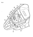
- the first tank-side pipe passage part 84a and the second tank-side pipe passage part 84b are connected to each other such that the first tank-side pipe passage part 84a and the second tank-side pipe passage part 84b surround the periphery of the fuel filling port 67, a part of the first tank-side pipe passage part 84a and a part of the second tank-side pipe passage part 84b are arranged so as to pass below the tray 70 which receives fuel spilled from the fuel filling port 67.
- a Part which constitutes the portion of the first tank-side pipe passage part 84a and the portion of the second tank-side pipe passage part 84b and passes below the tray 70 is formed of a metallic pipe 86 which is bent so as to surround a part of the fuel filling sleeve 68.
- two portions of the metallic pipe 86 are held by pipe holding members 87, 87.
- Mounting members 88, 88 are welded to the higher part 81 of the upper surface of the fuel tank 42 corresponding to the pipe holding members 87 ..., and the pipe holding members 87 ... are mounted on the mounting members 88 ... by bolts 89 ... and nuts 90 ....
- Painting treatment is applied to the fuel tank 42 including the mounting members 88 ..., and the metallic pipe 86 is fastened to the fuel tank 42 to which the painting treatment is applied.
- a part of the third tank-side pipe passage part 84c which includes at least the highest part 91 is formed of an elastic tube 92, and the highest part 91 of the elastic tube 92 is supported on a highest part support part 93 mounted on the fuel tank 42 from below.
- the highest part support part 93 is arranged below the right side part 80b of the bulging part 80 which is formed on the tank cover 44 so that a relatively large empty space is formed above the highest part support part 93.
- a rib 44b which prevents the elastic tube 92 from being upwardly removed from the upper open clamper 95 is integrally formed on the tank cover 44 such that the rib 44b traverses the inside of the right side part 80b. It is desirable that the rib 44b is arranged just above the upper open clamper 95.
- the upper open clampers 98, 99 are fixedly mounted in common on a support plate 100 which is fixedly mounted on the upper surface of the fuel tank 42.
- the removal of the elastic tubes 92, 97 from the upper open clampers 95, 98, 99 mounted on the upper surface of the fuel tank 42 is prevented by the tank cover 44 which covers the fuel tank 42 from above.
- a branch part 101 is formed on the third tank-side pipe passage part 84c of the charge pipe passage 84 at a position closer to the fuel tank 42 side than the first check valve 96.
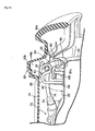
- An atmospheric air introducing pipe passage 102 which introduces atmospheric air to the inside of the fuel tank 42 is connected to the branch part 101, and a second check valve 103 which prevents the flow of a fuel gas from the fuel tank 42 side is interposed on the atmospheric air introducing pipe passage 102. Further, as clearly shown in Fig. 10 , the second check valve 103 is arranged at a position higher than the highest part 91 of the charge pipe passage 84.
- a filter 104 is interposed on the atmospheric air introducing pipe passage 102 at a position closer to an atmospheric air open side, that is, a connection part 16 side than the second check valve 103.
- the filter 104 is interposed on a portion of the atmospheric air introducing pipe passage 102 which has a downward gradient toward the atmospheric air open side, that is, the connection part 16 side.
- the atmospheric air introducing pipe passage 102 includes an elastic tube 105 which has one end portion thereof connected to the branch part 101 and the other end portion thereof connected to the second check valve 103, an elastic tube 106 which has one end portion thereof connected to the second check valve 103 and the other end thereof connected to the filter 104, and an elastic tube 107 which has one end portion thereof connected to the filter 104 and the other end portion thereof connected to the connection part 16 of the vehicle body frame F.
- the elastic tube 106 is arranged in an arcuately bent shape while connecting the second check valve 103 and the filter 104 arranged at an oblique rearward and downward position from the second check valve 103, and a part of the elastic tube 106 and the elastic tube 107 are arranged such that these parts have a downward gradient toward the connection part 16 while connecting the filter 104 therebetween.
- the other end portion of the elastic tube 105 and one end portion of the elastic tube 106 are held by the upper open clampers 108, 109 at a position where the second check valve 103 is sandwiched between the elastic tube 105 and the elastic tube 106.
- These upper open clampers 108, 109 are fixedly mounted on the fifth stay 56 which constitutes a part of the vehicle body frame F so that the removal of the elastic tubes 105, 106 from these upper open clampers 108, 109 can be prevented by the tank cover 44 which covers the fuel tank 42 from above.
- the second check valve 104 is arranged below the rear part 80a which receives a load from the rider's seat 40 out of the bulging part 80 formed on the tank cover 44 which covers the fuel tank 42 from above.
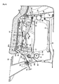
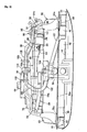
- the charge pipe passage 84 includes: a communication pipe passage part 84d which is connected to the third tank-side pipe passage part 84c on the other side in the vehicle widthwise direction (a right side in this embodiment) and extends toward one side in the vehicle widthwise direction (a left side in this embodiment) along the second cross member 38; a first engine-side pipe passage part 84e which is connected to the communication pipe passage part 84d and is arranged above the engine body 19 in a vertically extending manner on the one side in the vehicle widthwise direction; a second engine-side pipe passage part 84f which is connected to a lower end of the first engine-side pipe passage part 84e on the one side in the vehicle widthwise direction and extends from the one side to the other side in the vehicle widthwise direction above the engine body 19; and a third engine-side pipe passage part 84g which is connected to the second engine-side pipe passage part 84f on the other side in the vehicle widthwise direction and is connected to the engine body 19.
- the communication pipe passage part 84d is connected to the third tank-side pipe passage part 84c on the right side in the vehicle widthwise direction and extends leftwardly in the vehicle widthwise direction along the second cross member 38.
- the communication pipe passage part 84d is connected to an upper end of the first engine-side pipe passage part 84e on the left side in the vehicle widthwise direction and extends rightwardly in the vehicle widthwise direction along the second cross member 38 and is connected to the fuel tank 42 through the third, the second and the first tank-side pipe passage parts 84c, 84b, 84a.
- the first engine-side pipe passage part 84e extends in the vertical direction on the left side in the vehicle widthwise direction
- the second engine-side pipe passage part 84f is arranged in an extending manner from the left side to the right side in the vehicle widthwise direction above the engine body 19
- the third engine-side pipe passage part 84g is connected to the crankcase 20 of the engine body 19 on the right side in the vehicle widthwise direction.
- a frame-side support part 110 which supports an intermediate part of the first engine-side pipe passage part 84e is mounted on the vehicle body frame F, and on an upper surface of the shroud 25 of the engine E, an engine-side support part 111 which supports an intermediate part of the second engine-side pipe passage part 84f is mounted.
- the engine-side support part 111 is mounted on the upper surface of the shroud 25 together with the fuel supply tube support member 77 by bolts 112.
- the elastic tube 97 which forms a part of the third tank-side pipe passage part 84c and has one end portion thereof connected to the first check valve 96 constitutes the whole communication pipe passage part 84d, the whole first engine-side pipe passage part 84e, the whole second engine-side pipe passage part 84f and a part of the third engine-side pipe passage part 84g.
- the third engine-side pipe passage part 84g is connected to the crankcase 20 in such a manner that the third engine-side pipe passage part 84g is arranged adjacent to, inside in the vehicle widthwise direction, a fuel supply pipe 116 which is arranged on a right side part of the crankcase 20 for supplying oil to the inside of the crankcase 20 of the engine body 19, extends obliquely in the upward direction, and has an upper end portion thereof closed by a cap 115.
- the third engine-side pipe passage part 84g is constituted of a part of the elastic tube 97, and a metallic tubular body 117 which has an upper end portion thereof connected to the elastic tube 97 and is fixedly mounted on the crankcase 20.
- the fuel filling port 67 is formed in the upper surface of the fuel tank 42 on one side in the vehicle widthwise direction (left side in this embodiment), and the first tank-side pipe passage part 84a which is connected to the upper surface of the fuel tank 42 at a position offset from the fuel filling port 67 and the second tank-side pipe passage part 84b are connected to each other in a state where the first tank-side pipe passage part 84a and the second tank-side pipe passage part 84b surround the periphery of the fuel filling port 67.
- the part of the first tank-side pipe passage part 84a and the part of the second tank-side pipe passage part 84b can be arranged with large curvatures respectively by making use of a dead space around the fuel filling port 67 thus easing the arrangement of the first tank-side pipe passage part 84a and the second tank-side pipe passage part 84b.
- the tray 70 which receives fuel spilt from the fuel filling port 67 is arranged around the fuel filling port 67, and the part of the first tank-side pipe passage part 84a and the part of the second tank-side pipe passage part 84b are arranged to pass below the tray 70. Accordingly, even when the part of the first tank-side pipe passage part 84a and the part of the second tank-side pipe passage part 84b are arranged so as to surround the fuel filling port 67, an area of the tray 70 can be increased.
- the charge pipe passage 84 is connected to the second tank-side pipe passage part 84b on the other side in the vehicle widthwise direction (right side in this embodiment), and includes the third tank-side pipe passage part 84c which has the highest part 91 arranged at the highest position of the charge pipe passage 84 at the intermediated position thereof. Accordingly, the flowout of fuel when the motorcycle falls can be more effectively suppressed.
- the part of the third tank-side pipe passage part 84c which includes at least the highest part 91 is formed of the elastic tube 92, and the highest part 91 of the elastic tube 92 is supported on the highest part support part 93 mounted on the fuel tank 42 from below. Accordingly, the degree of freedom in design can be enhanced by determining the height of the highest part 91 based on the height of the highest part support part 93. Further, the part of the charge pipe passage 84 ranging from the highest part 91 to the connection part 85 with the fuel tank 42 is arranged with a downward gradient toward the connection part 85 side. Accordingly, fuel stored in the charge pipe passage 84 between the highest part 91 and the fuel tank 42 can be easily returned to the fuel tank 42 side.
- the downstream end of the charge pipe passage 84 is connected to the crankcase 20 in a state where the downstream end of the charge pipe passage 84 opens in the oil in the crankcase 20, and the first check valve 96 which prevents a backflow of a fuel gas toward the fuel tank 42 is interposed on a portion of the charge pipe passage 84 downstream of the highest part 91. Accordingly, it is possible to effectively prevent oil in the crankcase 20 from flowing toward the fuel tank 42 by the first check valve 96, and it is also possible to enhance assembling property by supporting the first check valve 96 on the fuel tank 42.
- the upper surface of the fuel tank 42 includes the higher part 81 in which the fuel filling port 67 is formed and the lower part 82 lower than the higher part 81, and the first check valve 96 is arranged on the lower part 82. Accordingly, it is possible to prevent the first check valve 96 from taking the high arrangement position. Further, the lower part 82 is formed in a downwardly inclined manner toward the crankcase 20. Accordingly, it is possible to make the flow of a fuel gas which passes through the first check valve 96 smooth.
- the atmospheric air introducing pipe 102 which introduces an atmospheric air to the inside of the fuel tank 42 is connected to the branch part 101 which is formed on the third tank-side pipe passage part 84c of the charge pipe passage 84 at a position closer to the fuel tank 42 side than the first check valve 96, and the second check valve 103 which prevents the flow of fuel from the fuel tank 42 side is interposed on the atmospheric air introducing pipe 102. Accordingly, when the pressure inside the fuel tank 42 becomes a negative pressure, atmospheric air is introduced into the inside of the fuel tank 42 so as to adjust the pressure in the fuel tank 42 to an atmospheric pressure. Further, it is possible to prevent a fuel gas from being discharged to the outside through the atmospheric air introducing pipe 102 by the second check valve 103.
- the parts of the elastic tubes 92, 97 which constitute at least a part of the charge pipe passage 84 and are arranged above the fuel tank 42 are held by the upper open clampers 95, 98, 99 which are mounted on the upper surface of the fuel tank 42, and the fuel tank 42 is covered with the tank cover 44 which prevents the removal of the elastic tubes 92, 97 from the upper open clampers 95, 98, 99. Accordingly, the part of the charge pipe passage 84 can be supported on the fuel tank 42 with the simple structure and hence, the assembling property can be enhanced.
- Paint treatment is applied to the outer surface of the fuel tank 42, and the metallic pipe 86 which constitutes the part of the charge pipe passage 84 is fastened to the fuel tank 42. Accordingly, compared to a case where the metallic pipe 86 is fixed to the fuel tank 42 by welding, it is unnecessary to apply masking to the metallic pipe 86 and hence, a painting cost can be reduced.
- the branch part 101 is arranged on the third tank-side pipe passage part 84c at the position closer to the fuel tank 42 side than the highest part 91. Accordingly, when fuel flown out from the fuel tank 42 flows into the atmospheric air introducing pipe passage 102 at the connection part with the charge pipe passage 84, that is, between the branch part 101 and the second check valve 103 when a motorcycle falls, fuel in the atmospheric air introducing pipe passage 102 returns to a position upstream of the highest part 91 of the charge pipe passage 84 when the motorcycle is raised after falling and hence, the flow of fuel toward the engine body 19 can be prevented.
- the atmospheric air introducing pipe passage 102 opens in atmospheric air below the second check valve 103. Accordingly, even when water enters the inside of the atmospheric air introducing pipe passage 102 through an atmospheric air open end of the atmospheric air introducing pipe passage 102, it is possible to make water which enters the atmospheric air introducing pipe passage 102 difficult to reach the second check valve 103.
- the filter 104 is interposed on the atmospheric air introducing pipe passage 102 at a position closer to the atmospheric air open side than the second check valve 103 and hence, dusts hardly adhere to the second check valve 103.
- the filter 104 is interposed on a part of the atmospheric air introducing pipe passage 102 which has a downward gradient toward the atmospheric air open side and hence, even when the filter 104 is wetted with water, it is possible to drain water toward the atmospheric air open end side from the filter 104.
- the bulging part 80 which receives a load from the rider's seat 40 and dams up fuel overflown to the outside of the opening part 79 at the time of filling fuel to the fuel filling port 67 from above is formed in an upwardly bulging manner, and the second check valve 103 is arranged below the bulging part 80. Accordingly, the second check valve 103 is arranged at a high position and hence, it is possible to make water which enters the inside of the atmospheric air introducing pipe passage 102 more difficult to reach the second check valve 103.
- the charge pipe passage 84 includes: the first engine-side pipe passage part 84e which is arranged above the engine body 19 in a vertically extending manner on one side in the vehicle widthwise direction (left side in this embodiment) of the engine body 19; the second engine-side pipe passage part 84f which is connected to the lower end of the first engine-side pipe passage part 84e on the one side in the vehicle widthwise direction and extends from the one side to the other side in the vehicle widthwise direction (right side in this embodiment) above the engine body 19; and the third engine-side pipe passage part 84g which is connected to the second engine-side pipe passage part 84f on the other side in the vehicle widthwise direction and is connected to the engine body 19. Accordingly, it is possible to suppress the flow out of oil in the engine body 19 to the inside of the charge pipe passage 84 when the motorcycle falls.
- the frame-side support part 110 which supports the first engine-side pipe passage part 84e is mounted on the vehicle body frame F
- the engine-side support part 111 which supports the second engine-side pipe passage part 84f is mounted on the shroud 25 of the engine E
- at least a part of the charge pipe passage 84 between the engine-side support part 111 and the frame-side support part 110 is formed of the elastic tube 97 and hence, the charge pipe passage 84 can follow the swing of the engine E.
- the second engine-side pipe passage part 84f is arranged so as to pass below the intake device 28 which extends rearwardly from an upper side surface of the cylinder head 22 of the engine body 19 and hence, a part of the charge pipe passage 84 can be arranged by making use of a dead space below the intake device 28.
- the engine-side support part 111 is mounted on the engine E at a position closer to one side in the vehicle widthwise direction than the intake device 28 as viewed in a plan view. Accordingly, a part of the charge pipe passage 84 which passes below the intake device, that is, the second engine-side pipe passage part 84f can be fixed such that the second engine-side pipe passage part 84f does not swing relative to the engine body 19 and hence, the intake device 28 can be arranged close to the engine body 19 while obviating the contact of the intake device 28 with the charge pipe passage 84 thus contributing to making the engine E compact.
- the vehicle body frame F includes the pair of left and right seat frames 15 ... which have the inclined parts 15a ... extending rearwardly and upwardly respectively, the power unit P is swingably supported on the vehicle body frame F below the seat frames 15 ..., and the frame-side support part 110 is arranged at an oblique rearward and upward position from the engine-side support part 111 and is mounted on the inclined part 15a of the seat frame 15 on one side in the vehicle widthwise direction (left side in this embodiment) out of both seat frames 15 ....
- the engine-side support part 111 and the frame-side support part 110 can be arranged in a spaced-apart manner from each other in the longitudinal direction and hence, a diffraction amount of the elastic tube 97 caused by the swing of the power unit P can be made small.
- the second cross member 38 is provided between the pair of seat frames 15 ... behind the frame-side support part 110, the fuel tank 42 which is arranged behind the second cross member 38 is supported on the both seat frames 15 ..., and the charge pipe passage 84 includes the communication pipe passage part 84d which is communicably connected to the upper end of the first engine-side pipe passage part 84e on one side in the vehicle widthwise direction, extends toward the other side in the vehicle widthwise direction along the second cross member 38, and is connected to the fuel tank 42. Accordingly, the flowout of oil into the inside of the charge pipe passage 84 from the engine body 19 side can be more effectively suppressed.
- the invention described in Claims 1 to 7 is also applicable to a motorcycle where a canister which constitutes the fuel absorption means is arranged below the upper surface of the fuel tank 42.
Landscapes
- Engineering & Computer Science (AREA)
- Mechanical Engineering (AREA)
- Cooling, Air Intake And Gas Exhaust, And Fuel Tank Arrangements In Propulsion Units (AREA)
- Supplying Secondary Fuel Or The Like To Fuel, Air Or Fuel-Air Mixtures (AREA)
Applications Claiming Priority (1)
| Application Number | Priority Date | Filing Date | Title |
|---|---|---|---|
| JP2011063113A JP5837314B2 (ja) | 2011-03-22 | 2011-03-22 | 自動二輪車における蒸発燃料処理装置 |
Publications (2)
| Publication Number | Publication Date |
|---|---|
| EP2502812A1 true EP2502812A1 (de) | 2012-09-26 |
| EP2502812B1 EP2502812B1 (de) | 2013-03-13 |
Family
ID=45495760
Family Applications (1)
| Application Number | Title | Priority Date | Filing Date |
|---|---|---|---|
| EP20120150608 Not-in-force EP2502812B1 (de) | 2011-03-22 | 2012-01-10 | Vorrichtung zur Behandlung von verdunstetem Kraftstoff für Motorräder |
Country Status (6)
| Country | Link |
|---|---|
| US (1) | US8875684B2 (de) |
| EP (1) | EP2502812B1 (de) |
| JP (1) | JP5837314B2 (de) |
| CN (1) | CN102691597B (de) |
| CA (1) | CA2769934C (de) |
| TW (1) | TWI493104B (de) |
Families Citing this family (8)
| Publication number | Priority date | Publication date | Assignee | Title |
|---|---|---|---|---|
| JP5303679B2 (ja) * | 2010-02-22 | 2013-10-02 | 本田技研工業株式会社 | 鞍乗り型車両の蒸発燃料制御装置 |
| JP5634290B2 (ja) * | 2011-02-09 | 2014-12-03 | 本田技研工業株式会社 | 鞍乗り型車両 |
| JP5835684B2 (ja) * | 2011-03-22 | 2015-12-24 | 本田技研工業株式会社 | 自動二輪車における蒸発燃料処理装置 |
| JP5835685B2 (ja) * | 2011-03-22 | 2015-12-24 | 本田技研工業株式会社 | 自動二輪車における蒸発燃料処理装置 |
| JP6175013B2 (ja) * | 2014-02-28 | 2017-08-02 | 本田技研工業株式会社 | 自動二輪車の燃料供給配管配置構造 |
| US9809110B2 (en) * | 2014-12-30 | 2017-11-07 | Yamaha Hatsudoki Kabushiki Kaisha | Saddle-riding type vehicle |
| USD800781S1 (en) * | 2016-08-22 | 2017-10-24 | Harley-Davidson Motor Company Group, LLC | Engine primary cover |
| JP7250478B2 (ja) * | 2018-11-02 | 2023-04-03 | カワサキモータース株式会社 | 鞍乗型車両 |
Citations (4)
| Publication number | Priority date | Publication date | Assignee | Title |
|---|---|---|---|---|
| JP4108954B2 (ja) | 2001-10-05 | 2008-06-25 | ヤマハ発動機株式会社 | 自動二輪車の燃料系配置構造 |
| JP2010076662A (ja) * | 2008-09-26 | 2010-04-08 | Honda Motor Co Ltd | 自動二輪車 |
| EP2206910A1 (de) * | 2008-12-26 | 2010-07-14 | Honda Motor Co., Ltd | Fahrzeug mit Sattel |
| EP2216239A1 (de) * | 2009-02-04 | 2010-08-11 | Yamaha Hatsudoki Kabushiki Kaisha | Motorrad |
Family Cites Families (14)
| Publication number | Priority date | Publication date | Assignee | Title |
|---|---|---|---|---|
| JPS4988172U (de) * | 1972-11-21 | 1974-07-31 | ||
| JP3889214B2 (ja) * | 2000-09-29 | 2007-03-07 | 本田技研工業株式会社 | 車両用燃料供給装置 |
| JP4014907B2 (ja) * | 2002-03-27 | 2007-11-28 | 日新製鋼株式会社 | 耐食性に優れたステンレス鋼製の自動車用燃料タンクおよび給油管 |
| JP2005061305A (ja) * | 2003-08-11 | 2005-03-10 | Nippon Soken Inc | 内燃機関の蒸発燃料処理方法および蒸発燃料処理装置とその故障診断装置 |
| US20060086404A1 (en) * | 2004-10-26 | 2006-04-27 | Wu Hsiao C | Gas adaptor installed to an opening of a fuel tank of small engines equipments |
| JP2010203313A (ja) * | 2009-03-03 | 2010-09-16 | Honda Motor Co Ltd | 不整地走行車両の蒸発燃料制御装置 |
| JP5315109B2 (ja) * | 2009-03-30 | 2013-10-16 | 本田技研工業株式会社 | 車両のキャニスタの大気開放構造 |
| JP5280273B2 (ja) * | 2009-03-30 | 2013-09-04 | 本田技研工業株式会社 | 鞍乗り型車両のキャニスタの配置構造 |
| JP5301374B2 (ja) * | 2009-06-30 | 2013-09-25 | 本田技研工業株式会社 | 自動2輪車 |
| JP5390978B2 (ja) * | 2009-07-31 | 2014-01-15 | 本田技研工業株式会社 | 自動二輪車の蒸発燃料処理装置 |
| JP5232752B2 (ja) * | 2009-09-30 | 2013-07-10 | 本田技研工業株式会社 | 鞍乗り型車両の蒸発燃料処理装置の配置構造 |
| JP5364799B2 (ja) * | 2010-01-06 | 2013-12-11 | 本田技研工業株式会社 | 内燃機関への蒸発燃料の案内装置 |
| WO2011083514A1 (ja) * | 2010-01-08 | 2011-07-14 | 本田技研工業株式会社 | 鞍乗り型車両の蒸発燃料制御装置 |
| CN201633532U (zh) * | 2010-03-16 | 2010-11-17 | 力帆实业(集团)股份有限公司 | 油箱 |
-
2011
- 2011-03-22 JP JP2011063113A patent/JP5837314B2/ja not_active Expired - Fee Related
-
2012
- 2012-01-10 EP EP20120150608 patent/EP2502812B1/de not_active Not-in-force
- 2012-02-29 CA CA2769934A patent/CA2769934C/en not_active Expired - Fee Related
- 2012-03-20 TW TW101109515A patent/TWI493104B/zh not_active IP Right Cessation
- 2012-03-20 US US13/424,944 patent/US8875684B2/en active Active
- 2012-03-21 CN CN201210075187.2A patent/CN102691597B/zh not_active Expired - Fee Related
Patent Citations (4)
| Publication number | Priority date | Publication date | Assignee | Title |
|---|---|---|---|---|
| JP4108954B2 (ja) | 2001-10-05 | 2008-06-25 | ヤマハ発動機株式会社 | 自動二輪車の燃料系配置構造 |
| JP2010076662A (ja) * | 2008-09-26 | 2010-04-08 | Honda Motor Co Ltd | 自動二輪車 |
| EP2206910A1 (de) * | 2008-12-26 | 2010-07-14 | Honda Motor Co., Ltd | Fahrzeug mit Sattel |
| EP2216239A1 (de) * | 2009-02-04 | 2010-08-11 | Yamaha Hatsudoki Kabushiki Kaisha | Motorrad |
Also Published As
| Publication number | Publication date |
|---|---|
| EP2502812B1 (de) | 2013-03-13 |
| US8875684B2 (en) | 2014-11-04 |
| TWI493104B (zh) | 2015-07-21 |
| CN102691597A (zh) | 2012-09-26 |
| CA2769934C (en) | 2013-08-13 |
| JP5837314B2 (ja) | 2015-12-24 |
| TW201305430A (zh) | 2013-02-01 |
| US20120240905A1 (en) | 2012-09-27 |
| JP2012197742A (ja) | 2012-10-18 |
| CN102691597B (zh) | 2015-10-28 |
| CA2769934A1 (en) | 2012-09-22 |
Similar Documents
| Publication | Publication Date | Title |
|---|---|---|
| EP2502812B1 (de) | Vorrichtung zur Behandlung von verdunstetem Kraftstoff für Motorräder | |
| EP2305545B1 (de) | Rollerartiges Fahrzeug | |
| CN101791997B (zh) | 摩托车 | |
| US8534406B2 (en) | Motorcycle | |
| CN101850812A (zh) | 跨骑型车辆的过滤罐的配置构造 | |
| CN102597482A (zh) | 机动两轮车 | |
| EP2502811B1 (de) | Vorrichtung zur Behandlung von verdunstetem Kraftstoff für Motorräder | |
| EP2502813B1 (de) | Vorrichtung zur Behandlung von verdunstetem Kraftstoff für Motorräder | |
| EP2824023B1 (de) | Motorrad | |
| JP5620662B2 (ja) | 自動二輪車 | |
| JP6138609B2 (ja) | 自動二輪車の後部フレーム構造 | |
| CN111448128A (zh) | 跨骑型车辆 | |
| JP2009226987A (ja) | スクータ型車両の吸気装置 |
Legal Events
| Date | Code | Title | Description |
|---|---|---|---|
| PUAI | Public reference made under article 153(3) epc to a published international application that has entered the european phase |
Free format text: ORIGINAL CODE: 0009012 |
|
| 17P | Request for examination filed |
Effective date: 20120110 |
|
| AK | Designated contracting states |
Kind code of ref document: A1 Designated state(s): AL AT BE BG CH CY CZ DE DK EE ES FI FR GB GR HR HU IE IS IT LI LT LU LV MC MK MT NL NO PL PT RO RS SE SI SK SM TR |
|
| AX | Request for extension of the european patent |
Extension state: BA ME |
|
| RIC1 | Information provided on ipc code assigned before grant |
Ipc: B62J 37/00 20060101ALI20120925BHEP Ipc: B62J 35/00 20060101AFI20120925BHEP |
|
| GRAP | Despatch of communication of intention to grant a patent |
Free format text: ORIGINAL CODE: EPIDOSNIGR1 |
|
| GRAS | Grant fee paid |
Free format text: ORIGINAL CODE: EPIDOSNIGR3 |
|
| GRAA | (expected) grant |
Free format text: ORIGINAL CODE: 0009210 |
|
| AK | Designated contracting states |
Kind code of ref document: B1 Designated state(s): AL AT BE BG CH CY CZ DE DK EE ES FI FR GB GR HR HU IE IS IT LI LT LU LV MC MK MT NL NO PL PT RO RS SE SI SK SM TR |
|
| REG | Reference to a national code |
Ref country code: GB Ref legal event code: FG4D |
|
| REG | Reference to a national code |
Ref country code: AT Ref legal event code: REF Ref document number: 600628 Country of ref document: AT Kind code of ref document: T Effective date: 20130315 Ref country code: CH Ref legal event code: EP |
|
| REG | Reference to a national code |
Ref country code: IE Ref legal event code: FG4D |
|
| REG | Reference to a national code |
Ref country code: DE Ref legal event code: R096 Ref document number: 602012000015 Country of ref document: DE Effective date: 20130508 |
|
| PG25 | Lapsed in a contracting state [announced via postgrant information from national office to epo] |
Ref country code: ES Free format text: LAPSE BECAUSE OF FAILURE TO SUBMIT A TRANSLATION OF THE DESCRIPTION OR TO PAY THE FEE WITHIN THE PRESCRIBED TIME-LIMIT Effective date: 20130624 Ref country code: SE Free format text: LAPSE BECAUSE OF FAILURE TO SUBMIT A TRANSLATION OF THE DESCRIPTION OR TO PAY THE FEE WITHIN THE PRESCRIBED TIME-LIMIT Effective date: 20130313 Ref country code: NO Free format text: LAPSE BECAUSE OF FAILURE TO SUBMIT A TRANSLATION OF THE DESCRIPTION OR TO PAY THE FEE WITHIN THE PRESCRIBED TIME-LIMIT Effective date: 20130613 Ref country code: LT Free format text: LAPSE BECAUSE OF FAILURE TO SUBMIT A TRANSLATION OF THE DESCRIPTION OR TO PAY THE FEE WITHIN THE PRESCRIBED TIME-LIMIT Effective date: 20130313 Ref country code: BG Free format text: LAPSE BECAUSE OF FAILURE TO SUBMIT A TRANSLATION OF THE DESCRIPTION OR TO PAY THE FEE WITHIN THE PRESCRIBED TIME-LIMIT Effective date: 20130613 |
|
| REG | Reference to a national code |
Ref country code: AT Ref legal event code: MK05 Ref document number: 600628 Country of ref document: AT Kind code of ref document: T Effective date: 20130313 |
|
| REG | Reference to a national code |
Ref country code: NL Ref legal event code: VDEP Effective date: 20130313 |
|
| REG | Reference to a national code |
Ref country code: LT Ref legal event code: MG4D |
|
| PG25 | Lapsed in a contracting state [announced via postgrant information from national office to epo] |
Ref country code: LV Free format text: LAPSE BECAUSE OF FAILURE TO SUBMIT A TRANSLATION OF THE DESCRIPTION OR TO PAY THE FEE WITHIN THE PRESCRIBED TIME-LIMIT Effective date: 20130313 Ref country code: GR Free format text: LAPSE BECAUSE OF FAILURE TO SUBMIT A TRANSLATION OF THE DESCRIPTION OR TO PAY THE FEE WITHIN THE PRESCRIBED TIME-LIMIT Effective date: 20130614 Ref country code: SI Free format text: LAPSE BECAUSE OF FAILURE TO SUBMIT A TRANSLATION OF THE DESCRIPTION OR TO PAY THE FEE WITHIN THE PRESCRIBED TIME-LIMIT Effective date: 20130313 Ref country code: FI Free format text: LAPSE BECAUSE OF FAILURE TO SUBMIT A TRANSLATION OF THE DESCRIPTION OR TO PAY THE FEE WITHIN THE PRESCRIBED TIME-LIMIT Effective date: 20130313 |
|
| PG25 | Lapsed in a contracting state [announced via postgrant information from national office to epo] |
Ref country code: BE Free format text: LAPSE BECAUSE OF FAILURE TO SUBMIT A TRANSLATION OF THE DESCRIPTION OR TO PAY THE FEE WITHIN THE PRESCRIBED TIME-LIMIT Effective date: 20130313 Ref country code: HR Free format text: LAPSE BECAUSE OF FAILURE TO SUBMIT A TRANSLATION OF THE DESCRIPTION OR TO PAY THE FEE WITHIN THE PRESCRIBED TIME-LIMIT Effective date: 20130313 Ref country code: RS Free format text: LAPSE BECAUSE OF FAILURE TO SUBMIT A TRANSLATION OF THE DESCRIPTION OR TO PAY THE FEE WITHIN THE PRESCRIBED TIME-LIMIT Effective date: 20130313 |
|
| PG25 | Lapsed in a contracting state [announced via postgrant information from national office to epo] |
Ref country code: IS Free format text: LAPSE BECAUSE OF FAILURE TO SUBMIT A TRANSLATION OF THE DESCRIPTION OR TO PAY THE FEE WITHIN THE PRESCRIBED TIME-LIMIT Effective date: 20130713 Ref country code: PT Free format text: LAPSE BECAUSE OF FAILURE TO SUBMIT A TRANSLATION OF THE DESCRIPTION OR TO PAY THE FEE WITHIN THE PRESCRIBED TIME-LIMIT Effective date: 20130715 Ref country code: CZ Free format text: LAPSE BECAUSE OF FAILURE TO SUBMIT A TRANSLATION OF THE DESCRIPTION OR TO PAY THE FEE WITHIN THE PRESCRIBED TIME-LIMIT Effective date: 20130313 Ref country code: EE Free format text: LAPSE BECAUSE OF FAILURE TO SUBMIT A TRANSLATION OF THE DESCRIPTION OR TO PAY THE FEE WITHIN THE PRESCRIBED TIME-LIMIT Effective date: 20130313 Ref country code: SK Free format text: LAPSE BECAUSE OF FAILURE TO SUBMIT A TRANSLATION OF THE DESCRIPTION OR TO PAY THE FEE WITHIN THE PRESCRIBED TIME-LIMIT Effective date: 20130313 Ref country code: NL Free format text: LAPSE BECAUSE OF FAILURE TO SUBMIT A TRANSLATION OF THE DESCRIPTION OR TO PAY THE FEE WITHIN THE PRESCRIBED TIME-LIMIT Effective date: 20130313 Ref country code: RO Free format text: LAPSE BECAUSE OF FAILURE TO SUBMIT A TRANSLATION OF THE DESCRIPTION OR TO PAY THE FEE WITHIN THE PRESCRIBED TIME-LIMIT Effective date: 20130313 Ref country code: AT Free format text: LAPSE BECAUSE OF FAILURE TO SUBMIT A TRANSLATION OF THE DESCRIPTION OR TO PAY THE FEE WITHIN THE PRESCRIBED TIME-LIMIT Effective date: 20130313 |
|
| PG25 | Lapsed in a contracting state [announced via postgrant information from national office to epo] |
Ref country code: PL Free format text: LAPSE BECAUSE OF FAILURE TO SUBMIT A TRANSLATION OF THE DESCRIPTION OR TO PAY THE FEE WITHIN THE PRESCRIBED TIME-LIMIT Effective date: 20130313 |
|
| PLBE | No opposition filed within time limit |
Free format text: ORIGINAL CODE: 0009261 |
|
| STAA | Information on the status of an ep patent application or granted ep patent |
Free format text: STATUS: NO OPPOSITION FILED WITHIN TIME LIMIT |
|
| PG25 | Lapsed in a contracting state [announced via postgrant information from national office to epo] |
Ref country code: DK Free format text: LAPSE BECAUSE OF FAILURE TO SUBMIT A TRANSLATION OF THE DESCRIPTION OR TO PAY THE FEE WITHIN THE PRESCRIBED TIME-LIMIT Effective date: 20130313 |
|
| 26N | No opposition filed |
Effective date: 20131216 |
|
| REG | Reference to a national code |
Ref country code: DE Ref legal event code: R097 Ref document number: 602012000015 Country of ref document: DE Effective date: 20131216 |
|
| PG25 | Lapsed in a contracting state [announced via postgrant information from national office to epo] |
Ref country code: LU Free format text: LAPSE BECAUSE OF FAILURE TO SUBMIT A TRANSLATION OF THE DESCRIPTION OR TO PAY THE FEE WITHIN THE PRESCRIBED TIME-LIMIT Effective date: 20140110 |
|
| REG | Reference to a national code |
Ref country code: IE Ref legal event code: MM4A |
|
| PG25 | Lapsed in a contracting state [announced via postgrant information from national office to epo] |
Ref country code: IE Free format text: LAPSE BECAUSE OF NON-PAYMENT OF DUE FEES Effective date: 20140110 |
|
| PG25 | Lapsed in a contracting state [announced via postgrant information from national office to epo] |
Ref country code: MC Free format text: LAPSE BECAUSE OF FAILURE TO SUBMIT A TRANSLATION OF THE DESCRIPTION OR TO PAY THE FEE WITHIN THE PRESCRIBED TIME-LIMIT Effective date: 20130313 |
|
| REG | Reference to a national code |
Ref country code: CH Ref legal event code: PL |
|
| PG25 | Lapsed in a contracting state [announced via postgrant information from national office to epo] |
Ref country code: CH Free format text: LAPSE BECAUSE OF NON-PAYMENT OF DUE FEES Effective date: 20150131 Ref country code: LI Free format text: LAPSE BECAUSE OF NON-PAYMENT OF DUE FEES Effective date: 20150131 |
|
| REG | Reference to a national code |
Ref country code: FR Ref legal event code: PLFP Year of fee payment: 5 |
|
| PG25 | Lapsed in a contracting state [announced via postgrant information from national office to epo] |
Ref country code: MT Free format text: LAPSE BECAUSE OF FAILURE TO SUBMIT A TRANSLATION OF THE DESCRIPTION OR TO PAY THE FEE WITHIN THE PRESCRIBED TIME-LIMIT Effective date: 20130313 |
|
| PG25 | Lapsed in a contracting state [announced via postgrant information from national office to epo] |
Ref country code: SM Free format text: LAPSE BECAUSE OF FAILURE TO SUBMIT A TRANSLATION OF THE DESCRIPTION OR TO PAY THE FEE WITHIN THE PRESCRIBED TIME-LIMIT Effective date: 20130313 |
|
| PG25 | Lapsed in a contracting state [announced via postgrant information from national office to epo] |
Ref country code: CY Free format text: LAPSE BECAUSE OF FAILURE TO SUBMIT A TRANSLATION OF THE DESCRIPTION OR TO PAY THE FEE WITHIN THE PRESCRIBED TIME-LIMIT Effective date: 20130313 |
|
| PG25 | Lapsed in a contracting state [announced via postgrant information from national office to epo] |
Ref country code: TR Free format text: LAPSE BECAUSE OF FAILURE TO SUBMIT A TRANSLATION OF THE DESCRIPTION OR TO PAY THE FEE WITHIN THE PRESCRIBED TIME-LIMIT Effective date: 20130313 Ref country code: HU Free format text: LAPSE BECAUSE OF FAILURE TO SUBMIT A TRANSLATION OF THE DESCRIPTION OR TO PAY THE FEE WITHIN THE PRESCRIBED TIME-LIMIT; INVALID AB INITIO Effective date: 20120110 |
|
| GBPC | Gb: european patent ceased through non-payment of renewal fee |
Effective date: 20160110 |
|
| PG25 | Lapsed in a contracting state [announced via postgrant information from national office to epo] |
Ref country code: GB Free format text: LAPSE BECAUSE OF NON-PAYMENT OF DUE FEES Effective date: 20160110 |
|
| REG | Reference to a national code |
Ref country code: FR Ref legal event code: PLFP Year of fee payment: 6 |
|
| REG | Reference to a national code |
Ref country code: FR Ref legal event code: PLFP Year of fee payment: 7 |
|
| PG25 | Lapsed in a contracting state [announced via postgrant information from national office to epo] |
Ref country code: MK Free format text: LAPSE BECAUSE OF FAILURE TO SUBMIT A TRANSLATION OF THE DESCRIPTION OR TO PAY THE FEE WITHIN THE PRESCRIBED TIME-LIMIT Effective date: 20130313 |
|
| PG25 | Lapsed in a contracting state [announced via postgrant information from national office to epo] |
Ref country code: AL Free format text: LAPSE BECAUSE OF FAILURE TO SUBMIT A TRANSLATION OF THE DESCRIPTION OR TO PAY THE FEE WITHIN THE PRESCRIBED TIME-LIMIT Effective date: 20130313 |
|
| PGFP | Annual fee paid to national office [announced via postgrant information from national office to epo] |
Ref country code: FR Payment date: 20181213 Year of fee payment: 8 |
|
| PGFP | Annual fee paid to national office [announced via postgrant information from national office to epo] |
Ref country code: DE Payment date: 20181228 Year of fee payment: 8 Ref country code: IT Payment date: 20190121 Year of fee payment: 8 |
|
| REG | Reference to a national code |
Ref country code: DE Ref legal event code: R119 Ref document number: 602012000015 Country of ref document: DE |
|
| PG25 | Lapsed in a contracting state [announced via postgrant information from national office to epo] |
Ref country code: FR Free format text: LAPSE BECAUSE OF NON-PAYMENT OF DUE FEES Effective date: 20200131 Ref country code: DE Free format text: LAPSE BECAUSE OF NON-PAYMENT OF DUE FEES Effective date: 20200801 |
|
| PG25 | Lapsed in a contracting state [announced via postgrant information from national office to epo] |
Ref country code: IT Free format text: LAPSE BECAUSE OF NON-PAYMENT OF DUE FEES Effective date: 20200110 |