EP2503098B1 - Ensemble de disque de rotor et ensemble de blocage à cet effet - Google Patents
Ensemble de disque de rotor et ensemble de blocage à cet effet Download PDFInfo
- Publication number
- EP2503098B1 EP2503098B1 EP12160419.3A EP12160419A EP2503098B1 EP 2503098 B1 EP2503098 B1 EP 2503098B1 EP 12160419 A EP12160419 A EP 12160419A EP 2503098 B1 EP2503098 B1 EP 2503098B1
- Authority
- EP
- European Patent Office
- Prior art keywords
- rotor disk
- assembly
- recited
- heat shield
- slot structure
- Prior art date
- Legal status (The legal status is an assumption and is not a legal conclusion. Google has not performed a legal analysis and makes no representation as to the accuracy of the status listed.)
- Active
Links
Images


Classifications
-
- F—MECHANICAL ENGINEERING; LIGHTING; HEATING; WEAPONS; BLASTING
- F01—MACHINES OR ENGINES IN GENERAL; ENGINE PLANTS IN GENERAL; STEAM ENGINES
- F01D—NON-POSITIVE DISPLACEMENT MACHINES OR ENGINES, e.g. STEAM TURBINES
- F01D5/00—Blades; Blade-carrying members; Heating, heat-insulating, cooling or antivibration means on the blades or the members
- F01D5/02—Blade-carrying members, e.g. rotors
- F01D5/06—Rotors for more than one axial stage, e.g. of drum or multiple disc type; Details thereof, e.g. shafts, shaft connections
- F01D5/066—Connecting means for joining rotor-discs or rotor-elements together, e.g. by a central bolt, by clamps
-
- F—MECHANICAL ENGINEERING; LIGHTING; HEATING; WEAPONS; BLASTING
- F01—MACHINES OR ENGINES IN GENERAL; ENGINE PLANTS IN GENERAL; STEAM ENGINES
- F01D—NON-POSITIVE DISPLACEMENT MACHINES OR ENGINES, e.g. STEAM TURBINES
- F01D5/00—Blades; Blade-carrying members; Heating, heat-insulating, cooling or antivibration means on the blades or the members
- F01D5/02—Blade-carrying members, e.g. rotors
- F01D5/08—Heating, heat-insulating or cooling means
-
- F—MECHANICAL ENGINEERING; LIGHTING; HEATING; WEAPONS; BLASTING
- F01—MACHINES OR ENGINES IN GENERAL; ENGINE PLANTS IN GENERAL; STEAM ENGINES
- F01D—NON-POSITIVE DISPLACEMENT MACHINES OR ENGINES, e.g. STEAM TURBINES
- F01D5/00—Blades; Blade-carrying members; Heating, heat-insulating, cooling or antivibration means on the blades or the members
- F01D5/30—Fixing blades to rotors; Blade roots ; Blade spacers
- F01D5/3007—Fixing blades to rotors; Blade roots ; Blade spacers of axial insertion type
- F01D5/3015—Fixing blades to rotors; Blade roots ; Blade spacers of axial insertion type with side plates
-
- F—MECHANICAL ENGINEERING; LIGHTING; HEATING; WEAPONS; BLASTING
- F05—INDEXING SCHEMES RELATING TO ENGINES OR PUMPS IN VARIOUS SUBCLASSES OF CLASSES F01-F04
- F05D—INDEXING SCHEME FOR ASPECTS RELATING TO NON-POSITIVE-DISPLACEMENT MACHINES OR ENGINES, GAS-TURBINES OR JET-PROPULSION PLANTS
- F05D2250/00—Geometry
- F05D2250/10—Two-dimensional
- F05D2250/13—Two-dimensional trapezoidal
- F05D2250/131—Two-dimensional trapezoidal polygonal
-
- F—MECHANICAL ENGINEERING; LIGHTING; HEATING; WEAPONS; BLASTING
- F05—INDEXING SCHEMES RELATING TO ENGINES OR PUMPS IN VARIOUS SUBCLASSES OF CLASSES F01-F04
- F05D—INDEXING SCHEME FOR ASPECTS RELATING TO NON-POSITIVE-DISPLACEMENT MACHINES OR ENGINES, GAS-TURBINES OR JET-PROPULSION PLANTS
- F05D2250/00—Geometry
- F05D2250/10—Two-dimensional
- F05D2250/13—Two-dimensional trapezoidal
- F05D2250/132—Two-dimensional trapezoidal hexagonal
-
- F—MECHANICAL ENGINEERING; LIGHTING; HEATING; WEAPONS; BLASTING
- F05—INDEXING SCHEMES RELATING TO ENGINES OR PUMPS IN VARIOUS SUBCLASSES OF CLASSES F01-F04
- F05D—INDEXING SCHEME FOR ASPECTS RELATING TO NON-POSITIVE-DISPLACEMENT MACHINES OR ENGINES, GAS-TURBINES OR JET-PROPULSION PLANTS
- F05D2260/00—Function
- F05D2260/30—Retaining components in desired mutual position
- F05D2260/36—Retaining components in desired mutual position by a form fit connection, e.g. by interlocking
-
- Y—GENERAL TAGGING OF NEW TECHNOLOGICAL DEVELOPMENTS; GENERAL TAGGING OF CROSS-SECTIONAL TECHNOLOGIES SPANNING OVER SEVERAL SECTIONS OF THE IPC; TECHNICAL SUBJECTS COVERED BY FORMER USPC CROSS-REFERENCE ART COLLECTIONS [XRACs] AND DIGESTS
- Y10—TECHNICAL SUBJECTS COVERED BY FORMER USPC
- Y10T—TECHNICAL SUBJECTS COVERED BY FORMER US CLASSIFICATION
- Y10T29/00—Metal working
- Y10T29/49—Method of mechanical manufacture
- Y10T29/49229—Prime mover or fluid pump making
- Y10T29/49231—I.C. [internal combustion] engine making
- Y10T29/49234—Rotary or radial engine making
-
- Y—GENERAL TAGGING OF NEW TECHNOLOGICAL DEVELOPMENTS; GENERAL TAGGING OF CROSS-SECTIONAL TECHNOLOGIES SPANNING OVER SEVERAL SECTIONS OF THE IPC; TECHNICAL SUBJECTS COVERED BY FORMER USPC CROSS-REFERENCE ART COLLECTIONS [XRACs] AND DIGESTS
- Y10—TECHNICAL SUBJECTS COVERED BY FORMER USPC
- Y10T—TECHNICAL SUBJECTS COVERED BY FORMER US CLASSIFICATION
- Y10T70/00—Locks
- Y10T70/50—Special application
Definitions
- the present disclosure relates to gas turbine engines, and in particular, to a bayonet lock feature therefor.
- rotor cavities are often separated by full hoop shells which require some form of retention assembly such as a bayonet lock.
- Conventional locks include a plate which is locked with other components such as the rotor blades or a ring.
- US 5 236 302 A discloses a rotor disk assembly according to the preamble of claim 1 and a method according to the preamble of claim 13.
- a rotor disk assembly set forth in claim 1 and a method to assemble a rotor disk assembly set forth in claim 13.
- FIG. 1 schematically illustrates a gas turbine engine 20.
- the gas turbine engine 20 is disclosed herein as two-spool turbofan that generally incorporates a fan section 22, a compressor section 24, a combustor section 26 and a turbine section 28 along an engine central longitudinal axis A.
- Alternative engines might include an augmentor section (not shown) among other systems or features.
- the fan section 22 drives air along a bypass flowpath while the compressor section 24 receives air from the fan section 22 along a core flowpath for compression and communication into the combustor section 26 then expansion through the turbine section 28.
- FIG. 1 schematically illustrates a gas turbine engine 20.
- the gas turbine engine 20 is disclosed herein as two-spool turbofan that generally incorporates a fan section 22, a compressor section 24, a combustor section 26 and a turbine section 28 along an engine central longitudinal axis A.
- Alternative engines might include an augmentor section (not shown) among other systems or features.
- the fan section 22 drives air along a bypass flowpath while the compressor section 24
- the engine 20 generally includes a low speed spool 30 and a high speed spool 32 mounted upon a multiple of bearing systems for rotation about the engine central longitudinal axis A relative to an engine stationary structure.
- the low speed spool 30 generally includes an inner shaft 34 that interconnects a fan 35, a low pressure compressor 36 and a low pressure turbine 38.
- the inner shaft 34 may drive the fan 35 either directly or through a geared architecture 40 to drive the fan 35 at a lower speed than the low speed spool 30.
- the high speed spool 32 includes an outer shaft 42 that interconnects a high pressure compressor 44 and high pressure turbine 46.
- a combustor 48 is arranged between the high pressure compressor 44 and the high pressure turbine 46.
- Core airflow is compressed by the low pressure compressor 36 then the high pressure compressor 44, mixed with the fuel in the combustor 48 then expanded over the high pressure turbine 46 and low pressure turbine 38.
- the turbines 38, 46 rotationally drive the respective low speed spool 30 and high speed spool 32 in response to the expansion.
- the high speed spool 32 generally includes a heat shield 52, a first front cover plate 54, a first turbine rotor disk 56, a first rear cover plate 58, a second front cover plate 60, a second turbine rotor disk 62, and a rear cover plate 64.
- a tie-shaft arrangement may, in one non-limiting embodiment, utilize the outer shaft 42 or a portion thereof as a center tension tie-shaft to axially preload and compress at least the first turbine rotor disk 56 and the second turbine rotor disk 62 therebetween in compression.
- the components may be assembled to the outer shaft 42 from fore-to-aft (or aft-to-fore, depending upon configuration) and then compressed through installation of a locking element to hold the stack in a longitudinal precompressed state to define the high speed spool 32.
- the longitudinal precompressed state maintains axial engagement between the components such that the axial preload maintains the high pressure turbine 46 as a single rotary unit.
- other configurations such as an array of circumferentially-spaced tie rods extending through web portions of the rotor disks, sleeve like spacers or other interference and/or keying arrangements may alternatively or additionally be utilized to provide the tie shaft arrangement.
- Each of the rotor disks 56, 62 is defined about the axis of rotation A to support a respective plurality of turbine blades 66, 68 circumferentially disposed around a periphery thereof.
- the plurality of blades 66, 68 define a portion of a stage downstream of a respective turbine vane structure 70, 72 within the high pressure turbine 46.
- the cover plates 54, 58, 60, 64 operate as air seals for airflow into the respective rotor disks 56, 62.
- the cover plates 54, 58, 60, 64 also operate to segregate air in compartments through engagement with fixed structure such as the turbine vane structure 70, 72.
- the heat shield 52 in the disclosed non-limiting embodiment may be a full hoop heat shield that separates a relatively hotter outer diameter cavity 80 from a relatively cooler inner diameter cavity 82 and spans an interface 84 between the high pressure turbine 46 and the high pressure compressor 44 (illustrated schematically).
- the interface 84 may be a splined interface as a means of rotationally coupling the high pressure turbine 46 and the high pressure compressor 44.
- the heat shield 52 provides a thermal insulator between the relatively hotter outer diameter cavity 80 from the relatively cooler inner diameter cavity 82 to slow the transient thermal response and thereby allow a much smaller initial radial interference fit at contact points 74 between the high pressure turbine 46 and the high pressure compressor 44.
- the mating components between the high pressure turbine 46 and the high pressure compressor 44 in the disclosed non-limiting embodiment are the first turbine rotor disk 56 and the high pressure compressor rear hub 86. Axial retention of the first front cover plate 54 is thereby provided by the heat shield 52 and the first turbine rotor disk 56.
- the heat shield 52 includes a series of radial tabs 88 which extend radially inward from a cylindrical extension 52C of the heat shield 52.
- the heat shield 52 also includes a radially outward flange 52F at an aft end section thereof to abut and provide a radially outward bias to the first front cover plate 54 ( Figure 5 ).
- the series of radial tabs 88 extend in a generally opposite direction relative to the radially outward flange 52F.
- the series of radial tabs 88 function as a bayonet lock to provide axial retention for the first front cover plate 54 to the first turbine rotor disk 56 ( Figure 5 ).
- a flange 90 extends radially outward from a cylindrical extension 56C of the first turbine rotor disk 56 to be adjacent to a cover plate stop 92 which extends radially inward from a cylindrical extension 54C of the first front cover plate 54.
- a circumferentially intermittent slot structure 94 extends radially outward from the cylindrical extension 56C of the first turbine rotor disk 56 just upstream, i.e., axially forward, of the flange 90 to receive the radial tabs 88.
- the first front cover plate 54 is located adjacent to the first turbine rotor disk 56 such that the cover plate stop 92 is adjacent to the flange 90 and may be at least partially axially retained by the radial tabs 88.
- a step surface 52S in the cylindrical extension 52C ( Figure 6 ) may be formed adjacent to the radial tabs 88 to further abut and axially retain the cover plate stop 92.
- the cover plate stop 92 may also be radially engaged with the openings formed by the circumferentially intermittent slot structure 94 to provide an anti-rotation interface.
- the heat shield 52 is located axially adjacent to the first front cover plate 54 such that the radial tabs 88 pass through openings formed by the circumferentially intermittent slot structure 94.
- the heat shield 52 (also shown in Figure 6 ) is then rotated such that the radial tabs 88 are aligned with the circumferentially intermittent slot structure 94. That is, the heat shield 52 operates as an axial retention device for the first front cover plate 54.
- One or more lock assemblies 96 are then inserted in the openings formed by the circumferentially intermittent slot structure 94 to circumferentially lock the heat shield 52 to the first turbine rotor disk 56 and prevent rotation during operation thereof. It should be understood that although the lock assembly 96 is utilized herein to restrain the heat shield 52, other components and systems may alternatively or additionally be retained and used within the lock assembly 96.
- An annular spacer 98 ( Figure 3 ) may be located between the circumferentially intermittent slot structure 94 and the high pressure compressor rear hub 86.
- the annular spacer 98 extends radially above the circumferentially intermittent slot structure 94 to axially trap the lock assembly 96 as well as define the desired axial distance between the high pressure compressor rear hub 86 relative to the cylindrical extension 56C of the first turbine rotor disk 56.
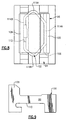
- Each lock assembly 96 generally includes a lock body 100 and a retaining wire 102 ( Figure 7 ). In one non-limiting embodiment, two lock assemblies 96 are arranged 180 degrees apart, however, any number of lock assemblies 96 may alternatively be utilized. The lock assembly 96 is retained in place during assembly and disassembly by the retaining wire 102 that is preassembled to the lock body 100 and engages the circumferentially intermittent slot structure 94 ( Figure 8 ).
- the lock assembly 96 reduces the cost of anti-rotation features such as the annular spacer 98 and integral milled features in that the lock assembly 96 utilizes scallops 93 ( Figure 6 ) formed between the cover plate stops 92. That is, the lock assembly 96 is readily inserted past the scallop 93.
- the lock body 100 is generally rectilinear in shape with rounded edges 106 to smoothly interface with the circumferentially intermittent slot structure 94.
- a lock tab 108 extends from the lock body 100 to axially trap the lock assembly 96 between the radial tab 88 and the annular spacer 98.
- An undercut slot 110 ( Figure 9 ) is located opposite the lock tab to receive the retaining wire 102 which is a polygonal shape.
- the retaining wire 102 includes a break 112 which permits flexibility during insertion and removal from the circumferentially intermittent slot structure 94 as well as installation into the undercut slot.
- the shape of the retaining wire 102 generally includes a opposed linear segments 114A, 114B of which the linear segment 114B includes the break 112 to form an interrupted somewhat elongated hexagonal shape. Rounded vertices 116A, 116B between the opposed linear segments 114A, 114B are readily captured between the circumferentially intermittent slot structure 94 to further facilitate intermediate assembly and disassembly through the snap-in interaction.
Landscapes
- Engineering & Computer Science (AREA)
- Mechanical Engineering (AREA)
- General Engineering & Computer Science (AREA)
- Structures Of Non-Positive Displacement Pumps (AREA)
- Turbine Rotor Nozzle Sealing (AREA)
- Braking Arrangements (AREA)
Claims (15)
- Ensemble à disque rotor pour un moteur à turbine à gaz, comprenant :un disque rotor (56) défini autour d'un axe de rotation, ledit disque rotor (56) possédant une structure à fente intermittente de façon circonférentielle (94) qui s'étend radialement vers l'extérieur par rapport audit axe de rotation ;un composant (52) défini autour dudit axe de rotation, ledit composant (52) possédant une multiplicité de languettes radiales (88) qui s'étendent radialement vers l'intérieur relativement audit axe de rotation, ladite multiplicité de languettes radiales (88) pouvant entrer en prise avec ladite structure à fente intermittente de façon circonférentielle (94) ; etun ensemble à verrouillage (96) en prise avec au moins une ouverture formée par ladite structure à fente intermittente de façon circonférentielle (94) pour fournir une interface anti-rotation pour ledit composant (52),l'ensemble à disque rotor étant caractérisé en ce que :ledit ensemble à verrouillage (96) comprend un fil métallique de retenue qui définit une forme polygonale, ledit fil métallique de retenue (102) étant en prise avec au moins une ouverture formée par ladite structure à fente intermittente de façon circonférentielle (94) pour fournir une interface anti-rotation pour ledit composant (52).
- Ensemble à disque rotor selon la revendication 1, dans lequel ledit composant (52) est un bouclier thermique.
- Ensemble à disque rotor selon la revendication 2, dans lequel ledit bouclier thermique (52) sépare une cavité diamétrale extérieure relativement plus chaude (80) d'une cavité diamétrale intérieure relativement plus froide (82).
- Ensemble à disque rotor selon la revendication 2 ou 3, dans lequel ledit bouclier thermique (52) couvre une interface (84).
- Ensemble à disque rotor selon la revendication 4, dans lequel ladite interface (84) est une interface cannelée entre une turbine à haute pression (46) et un compresseur à haute pression (44).
- Ensemble à disque rotor selon une quelconque revendication précédente, dans lequel ladite structure à fente intermittente de façon circonférentielle (94) s'étend radialement vers l'extérieur à partir d'une extension cylindrique (56C) dudit disque rotor (56).
- Ensemble à disque rotor selon une quelconque revendication précédente, dans lequel le disque rotor (56) est un disque rotor de turbine.
- Ensemble à rotor selon l'une quelconque revendication précédentes, dans lequel l'ensemble à verrouillage (96) comprend :un corps de verrouillage (100) avec une fente dégagée (110) ; etledit fil métallique de retenue (102) peut entrer en prise à l'intérieur de ladite fente dégagée (110).
- Ensemble à rotor selon la revendication 8, dans lequel ledit fil métallique de retenue (102) définit une forme hexagonale allongée.
- Ensemble à rotor selon la revendication 8 ou 9, dans lequel ledit fil métallique de retenue (102) inclut des segments linéaires opposés (114A, 114B), dont un inclut une rupture (112).
- Ensemble à rotor selon la revendication 10, dans lequel ledit fil métallique de retenue (102) inclut des sommets arrondis (116A, 116B) entre lesdits segments linéaires opposés (114A, 114B).
- Procédé pour assembler un ensemble à disque, comprenant :le positionnement d'une plaque couvercle (54) de façon adjacente à un disque rotor (56) le long d'un axe de rotation ;le positionnement axial d'un bouclier thermique (52) possédant une multiplicité de languettes radiales (88) qui s'étendent radialement vers l'intérieur relativement à l'axe de rotation, la multiplicité de languettes radiales (88) étant axialement alignées avec des ouvertures définies par une structure à fente intermittente de façon circonférentielle (94) sur le disque rotor (56) ; etla mise en prise d'un ensemble à verrouillage (96) avec la structure à fente intermittente de façon circonférentielle (94) pour fournir une interface anti-rotation pour le bouclier thermique (52) ; le procédé étant caractérisé en ce qu'il comprend :la rotation du bouclier thermique (52) pour aligner radialement la multiplicité de languettes radiales (88) avec la structure à fente intermittente de façon circonférentielle (94) pour retenir axialement la plaque couvercle (54) sur le disque rotor (56) ; etla mise en prise d'un fil métallique de retenue (102) d'un ensemble à verrouillage (96) avec la structure à fente intermittente de façon circonférentielle (94) pour fournir une interface anti-rotation pour le bouclier thermique (52), ledit fil métallique de retenue présentant une forme polygonale.
- Procédé selon la revendication 12, comprenant en outre l'encliquetage du fil métallique de retenue (102) de l'ensemble à verrouillage (96) dans la structure à fente intermittente de façon circonférentielle (94).
- Procédé selon la revendication 12 ou 13, comprenant en outre la couverture d'une interface (84) avec le bouclier thermique (52).
- Procédé selon la revendication 14, comprenant en outre la couverture d'une interface cannelée (84), entre une turbine à haute pression (46) et un compresseur à haute pression (44), avec le bouclier thermique (52).
Applications Claiming Priority (1)
| Application Number | Priority Date | Filing Date | Title |
|---|---|---|---|
| US13/053,134 US8840375B2 (en) | 2011-03-21 | 2011-03-21 | Component lock for a gas turbine engine |
Publications (3)
| Publication Number | Publication Date |
|---|---|
| EP2503098A2 EP2503098A2 (fr) | 2012-09-26 |
| EP2503098A3 EP2503098A3 (fr) | 2015-02-25 |
| EP2503098B1 true EP2503098B1 (fr) | 2016-05-11 |
Family
ID=45888011
Family Applications (1)
| Application Number | Title | Priority Date | Filing Date |
|---|---|---|---|
| EP12160419.3A Active EP2503098B1 (fr) | 2011-03-21 | 2012-03-20 | Ensemble de disque de rotor et ensemble de blocage à cet effet |
Country Status (2)
| Country | Link |
|---|---|
| US (1) | US8840375B2 (fr) |
| EP (1) | EP2503098B1 (fr) |
Families Citing this family (29)
| Publication number | Priority date | Publication date | Assignee | Title |
|---|---|---|---|---|
| FR2985766B1 (fr) * | 2012-01-16 | 2016-07-22 | Snecma | Agencement pour le guidage de l'ecoulement d'un liquide par rapport au rotor d'une turbomachine |
| US9303521B2 (en) * | 2012-09-27 | 2016-04-05 | United Technologies Corporation | Interstage coverplate assembly for arranging between adjacent rotor stages of a rotor assembly |
| US9297422B2 (en) * | 2012-10-25 | 2016-03-29 | Pratt & Whitney Canada Corp. | Coupling element for torque transmission in a gas turbine engine |
| EP3693543A1 (fr) | 2013-04-18 | 2020-08-12 | United Technologies Corporation | Amortisseur de minidisque de turbine pour turbine à gaz |
| EP2808490A1 (fr) * | 2013-05-29 | 2014-12-03 | Alstom Technology Ltd | Aube de turbine avec pion de blocage |
| US9869190B2 (en) | 2014-05-30 | 2018-01-16 | General Electric Company | Variable-pitch rotor with remote counterweights |
| FR3026430B1 (fr) * | 2014-09-29 | 2020-07-10 | Safran Aircraft Engines | Roue de turbine dans une turbomachine |
| US10072510B2 (en) | 2014-11-21 | 2018-09-11 | General Electric Company | Variable pitch fan for gas turbine engine and method of assembling the same |
| US10018063B2 (en) * | 2015-06-10 | 2018-07-10 | United Technologies Corporation | Anti-rotation knife edge seals and gas turbine engines including the same |
| US10100653B2 (en) | 2015-10-08 | 2018-10-16 | General Electric Company | Variable pitch fan blade retention system |
| HRP20211470T1 (hr) | 2015-12-28 | 2021-12-24 | Lydall, Inc. | Termički štit sa karakteristikom zadržavanja |
| US10145249B2 (en) | 2016-02-23 | 2018-12-04 | Mechanical Dynamics & Analysis Llc | Turbine bucket lockwire anti-rotation device for gas turbine engine |
| US10329929B2 (en) * | 2016-03-15 | 2019-06-25 | United Technologies Corporation | Retaining ring axially loaded against segmented disc surface |
| US10323519B2 (en) * | 2016-06-23 | 2019-06-18 | United Technologies Corporation | Gas turbine engine having a turbine rotor with torque transfer and balance features |
| US10344622B2 (en) | 2016-07-22 | 2019-07-09 | United Technologies Corporation | Assembly with mistake proof bayoneted lug |
| US10968744B2 (en) | 2017-05-04 | 2021-04-06 | Rolls-Royce Corporation | Turbine rotor assembly having a retaining collar for a bayonet mount |
| US10774678B2 (en) | 2017-05-04 | 2020-09-15 | Rolls-Royce Corporation | Turbine assembly with auxiliary wheel |
| US10865646B2 (en) * | 2017-05-04 | 2020-12-15 | Rolls-Royce Corporation | Turbine assembly with auxiliary wheel |
| CA2998258A1 (fr) * | 2017-05-04 | 2018-11-04 | Rolls-Royce Corporation | Assemblage de turbine a roue auxiliaire |
| US10385874B2 (en) | 2017-05-08 | 2019-08-20 | Solar Turbines Incorporated | Pin to reduce relative rotational movement of disk and spacer of turbine engine |
| FR3073001B1 (fr) * | 2017-10-26 | 2021-07-23 | Safran Aircraft Engines | Ensemble pour disque de turbine |
| US11168565B2 (en) | 2018-08-28 | 2021-11-09 | Raytheon Technologies Corporation | Heat shield insert |
| FR3092861B1 (fr) * | 2019-02-18 | 2023-02-10 | Safran Aircraft Engines | Ensemble de turbomachine comportant un taquet sur un jonc d'etancheite |
| US11371375B2 (en) | 2019-08-19 | 2022-06-28 | Raytheon Technologies Corporation | Heatshield with damper member |
| US11414993B1 (en) * | 2021-03-23 | 2022-08-16 | Pratt & Whitney Canada Corp. | Retaining assembly with anti-rotation feature |
| US11674435B2 (en) | 2021-06-29 | 2023-06-13 | General Electric Company | Levered counterweight feathering system |
| US11795964B2 (en) | 2021-07-16 | 2023-10-24 | General Electric Company | Levered counterweight feathering system |
| US12601271B2 (en) | 2022-10-21 | 2026-04-14 | General Electric Company | Variable pitch fan of a gas turbine engine |
| DE102024105064A1 (de) * | 2024-02-22 | 2025-08-28 | MTU Aero Engines AG | Spannverbundbaugruppe |
Family Cites Families (105)
| Publication number | Priority date | Publication date | Assignee | Title |
|---|---|---|---|---|
| FR966804A (fr) | 1947-03-11 | 1950-10-19 | Rolls Royce | Perfectionnements aux moteurs à turbine à gaz |
| US2788951A (en) | 1951-02-15 | 1957-04-16 | Power Jets Res & Dev Ltd | Cooling of turbine rotors |
| DE1070880B (de) | 1956-12-19 | 1959-12-10 | Rolls-Royce Limited, Derby (Großbritannien) | Gasturbinenaggregat mit Turboverdichter |
| US2988325A (en) | 1957-07-18 | 1961-06-13 | Rolls Royce | Rotary fluid machine with means supplying fluid to rotor blade passages |
| US3451653A (en) * | 1967-03-22 | 1969-06-24 | Gen Electric | Turbomachinery rotors |
| US3952391A (en) * | 1974-07-22 | 1976-04-27 | General Motors Corporation | Turbine blade with configured stalk |
| US4004860A (en) | 1974-07-22 | 1977-01-25 | General Motors Corporation | Turbine blade with configured stalk |
| GB1479332A (en) | 1974-11-06 | 1977-07-13 | Rolls Royce | Means for retaining blades to a disc or like structure |
| US3982852A (en) | 1974-11-29 | 1976-09-28 | General Electric Company | Bore vane assembly for use with turbine discs having bore entry cooling |
| US3997962A (en) | 1975-06-06 | 1976-12-21 | United Technologies Corporation | Method and tool for removing turbine from gas turbine twin spool engine |
| CA1040535A (fr) | 1976-02-09 | 1978-10-17 | Westinghouse Electric Corporation | Deflecteur orientable et son support dans une tuyere de turbine a gaz |
| DE2633291C3 (de) | 1976-07-23 | 1981-05-14 | Kraftwerk Union AG, 4330 Mülheim | Gasturbinenanlage mit Kühlung durch zwei unabhängige Kühlluftströme |
| GB2042652B (en) | 1979-02-21 | 1983-07-20 | Rolls Royce | Joint making packing |
| US4480958A (en) | 1983-02-09 | 1984-11-06 | The United States Of America As Represented By The Secretary Of The Air Force | High pressure turbine rotor two-piece blade retainer |
| US4576547A (en) | 1983-11-03 | 1986-03-18 | United Technologies Corporation | Active clearance control |
| US4582467A (en) | 1983-12-22 | 1986-04-15 | United Technologies Corporation | Two stage rotor assembly with improved coolant flow |
| US4669959A (en) | 1984-07-23 | 1987-06-02 | United Technologies Corporation | Breach lock anti-rotation key |
| US4645416A (en) | 1984-11-01 | 1987-02-24 | United Technologies Corporation | Valve and manifold for compressor bore heating |
| US4664599A (en) | 1985-05-01 | 1987-05-12 | United Technologies Corporation | Two stage turbine rotor assembly |
| DE222679T1 (de) | 1985-11-04 | 1987-10-15 | United Technologies Corp., Hartford, Conn. | Seitenplatte fuer eine turbinenscheibe. |
| US4882902A (en) | 1986-04-30 | 1989-11-28 | General Electric Company | Turbine cooling air transferring apparatus |
| US4737076A (en) * | 1986-10-20 | 1988-04-12 | United Technologies Corporation | Means for maintaining concentricity of rotating components |
| FR2607866B1 (fr) | 1986-12-03 | 1991-04-12 | Snecma | Axes de fixation de rotors de turbomachine, procede de montage et rotors ainsi montes |
| GB8705216D0 (en) | 1987-03-06 | 1987-04-08 | Rolls Royce Plc | Rotor assembly |
| US4820116A (en) | 1987-09-18 | 1989-04-11 | United Technologies Corporation | Turbine cooling for gas turbine engine |
| US4822244A (en) | 1987-10-15 | 1989-04-18 | United Technologies Corporation | Tobi |
| JP2756117B2 (ja) | 1987-11-25 | 1998-05-25 | 株式会社日立製作所 | ガスタービンロータ |
| US4846628A (en) * | 1988-12-23 | 1989-07-11 | United Technologies Corporation | Rotor assembly for a turbomachine |
| US4890981A (en) | 1988-12-30 | 1990-01-02 | General Electric Company | Boltless rotor blade retainer |
| DE59107419D1 (de) | 1990-06-27 | 1996-03-28 | Ciba Geigy Ag | Azofarbstoffe mit 2-Alkylamino-3-cyan-4,6-diaminopyridinen als Kupplungskomponenten |
| FR2663997B1 (fr) | 1990-06-27 | 1993-12-24 | Snecma | Dispositif de fixation d'une couronne de revolution sur un disque de turbomachine. |
| US5151013A (en) * | 1990-12-27 | 1992-09-29 | United Technologies Corporation | Blade lock for a rotor disk and rotor blade assembly |
| US5288210A (en) * | 1991-10-30 | 1994-02-22 | General Electric Company | Turbine disk attachment system |
| US5275534A (en) | 1991-10-30 | 1994-01-04 | General Electric Company | Turbine disk forward seal assembly |
| US5472313A (en) | 1991-10-30 | 1995-12-05 | General Electric Company | Turbine disk cooling system |
| US5232335A (en) | 1991-10-30 | 1993-08-03 | General Electric Company | Interstage thermal shield retention system |
| US5215440A (en) * | 1991-10-30 | 1993-06-01 | General Electric Company | Interstage thermal shield with asymmetric bore |
| US5236302A (en) * | 1991-10-30 | 1993-08-17 | General Electric Company | Turbine disk interstage seal system |
| US5320488A (en) | 1993-01-21 | 1994-06-14 | General Electric Company | Turbine disk interstage seal anti-rotation system |
| US5318405A (en) * | 1993-03-17 | 1994-06-07 | General Electric Company | Turbine disk interstage seal anti-rotation key through disk dovetail slot |
| US5338154A (en) * | 1993-03-17 | 1994-08-16 | General Electric Company | Turbine disk interstage seal axial retaining ring |
| US5537814A (en) * | 1994-09-28 | 1996-07-23 | General Electric Company | High pressure gas generator rotor tie rod system for gas turbine engine |
| US5601741A (en) | 1994-11-18 | 1997-02-11 | Illinois Tool Works, Inc. | Method and apparatus for receiving a universal input voltage in a welding power source |
| KR100389990B1 (ko) | 1995-04-06 | 2003-11-17 | 가부시끼가이샤 히다치 세이사꾸쇼 | 가스터빈 |
| GB9517369D0 (en) * | 1995-08-24 | 1995-10-25 | Rolls Royce Plc | Bladed rotor |
| FR2744761B1 (fr) | 1996-02-08 | 1998-03-13 | Snecma | Disque labyrinthe avec raidisseur incorpore pour rotor de turbomachine |
| GB2317652B (en) | 1996-09-26 | 2000-05-17 | Rolls Royce Plc | Seal arrangement |
| US6393829B2 (en) | 1996-11-29 | 2002-05-28 | Hitachi, Ltd. | Coolant recovery type gas turbine |
| US5862666A (en) | 1996-12-23 | 1999-01-26 | Pratt & Whitney Canada Inc. | Turbine engine having improved thrust bearing load control |
| DE19654471B4 (de) * | 1996-12-27 | 2006-05-24 | Alstom | Rotor einer Strömungsmaschine |
| GB2332024B (en) | 1997-12-03 | 2000-12-13 | Rolls Royce Plc | Rotary assembly |
| US6077035A (en) | 1998-03-27 | 2000-06-20 | Pratt & Whitney Canada Corp. | Deflector for controlling entry of cooling air leakage into the gaspath of a gas turbine engine |
| US6035627A (en) | 1998-04-21 | 2000-03-14 | Pratt & Whitney Canada Inc. | Turbine engine with cooled P3 air to impeller rear cavity |
| US6053697A (en) | 1998-06-26 | 2000-04-25 | General Electric Company | Trilobe mounting with anti-rotation apparatus for an air duct in a gas turbine rotor |
| FR2782539B1 (fr) | 1998-08-20 | 2000-10-06 | Snecma | Turbomachine comportant un dispositif de fourniture de gaz pressurise |
| US6224329B1 (en) | 1999-01-07 | 2001-05-01 | Siemens Westinghouse Power Corporation | Method of cooling a combustion turbine |
| US6227801B1 (en) | 1999-04-27 | 2001-05-08 | Pratt & Whitney Canada Corp. | Turbine engine having improved high pressure turbine cooling |
| US6283712B1 (en) | 1999-09-07 | 2001-09-04 | General Electric Company | Cooling air supply through bolted flange assembly |
| GB9925261D0 (en) * | 1999-10-27 | 1999-12-29 | Rolls Royce Plc | Locking devices |
| US6375429B1 (en) | 2001-02-05 | 2002-04-23 | General Electric Company | Turbomachine blade-to-rotor sealing arrangement |
| FR2825413B1 (fr) | 2001-05-31 | 2003-09-05 | Snecma Moteurs | Dispositif de prelevement d'air par ecoulement centripete |
| US6575703B2 (en) | 2001-07-20 | 2003-06-10 | General Electric Company | Turbine disk side plate |
| US6901821B2 (en) * | 2001-11-20 | 2005-06-07 | United Technologies Corporation | Stator damper anti-rotation assembly |
| US6877950B2 (en) | 2001-11-29 | 2005-04-12 | Pratt & Whitney Canada Corp. | Method and device for minimizing oil consumption in a gas turbine engine |
| DE10159670A1 (de) | 2001-12-05 | 2003-06-18 | Rolls Royce Deutschland | Wirbelgleichrichter im Hochdruckverdichter einer Gasturbine |
| US6749400B2 (en) | 2002-08-29 | 2004-06-15 | General Electric Company | Gas turbine engine disk rim with axially cutback and circumferentially skewed cooling air slots |
| FR2850130B1 (fr) | 2003-01-16 | 2006-01-20 | Snecma Moteurs | Dispositif pour retenir un flasque annulaire contre une face radiale d'un disque |
| US6899520B2 (en) | 2003-09-02 | 2005-05-31 | General Electric Company | Methods and apparatus to reduce seal rubbing within gas turbine engines |
| US6910852B2 (en) | 2003-09-05 | 2005-06-28 | General Electric Company | Methods and apparatus for cooling gas turbine engine rotor assemblies |
| US6960060B2 (en) | 2003-11-20 | 2005-11-01 | General Electric Company | Dual coolant turbine blade |
| US6981841B2 (en) | 2003-11-20 | 2006-01-03 | General Electric Company | Triple circuit turbine cooling |
| GB2410984B (en) * | 2004-02-14 | 2006-03-08 | Rolls Royce Plc | Securing assembly |
| US7059831B2 (en) | 2004-04-15 | 2006-06-13 | United Technologies Corporation | Turbine engine disk spacers |
| GB0413652D0 (en) * | 2004-06-18 | 2004-07-21 | Rolls Royce Plc | Gas turbine engine structure |
| FR2873161B1 (fr) * | 2004-07-15 | 2008-10-10 | Snecma Moteurs Sa | Ensemble comprenant un arbre rotatif et un palier a roulement |
| US7229247B2 (en) | 2004-08-27 | 2007-06-12 | Pratt & Whitney Canada Corp. | Duct with integrated baffle |
| US7229249B2 (en) | 2004-08-27 | 2007-06-12 | Pratt & Whitney Canada Corp. | Lightweight annular interturbine duct |
| GB0423363D0 (en) * | 2004-10-21 | 2004-11-24 | Rolls Royce Plc | Rotor assembly retaining apparatus |
| US7179049B2 (en) | 2004-12-10 | 2007-02-20 | Pratt & Whitney Canada Corp. | Gas turbine gas path contour |
| US7520718B2 (en) | 2005-07-18 | 2009-04-21 | Siemens Energy, Inc. | Seal and locking plate for turbine rotor assembly between turbine blade and turbine vane |
| FR2888897B1 (fr) * | 2005-07-21 | 2007-10-19 | Snecma | Dispositif d'amortissement des vibrations d'un anneau de retention axiale des aubes de soufflante d'une turbomachine |
| FR2889565B1 (fr) | 2005-08-03 | 2012-05-18 | Snecma | Compresseur a prelevement d'air centripete |
| US7344354B2 (en) | 2005-09-08 | 2008-03-18 | General Electric Company | Methods and apparatus for operating gas turbine engines |
| US7331763B2 (en) | 2005-12-20 | 2008-02-19 | General Electric Company | Turbine disk |
| US7458774B2 (en) | 2005-12-20 | 2008-12-02 | General Electric Company | High pressure turbine disk hub with curved hub surface and method |
| US7578656B2 (en) | 2005-12-20 | 2009-08-25 | General Electric Company | High pressure turbine disk hub with reduced axial stress and method |
| JP2007247406A (ja) * | 2006-03-13 | 2007-09-27 | Ihi Corp | ファンブレードの保持構造 |
| US7743613B2 (en) | 2006-11-10 | 2010-06-29 | General Electric Company | Compound turbine cooled engine |
| US8267664B2 (en) * | 2008-04-04 | 2012-09-18 | General Electric Company | Axial compressor blade retention |
| GB0809759D0 (en) | 2008-05-30 | 2008-07-09 | Rolls Royce Plc | Gas turbine engine |
| US8240987B2 (en) | 2008-08-15 | 2012-08-14 | United Technologies Corp. | Gas turbine engine systems involving baffle assemblies |
| GB2463036B (en) * | 2008-08-29 | 2011-04-20 | Rolls Royce Plc | A blade arrangement |
| US8215902B2 (en) | 2008-10-15 | 2012-07-10 | United Technologies Corporation | Scalable high pressure compressor variable vane actuation arm |
| US8287242B2 (en) | 2008-11-17 | 2012-10-16 | United Technologies Corporation | Turbine engine rotor hub |
| US20100150711A1 (en) | 2008-12-12 | 2010-06-17 | United Technologies Corporation | Apparatus and method for preventing cracking of turbine engine cases |
| US8206119B2 (en) * | 2009-02-05 | 2012-06-26 | General Electric Company | Turbine coverplate systems |
| FR2945329B1 (fr) * | 2009-05-06 | 2011-06-03 | Snecma | Rotor de soufflante d'un turboracteur d'avion |
| US8459954B2 (en) * | 2010-01-19 | 2013-06-11 | United Technologies Corporation | Torsional flexing energy absorbing blade lock |
| FR2955889B1 (fr) * | 2010-01-29 | 2012-11-16 | Snecma | Moyen de blocage d'un flasque d'etancheite sur un disque de turbine |
| US8496439B2 (en) * | 2010-03-17 | 2013-07-30 | Siemens Energy, Inc. | Turbomachine blade locking structure including shape memory alloy |
| US8870544B2 (en) * | 2010-07-29 | 2014-10-28 | United Technologies Corporation | Rotor cover plate retention method |
| US8491267B2 (en) * | 2010-08-27 | 2013-07-23 | Pratt & Whitney Canada Corp. | Retaining ring arrangement for a rotary assembly |
| US8608436B2 (en) * | 2010-08-31 | 2013-12-17 | General Electric Company | Tapered collet connection of rotor components |
| GB2477825B (en) * | 2010-09-23 | 2015-04-01 | Rolls Royce Plc | Anti fret liner assembly |
| US8753090B2 (en) * | 2010-11-24 | 2014-06-17 | Rolls-Royce Corporation | Bladed disk assembly |
-
2011
- 2011-03-21 US US13/053,134 patent/US8840375B2/en active Active
-
2012
- 2012-03-20 EP EP12160419.3A patent/EP2503098B1/fr active Active
Also Published As
| Publication number | Publication date |
|---|---|
| EP2503098A2 (fr) | 2012-09-26 |
| US20120244004A1 (en) | 2012-09-27 |
| EP2503098A3 (fr) | 2015-02-25 |
| US8840375B2 (en) | 2014-09-23 |
Similar Documents
| Publication | Publication Date | Title |
|---|---|---|
| EP2503098B1 (fr) | Ensemble de disque de rotor et ensemble de blocage à cet effet | |
| EP2474707B1 (fr) | Protection thermique multifonction pour moteur de turbine à gaz | |
| EP2474708B1 (fr) | Agencement de joint et procédé associé d'assemblage | |
| EP2920428B1 (fr) | Verrouillage de support | |
| EP2900933B1 (fr) | Joint à air intérieur annulaire complet avec écrou de verrouillage | |
| US10989111B2 (en) | Turbine minidisk bumper for gas turbine engine | |
| EP2984290B1 (fr) | Rotor à aubage intégré | |
| EP2984292B1 (fr) | Plate-forme à aubes de stator avec brides | |
| US8840374B2 (en) | Adaptor assembly for coupling turbine blades to rotor disks | |
| EP3103966B1 (fr) | Joints de bord tranchant anti-rotation et moteurs à turbine à gaz le comprenant | |
| US20150218966A1 (en) | Gas turbine engine fan spacer platform attachments | |
| EP2984303B1 (fr) | Couvercle pour un ensemble rotor d'une turbine à gaz | |
| EP3112615B1 (fr) | Section de compresseur avec maintien particulier d'une aube de distributeur | |
| EP2943658B1 (fr) | Dispositif anti-rotation de stator | |
| EP3795869A1 (fr) | Ensemble d'étanchéité doté d'un dispositif de verrouillage anti-rotation | |
| US12049904B2 (en) | Tandem blade rotor disk | |
| EP2898189B1 (fr) | Carter de compresseur à haute pression à étages multiples | |
| EP3011155B1 (fr) | Bouclier thermique | |
| US9835032B2 (en) | Disk lug cooling flow trenches | |
| EP3290640B1 (fr) | Moteur à turbine à gaz avec un ensemble de retenue avec languettes et bague de retenue | |
| EP3453836B1 (fr) | Support d'aube de stator présentant des caractéristiques anti-rotation |
Legal Events
| Date | Code | Title | Description |
|---|---|---|---|
| PUAI | Public reference made under article 153(3) epc to a published international application that has entered the european phase |
Free format text: ORIGINAL CODE: 0009012 |
|
| AK | Designated contracting states |
Kind code of ref document: A2 Designated state(s): AL AT BE BG CH CY CZ DE DK EE ES FI FR GB GR HR HU IE IS IT LI LT LU LV MC MK MT NL NO PL PT RO RS SE SI SK SM TR |
|
| AX | Request for extension of the european patent |
Extension state: BA ME |
|
| PUAL | Search report despatched |
Free format text: ORIGINAL CODE: 0009013 |
|
| AK | Designated contracting states |
Kind code of ref document: A3 Designated state(s): AL AT BE BG CH CY CZ DE DK EE ES FI FR GB GR HR HU IE IS IT LI LT LU LV MC MK MT NL NO PL PT RO RS SE SI SK SM TR |
|
| AX | Request for extension of the european patent |
Extension state: BA ME |
|
| RIC1 | Information provided on ipc code assigned before grant |
Ipc: F01D 5/08 20060101ALI20150120BHEP Ipc: F01D 5/06 20060101AFI20150120BHEP Ipc: F01D 5/30 20060101ALI20150120BHEP |
|
| 17P | Request for examination filed |
Effective date: 20150825 |
|
| RBV | Designated contracting states (corrected) |
Designated state(s): AL AT BE BG CH CY CZ DE DK EE ES FI FR GB GR HR HU IE IS IT LI LT LU LV MC MK MT NL NO PL PT RO RS SE SI SK SM TR |
|
| GRAP | Despatch of communication of intention to grant a patent |
Free format text: ORIGINAL CODE: EPIDOSNIGR1 |
|
| INTG | Intention to grant announced |
Effective date: 20151211 |
|
| GRAS | Grant fee paid |
Free format text: ORIGINAL CODE: EPIDOSNIGR3 |
|
| GRAA | (expected) grant |
Free format text: ORIGINAL CODE: 0009210 |
|
| AK | Designated contracting states |
Kind code of ref document: B1 Designated state(s): AL AT BE BG CH CY CZ DE DK EE ES FI FR GB GR HR HU IE IS IT LI LT LU LV MC MK MT NL NO PL PT RO RS SE SI SK SM TR |
|
| REG | Reference to a national code |
Ref country code: GB Ref legal event code: FG4D |
|
| REG | Reference to a national code |
Ref country code: CH Ref legal event code: EP |
|
| REG | Reference to a national code |
Ref country code: AT Ref legal event code: REF Ref document number: 798845 Country of ref document: AT Kind code of ref document: T Effective date: 20160515 |
|
| REG | Reference to a national code |
Ref country code: IE Ref legal event code: FG4D |
|
| REG | Reference to a national code |
Ref country code: DE Ref legal event code: R096 Ref document number: 602012018252 Country of ref document: DE |
|
| REG | Reference to a national code |
Ref country code: LT Ref legal event code: MG4D |
|
| REG | Reference to a national code |
Ref country code: NL Ref legal event code: MP Effective date: 20160511 |
|
| REG | Reference to a national code |
Ref country code: CH Ref legal event code: PCOW Free format text: NEW ADDRESS: 10 FARM SPRINGS RD., FARMINGTON, CT 06032 (US) |
|
| RAP2 | Party data changed (patent owner data changed or rights of a patent transferred) |
Owner name: UNITED TECHNOLOGIES CORPORATION |
|
| PG25 | Lapsed in a contracting state [announced via postgrant information from national office to epo] |
Ref country code: LT Free format text: LAPSE BECAUSE OF FAILURE TO SUBMIT A TRANSLATION OF THE DESCRIPTION OR TO PAY THE FEE WITHIN THE PRESCRIBED TIME-LIMIT Effective date: 20160511 Ref country code: FI Free format text: LAPSE BECAUSE OF FAILURE TO SUBMIT A TRANSLATION OF THE DESCRIPTION OR TO PAY THE FEE WITHIN THE PRESCRIBED TIME-LIMIT Effective date: 20160511 Ref country code: NL Free format text: LAPSE BECAUSE OF FAILURE TO SUBMIT A TRANSLATION OF THE DESCRIPTION OR TO PAY THE FEE WITHIN THE PRESCRIBED TIME-LIMIT Effective date: 20160511 Ref country code: NO Free format text: LAPSE BECAUSE OF FAILURE TO SUBMIT A TRANSLATION OF THE DESCRIPTION OR TO PAY THE FEE WITHIN THE PRESCRIBED TIME-LIMIT Effective date: 20160811 |
|
| REG | Reference to a national code |
Ref country code: AT Ref legal event code: MK05 Ref document number: 798845 Country of ref document: AT Kind code of ref document: T Effective date: 20160511 |
|
| PG25 | Lapsed in a contracting state [announced via postgrant information from national office to epo] |
Ref country code: GR Free format text: LAPSE BECAUSE OF FAILURE TO SUBMIT A TRANSLATION OF THE DESCRIPTION OR TO PAY THE FEE WITHIN THE PRESCRIBED TIME-LIMIT Effective date: 20160812 Ref country code: HR Free format text: LAPSE BECAUSE OF FAILURE TO SUBMIT A TRANSLATION OF THE DESCRIPTION OR TO PAY THE FEE WITHIN THE PRESCRIBED TIME-LIMIT Effective date: 20160511 Ref country code: ES Free format text: LAPSE BECAUSE OF FAILURE TO SUBMIT A TRANSLATION OF THE DESCRIPTION OR TO PAY THE FEE WITHIN THE PRESCRIBED TIME-LIMIT Effective date: 20160511 Ref country code: RS Free format text: LAPSE BECAUSE OF FAILURE TO SUBMIT A TRANSLATION OF THE DESCRIPTION OR TO PAY THE FEE WITHIN THE PRESCRIBED TIME-LIMIT Effective date: 20160511 Ref country code: PT Free format text: LAPSE BECAUSE OF FAILURE TO SUBMIT A TRANSLATION OF THE DESCRIPTION OR TO PAY THE FEE WITHIN THE PRESCRIBED TIME-LIMIT Effective date: 20160912 Ref country code: LV Free format text: LAPSE BECAUSE OF FAILURE TO SUBMIT A TRANSLATION OF THE DESCRIPTION OR TO PAY THE FEE WITHIN THE PRESCRIBED TIME-LIMIT Effective date: 20160511 Ref country code: SE Free format text: LAPSE BECAUSE OF FAILURE TO SUBMIT A TRANSLATION OF THE DESCRIPTION OR TO PAY THE FEE WITHIN THE PRESCRIBED TIME-LIMIT Effective date: 20160511 |
|
| PG25 | Lapsed in a contracting state [announced via postgrant information from national office to epo] |
Ref country code: IT Free format text: LAPSE BECAUSE OF FAILURE TO SUBMIT A TRANSLATION OF THE DESCRIPTION OR TO PAY THE FEE WITHIN THE PRESCRIBED TIME-LIMIT Effective date: 20160511 |
|
| PG25 | Lapsed in a contracting state [announced via postgrant information from national office to epo] |
Ref country code: SK Free format text: LAPSE BECAUSE OF FAILURE TO SUBMIT A TRANSLATION OF THE DESCRIPTION OR TO PAY THE FEE WITHIN THE PRESCRIBED TIME-LIMIT Effective date: 20160511 Ref country code: DK Free format text: LAPSE BECAUSE OF FAILURE TO SUBMIT A TRANSLATION OF THE DESCRIPTION OR TO PAY THE FEE WITHIN THE PRESCRIBED TIME-LIMIT Effective date: 20160511 Ref country code: RO Free format text: LAPSE BECAUSE OF FAILURE TO SUBMIT A TRANSLATION OF THE DESCRIPTION OR TO PAY THE FEE WITHIN THE PRESCRIBED TIME-LIMIT Effective date: 20160511 Ref country code: CZ Free format text: LAPSE BECAUSE OF FAILURE TO SUBMIT A TRANSLATION OF THE DESCRIPTION OR TO PAY THE FEE WITHIN THE PRESCRIBED TIME-LIMIT Effective date: 20160511 Ref country code: EE Free format text: LAPSE BECAUSE OF FAILURE TO SUBMIT A TRANSLATION OF THE DESCRIPTION OR TO PAY THE FEE WITHIN THE PRESCRIBED TIME-LIMIT Effective date: 20160511 |
|
| REG | Reference to a national code |
Ref country code: DE Ref legal event code: R097 Ref document number: 602012018252 Country of ref document: DE |
|
| PG25 | Lapsed in a contracting state [announced via postgrant information from national office to epo] |
Ref country code: AT Free format text: LAPSE BECAUSE OF FAILURE TO SUBMIT A TRANSLATION OF THE DESCRIPTION OR TO PAY THE FEE WITHIN THE PRESCRIBED TIME-LIMIT Effective date: 20160511 Ref country code: SM Free format text: LAPSE BECAUSE OF FAILURE TO SUBMIT A TRANSLATION OF THE DESCRIPTION OR TO PAY THE FEE WITHIN THE PRESCRIBED TIME-LIMIT Effective date: 20160511 Ref country code: BE Free format text: LAPSE BECAUSE OF FAILURE TO SUBMIT A TRANSLATION OF THE DESCRIPTION OR TO PAY THE FEE WITHIN THE PRESCRIBED TIME-LIMIT Effective date: 20160511 Ref country code: PL Free format text: LAPSE BECAUSE OF FAILURE TO SUBMIT A TRANSLATION OF THE DESCRIPTION OR TO PAY THE FEE WITHIN THE PRESCRIBED TIME-LIMIT Effective date: 20160511 |
|
| PLBE | No opposition filed within time limit |
Free format text: ORIGINAL CODE: 0009261 |
|
| STAA | Information on the status of an ep patent application or granted ep patent |
Free format text: STATUS: NO OPPOSITION FILED WITHIN TIME LIMIT |
|
| 26N | No opposition filed |
Effective date: 20170214 |
|
| PG25 | Lapsed in a contracting state [announced via postgrant information from national office to epo] |
Ref country code: SI Free format text: LAPSE BECAUSE OF FAILURE TO SUBMIT A TRANSLATION OF THE DESCRIPTION OR TO PAY THE FEE WITHIN THE PRESCRIBED TIME-LIMIT Effective date: 20160511 |
|
| REG | Reference to a national code |
Ref country code: DE Ref legal event code: R082 Ref document number: 602012018252 Country of ref document: DE Representative=s name: SCHMITT-NILSON SCHRAUD WAIBEL WOHLFROM PATENTA, DE |
|
| REG | Reference to a national code |
Ref country code: DE Ref legal event code: R082 Ref document number: 602012018252 Country of ref document: DE Representative=s name: SCHMITT-NILSON SCHRAUD WAIBEL WOHLFROM PATENTA, DE Ref country code: DE Ref legal event code: R081 Ref document number: 602012018252 Country of ref document: DE Owner name: UNITED TECHNOLOGIES CORP. (N.D.GES.D. STAATES , US Free format text: FORMER OWNER: UNITED TECHNOLOGIES CORPORATION, HARTFORD, CONN., US |
|
| REG | Reference to a national code |
Ref country code: CH Ref legal event code: PL |
|
| PG25 | Lapsed in a contracting state [announced via postgrant information from national office to epo] |
Ref country code: MC Free format text: LAPSE BECAUSE OF FAILURE TO SUBMIT A TRANSLATION OF THE DESCRIPTION OR TO PAY THE FEE WITHIN THE PRESCRIBED TIME-LIMIT Effective date: 20160511 |
|
| REG | Reference to a national code |
Ref country code: IE Ref legal event code: MM4A |
|
| REG | Reference to a national code |
Ref country code: FR Ref legal event code: ST Effective date: 20171130 |
|
| PG25 | Lapsed in a contracting state [announced via postgrant information from national office to epo] |
Ref country code: FR Free format text: LAPSE BECAUSE OF NON-PAYMENT OF DUE FEES Effective date: 20170331 Ref country code: LU Free format text: LAPSE BECAUSE OF NON-PAYMENT OF DUE FEES Effective date: 20170320 |
|
| PG25 | Lapsed in a contracting state [announced via postgrant information from national office to epo] |
Ref country code: IE Free format text: LAPSE BECAUSE OF NON-PAYMENT OF DUE FEES Effective date: 20170320 Ref country code: LI Free format text: LAPSE BECAUSE OF NON-PAYMENT OF DUE FEES Effective date: 20170331 Ref country code: CH Free format text: LAPSE BECAUSE OF NON-PAYMENT OF DUE FEES Effective date: 20170331 |
|
| PG25 | Lapsed in a contracting state [announced via postgrant information from national office to epo] |
Ref country code: MT Free format text: LAPSE BECAUSE OF NON-PAYMENT OF DUE FEES Effective date: 20170320 |
|
| PG25 | Lapsed in a contracting state [announced via postgrant information from national office to epo] |
Ref country code: AL Free format text: LAPSE BECAUSE OF FAILURE TO SUBMIT A TRANSLATION OF THE DESCRIPTION OR TO PAY THE FEE WITHIN THE PRESCRIBED TIME-LIMIT Effective date: 20160511 |
|
| PG25 | Lapsed in a contracting state [announced via postgrant information from national office to epo] |
Ref country code: HU Free format text: LAPSE BECAUSE OF FAILURE TO SUBMIT A TRANSLATION OF THE DESCRIPTION OR TO PAY THE FEE WITHIN THE PRESCRIBED TIME-LIMIT; INVALID AB INITIO Effective date: 20120320 |
|
| PG25 | Lapsed in a contracting state [announced via postgrant information from national office to epo] |
Ref country code: BG Free format text: LAPSE BECAUSE OF FAILURE TO SUBMIT A TRANSLATION OF THE DESCRIPTION OR TO PAY THE FEE WITHIN THE PRESCRIBED TIME-LIMIT Effective date: 20160511 |
|
| PG25 | Lapsed in a contracting state [announced via postgrant information from national office to epo] |
Ref country code: CY Free format text: LAPSE BECAUSE OF NON-PAYMENT OF DUE FEES Effective date: 20160511 |
|
| PG25 | Lapsed in a contracting state [announced via postgrant information from national office to epo] |
Ref country code: MK Free format text: LAPSE BECAUSE OF FAILURE TO SUBMIT A TRANSLATION OF THE DESCRIPTION OR TO PAY THE FEE WITHIN THE PRESCRIBED TIME-LIMIT Effective date: 20160511 |
|
| PG25 | Lapsed in a contracting state [announced via postgrant information from national office to epo] |
Ref country code: TR Free format text: LAPSE BECAUSE OF FAILURE TO SUBMIT A TRANSLATION OF THE DESCRIPTION OR TO PAY THE FEE WITHIN THE PRESCRIBED TIME-LIMIT Effective date: 20160511 |
|
| PG25 | Lapsed in a contracting state [announced via postgrant information from national office to epo] |
Ref country code: IS Free format text: LAPSE BECAUSE OF FAILURE TO SUBMIT A TRANSLATION OF THE DESCRIPTION OR TO PAY THE FEE WITHIN THE PRESCRIBED TIME-LIMIT Effective date: 20160911 |
|
| REG | Reference to a national code |
Ref country code: DE Ref legal event code: R081 Ref document number: 602012018252 Country of ref document: DE Owner name: RAYTHEON TECHNOLOGIES CORPORATION (N.D.GES.D.S, US Free format text: FORMER OWNER: UNITED TECHNOLOGIES CORP. (N.D.GES.D. STAATES DELAWARE), FARMINGTON, CONN., US Ref country code: DE Ref legal event code: R081 Ref document number: 602012018252 Country of ref document: DE Owner name: RTX CORPORATION (N.D.GES.D. STAATES DELAWARE),, US Free format text: FORMER OWNER: UNITED TECHNOLOGIES CORP. (N.D.GES.D. STAATES DELAWARE), FARMINGTON, CONN., US |
|
| P01 | Opt-out of the competence of the unified patent court (upc) registered |
Effective date: 20230520 |
|
| REG | Reference to a national code |
Ref country code: DE Ref legal event code: R081 Ref document number: 602012018252 Country of ref document: DE Owner name: RTX CORPORATION (N.D.GES.D. STAATES DELAWARE),, US Free format text: FORMER OWNER: RAYTHEON TECHNOLOGIES CORPORATION (N.D.GES.D.STAATES DELAWARE), ARLINGTON, VA, US |
|
| PGFP | Annual fee paid to national office [announced via postgrant information from national office to epo] |
Ref country code: GB Payment date: 20260220 Year of fee payment: 15 |
|
| PGFP | Annual fee paid to national office [announced via postgrant information from national office to epo] |
Ref country code: DE Payment date: 20260219 Year of fee payment: 15 |