EP2503099A2 - Composants avec canaux de refroidissement formés dans des revêtements et procédé de fabrication - Google Patents
Composants avec canaux de refroidissement formés dans des revêtements et procédé de fabrication Download PDFInfo
- Publication number
- EP2503099A2 EP2503099A2 EP12159559A EP12159559A EP2503099A2 EP 2503099 A2 EP2503099 A2 EP 2503099A2 EP 12159559 A EP12159559 A EP 12159559A EP 12159559 A EP12159559 A EP 12159559A EP 2503099 A2 EP2503099 A2 EP 2503099A2
- Authority
- EP
- European Patent Office
- Prior art keywords
- coating
- structural
- grooves
- component
- additional
- Prior art date
- Legal status (The legal status is an assumption and is not a legal conclusion. Google has not performed a legal analysis and makes no representation as to the accuracy of the status listed.)
- Withdrawn
Links
- 238000000576 coating method Methods 0.000 title claims abstract description 267
- 239000011248 coating agent Substances 0.000 title claims abstract description 236
- 238000000034 method Methods 0.000 title claims abstract description 96
- 238000001816 cooling Methods 0.000 title claims abstract description 57
- 238000004519 manufacturing process Methods 0.000 title claims abstract description 22
- 239000000758 substrate Substances 0.000 claims abstract description 54
- 238000000151 deposition Methods 0.000 claims abstract description 52
- 239000002826 coolant Substances 0.000 claims abstract description 14
- 239000012530 fluid Substances 0.000 claims abstract description 13
- 238000004891 communication Methods 0.000 claims abstract description 7
- 230000008569 process Effects 0.000 claims description 40
- 239000000945 filler Substances 0.000 claims description 28
- 238000003754 machining Methods 0.000 claims description 16
- 230000008021 deposition Effects 0.000 claims description 15
- 230000007613 environmental effect Effects 0.000 claims description 14
- 239000007921 spray Substances 0.000 claims description 13
- 238000011049 filling Methods 0.000 claims description 11
- 239000012720 thermal barrier coating Substances 0.000 claims description 10
- 238000010438 heat treatment Methods 0.000 claims description 5
- 239000007788 liquid Substances 0.000 claims description 5
- 238000003801 milling Methods 0.000 claims description 2
- 238000009987 spinning Methods 0.000 claims description 2
- 238000005137 deposition process Methods 0.000 claims 1
- 239000000463 material Substances 0.000 description 40
- 239000007789 gas Substances 0.000 description 32
- 239000011247 coating layer Substances 0.000 description 22
- 239000000956 alloy Substances 0.000 description 14
- 229910045601 alloy Inorganic materials 0.000 description 14
- 239000010410 layer Substances 0.000 description 11
- 150000002500 ions Chemical class 0.000 description 8
- 239000000203 mixture Substances 0.000 description 8
- 229920005989 resin Polymers 0.000 description 8
- 239000011347 resin Substances 0.000 description 8
- 229910000601 superalloy Inorganic materials 0.000 description 8
- 238000005553 drilling Methods 0.000 description 6
- XLYOFNOQVPJJNP-UHFFFAOYSA-N water Substances O XLYOFNOQVPJJNP-UHFFFAOYSA-N 0.000 description 6
- 230000000712 assembly Effects 0.000 description 5
- 238000000429 assembly Methods 0.000 description 5
- 230000015572 biosynthetic process Effects 0.000 description 5
- 238000002485 combustion reaction Methods 0.000 description 5
- 239000002131 composite material Substances 0.000 description 5
- 230000009467 reduction Effects 0.000 description 5
- 238000005507 spraying Methods 0.000 description 5
- 229910000943 NiAl Inorganic materials 0.000 description 4
- NPXOKRUENSOPAO-UHFFFAOYSA-N Raney nickel Chemical compound [Al].[Ni] NPXOKRUENSOPAO-UHFFFAOYSA-N 0.000 description 4
- 239000000567 combustion gas Substances 0.000 description 4
- 239000012809 cooling fluid Substances 0.000 description 4
- 238000001723 curing Methods 0.000 description 4
- 238000007749 high velocity oxygen fuel spraying Methods 0.000 description 4
- 239000000976 ink Substances 0.000 description 4
- 239000001995 intermetallic alloy Substances 0.000 description 4
- BASFCYQUMIYNBI-UHFFFAOYSA-N platinum Chemical compound [Pt] BASFCYQUMIYNBI-UHFFFAOYSA-N 0.000 description 4
- 229920000642 polymer Polymers 0.000 description 4
- ZOKXTWBITQBERF-UHFFFAOYSA-N Molybdenum Chemical compound [Mo] ZOKXTWBITQBERF-UHFFFAOYSA-N 0.000 description 3
- 230000008901 benefit Effects 0.000 description 3
- 238000001035 drying Methods 0.000 description 3
- 239000000446 fuel Substances 0.000 description 3
- 238000010286 high velocity air fuel Methods 0.000 description 3
- 229910000765 intermetallic Inorganic materials 0.000 description 3
- 229910052750 molybdenum Inorganic materials 0.000 description 3
- 239000011733 molybdenum Substances 0.000 description 3
- 230000003647 oxidation Effects 0.000 description 3
- 238000007254 oxidation reaction Methods 0.000 description 3
- 238000007789 sealing Methods 0.000 description 3
- HBMJWWWQQXIZIP-UHFFFAOYSA-N silicon carbide Chemical compound [Si+]#[C-] HBMJWWWQQXIZIP-UHFFFAOYSA-N 0.000 description 3
- 238000005245 sintering Methods 0.000 description 3
- 239000002002 slurry Substances 0.000 description 3
- 229910000951 Aluminide Inorganic materials 0.000 description 2
- OKTJSMMVPCPJKN-UHFFFAOYSA-N Carbon Chemical compound [C] OKTJSMMVPCPJKN-UHFFFAOYSA-N 0.000 description 2
- PXHVJJICTQNCMI-UHFFFAOYSA-N Nickel Chemical compound [Ni] PXHVJJICTQNCMI-UHFFFAOYSA-N 0.000 description 2
- JUJWROOIHBZHMG-UHFFFAOYSA-N Pyridine Chemical compound C1=CC=NC=C1 JUJWROOIHBZHMG-UHFFFAOYSA-N 0.000 description 2
- 229910010038 TiAl Inorganic materials 0.000 description 2
- 238000005229 chemical vapour deposition Methods 0.000 description 2
- 238000003618 dip coating Methods 0.000 description 2
- 238000010894 electron beam technology Methods 0.000 description 2
- 238000009503 electrostatic coating Methods 0.000 description 2
- 229910052751 metal Inorganic materials 0.000 description 2
- 239000002184 metal Substances 0.000 description 2
- 229910001092 metal group alloy Inorganic materials 0.000 description 2
- 238000012986 modification Methods 0.000 description 2
- 230000004048 modification Effects 0.000 description 2
- 239000002245 particle Substances 0.000 description 2
- 238000007750 plasma spraying Methods 0.000 description 2
- 229910052697 platinum Inorganic materials 0.000 description 2
- 238000005498 polishing Methods 0.000 description 2
- 239000000843 powder Substances 0.000 description 2
- 238000001314 profilometry Methods 0.000 description 2
- 229910010271 silicon carbide Inorganic materials 0.000 description 2
- 238000012546 transfer Methods 0.000 description 2
- 229910000531 Co alloy Inorganic materials 0.000 description 1
- RYGMFSIKBFXOCR-UHFFFAOYSA-N Copper Chemical compound [Cu] RYGMFSIKBFXOCR-UHFFFAOYSA-N 0.000 description 1
- 239000004593 Epoxy Substances 0.000 description 1
- 229910015501 Mo3Si Inorganic materials 0.000 description 1
- 229910015505 Mo5SiB2 Inorganic materials 0.000 description 1
- 229910003266 NiCo Inorganic materials 0.000 description 1
- -1 Polyethylene Polymers 0.000 description 1
- 239000004698 Polyethylene Substances 0.000 description 1
- 239000003082 abrasive agent Substances 0.000 description 1
- 238000013459 approach Methods 0.000 description 1
- QVGXLLKOCUKJST-UHFFFAOYSA-N atomic oxygen Chemical compound [O] QVGXLLKOCUKJST-UHFFFAOYSA-N 0.000 description 1
- 239000011324 bead Substances 0.000 description 1
- WHRVRSCEWKLAHX-LQDWTQKMSA-N benzylpenicillin procaine Chemical compound [H+].CCN(CC)CCOC(=O)C1=CC=C(N)C=C1.N([C@H]1[C@H]2SC([C@@H](N2C1=O)C([O-])=O)(C)C)C(=O)CC1=CC=CC=C1 WHRVRSCEWKLAHX-LQDWTQKMSA-N 0.000 description 1
- 239000011230 binding agent Substances 0.000 description 1
- 230000000740 bleeding effect Effects 0.000 description 1
- 239000003575 carbonaceous material Substances 0.000 description 1
- 238000005266 casting Methods 0.000 description 1
- 239000000919 ceramic Substances 0.000 description 1
- 239000011153 ceramic matrix composite Substances 0.000 description 1
- 239000007795 chemical reaction product Substances 0.000 description 1
- 239000000470 constituent Substances 0.000 description 1
- 229910052802 copper Inorganic materials 0.000 description 1
- 239000010949 copper Substances 0.000 description 1
- 238000005520 cutting process Methods 0.000 description 1
- 238000010586 diagram Methods 0.000 description 1
- 238000004090 dissolution Methods 0.000 description 1
- 238000007772 electroless plating Methods 0.000 description 1
- 238000005328 electron beam physical vapour deposition Methods 0.000 description 1
- 238000009713 electroplating Methods 0.000 description 1
- 125000003700 epoxy group Chemical group 0.000 description 1
- 230000003628 erosive effect Effects 0.000 description 1
- 239000000835 fiber Substances 0.000 description 1
- 239000002223 garnet Substances 0.000 description 1
- 239000011521 glass Substances 0.000 description 1
- 229910002804 graphite Inorganic materials 0.000 description 1
- 239000010439 graphite Substances 0.000 description 1
- 239000011261 inert gas Substances 0.000 description 1
- 230000001788 irregular Effects 0.000 description 1
- 230000000873 masking effect Effects 0.000 description 1
- 239000011159 matrix material Substances 0.000 description 1
- 238000005259 measurement Methods 0.000 description 1
- 238000002844 melting Methods 0.000 description 1
- 230000008018 melting Effects 0.000 description 1
- 150000002739 metals Chemical class 0.000 description 1
- 239000003607 modifier Substances 0.000 description 1
- 229910052759 nickel Inorganic materials 0.000 description 1
- 239000003960 organic solvent Substances 0.000 description 1
- TWNQGVIAIRXVLR-UHFFFAOYSA-N oxo(oxoalumanyloxy)alumane Chemical compound O=[Al]O[Al]=O TWNQGVIAIRXVLR-UHFFFAOYSA-N 0.000 description 1
- 239000001301 oxygen Substances 0.000 description 1
- 229910052760 oxygen Inorganic materials 0.000 description 1
- 239000003973 paint Substances 0.000 description 1
- 238000001020 plasma etching Methods 0.000 description 1
- 229920000647 polyepoxide Polymers 0.000 description 1
- 229920000728 polyester Polymers 0.000 description 1
- 229920000573 polyethylene Polymers 0.000 description 1
- 238000012545 processing Methods 0.000 description 1
- UMJSCPRVCHMLSP-UHFFFAOYSA-N pyridine Natural products COC1=CC=CN=C1 UMJSCPRVCHMLSP-UHFFFAOYSA-N 0.000 description 1
- 229910021332 silicide Inorganic materials 0.000 description 1
- FVBUAEGBCNSCDD-UHFFFAOYSA-N silicide(4-) Chemical compound [Si-4] FVBUAEGBCNSCDD-UHFFFAOYSA-N 0.000 description 1
- 239000006104 solid solution Substances 0.000 description 1
- 239000002904 solvent Substances 0.000 description 1
- 238000004528 spin coating Methods 0.000 description 1
- 238000004544 sputter deposition Methods 0.000 description 1
- 238000005728 strengthening Methods 0.000 description 1
- 239000000126 substance Substances 0.000 description 1
- 230000007704 transition Effects 0.000 description 1
Images





Classifications
-
- F—MECHANICAL ENGINEERING; LIGHTING; HEATING; WEAPONS; BLASTING
- F01—MACHINES OR ENGINES IN GENERAL; ENGINE PLANTS IN GENERAL; STEAM ENGINES
- F01D—NON-POSITIVE DISPLACEMENT MACHINES OR ENGINES, e.g. STEAM TURBINES
- F01D5/00—Blades; Blade-carrying members; Heating, heat-insulating, cooling or antivibration means on the blades or the members
- F01D5/12—Blades
- F01D5/14—Form or construction
- F01D5/18—Hollow blades, i.e. blades with cooling or heating channels or cavities; Heating, heat-insulating or cooling means on blades
-
- F—MECHANICAL ENGINEERING; LIGHTING; HEATING; WEAPONS; BLASTING
- F05—INDEXING SCHEMES RELATING TO ENGINES OR PUMPS IN VARIOUS SUBCLASSES OF CLASSES F01-F04
- F05D—INDEXING SCHEME FOR ASPECTS RELATING TO NON-POSITIVE-DISPLACEMENT MACHINES OR ENGINES, GAS-TURBINES OR JET-PROPULSION PLANTS
- F05D2230/00—Manufacture
- F05D2230/10—Manufacture by removing material
- F05D2230/13—Manufacture by removing material using lasers
-
- F—MECHANICAL ENGINEERING; LIGHTING; HEATING; WEAPONS; BLASTING
- F05—INDEXING SCHEMES RELATING TO ENGINES OR PUMPS IN VARIOUS SUBCLASSES OF CLASSES F01-F04
- F05D—INDEXING SCHEME FOR ASPECTS RELATING TO NON-POSITIVE-DISPLACEMENT MACHINES OR ENGINES, GAS-TURBINES OR JET-PROPULSION PLANTS
- F05D2230/00—Manufacture
- F05D2230/10—Manufacture by removing material
- F05D2230/14—Micromachining
-
- F—MECHANICAL ENGINEERING; LIGHTING; HEATING; WEAPONS; BLASTING
- F05—INDEXING SCHEMES RELATING TO ENGINES OR PUMPS IN VARIOUS SUBCLASSES OF CLASSES F01-F04
- F05D—INDEXING SCHEME FOR ASPECTS RELATING TO NON-POSITIVE-DISPLACEMENT MACHINES OR ENGINES, GAS-TURBINES OR JET-PROPULSION PLANTS
- F05D2230/00—Manufacture
- F05D2230/30—Manufacture with deposition of material
-
- Y—GENERAL TAGGING OF NEW TECHNOLOGICAL DEVELOPMENTS; GENERAL TAGGING OF CROSS-SECTIONAL TECHNOLOGIES SPANNING OVER SEVERAL SECTIONS OF THE IPC; TECHNICAL SUBJECTS COVERED BY FORMER USPC CROSS-REFERENCE ART COLLECTIONS [XRACs] AND DIGESTS
- Y02—TECHNOLOGIES OR APPLICATIONS FOR MITIGATION OR ADAPTATION AGAINST CLIMATE CHANGE
- Y02T—CLIMATE CHANGE MITIGATION TECHNOLOGIES RELATED TO TRANSPORTATION
- Y02T50/00—Aeronautics or air transport
- Y02T50/60—Efficient propulsion technologies, e.g. for aircraft
-
- Y—GENERAL TAGGING OF NEW TECHNOLOGICAL DEVELOPMENTS; GENERAL TAGGING OF CROSS-SECTIONAL TECHNOLOGIES SPANNING OVER SEVERAL SECTIONS OF THE IPC; TECHNICAL SUBJECTS COVERED BY FORMER USPC CROSS-REFERENCE ART COLLECTIONS [XRACs] AND DIGESTS
- Y10—TECHNICAL SUBJECTS COVERED BY FORMER USPC
- Y10T—TECHNICAL SUBJECTS COVERED BY FORMER US CLASSIFICATION
- Y10T29/00—Metal working
- Y10T29/49—Method of mechanical manufacture
- Y10T29/4998—Combined manufacture including applying or shaping of fluent material
- Y10T29/49982—Coating
-
- Y—GENERAL TAGGING OF NEW TECHNOLOGICAL DEVELOPMENTS; GENERAL TAGGING OF CROSS-SECTIONAL TECHNOLOGIES SPANNING OVER SEVERAL SECTIONS OF THE IPC; TECHNICAL SUBJECTS COVERED BY FORMER USPC CROSS-REFERENCE ART COLLECTIONS [XRACs] AND DIGESTS
- Y10—TECHNICAL SUBJECTS COVERED BY FORMER USPC
- Y10T—TECHNICAL SUBJECTS COVERED BY FORMER US CLASSIFICATION
- Y10T29/00—Metal working
- Y10T29/49—Method of mechanical manufacture
- Y10T29/4998—Combined manufacture including applying or shaping of fluent material
- Y10T29/49982—Coating
- Y10T29/49984—Coating and casting
Definitions
- the invention relates generally to gas turbine engines, and, more specifically, to micro-channel cooling therein.
- HPT high pressure turbine
- LPT low pressure turbine
- Engine efficiency increases with temperature of combustion gases.
- the combustion gases heat the various components along their flowpath, which in turn requires cooling thereof to achieve a long engine lifetime.
- the hot gas path components are cooled by bleeding air from the compressor. This cooling process reduces engine efficiency, as the bled air is not used in the combustion process.
- Gas turbine engine cooling art is mature and includes numerous patents for various aspects of cooling circuits and features in the various hot gas path components.
- the combustor includes radially outer and inner liners, which require cooling during operation.
- Turbine nozzles include hollow vanes supported between outer and inner bands, which also require cooling.
- Turbine rotor blades are hollow and typically include cooling circuits therein, with the blades being surrounded by turbine shrouds, which also require cooling.
- the hot combustion gases are discharged through an exhaust which may also be lined, and suitably cooled.
- ⁇ metal walls of high strength superalloy metals are typically used for enhanced durability while minimizing the need for cooling thereof.
- Various cooling circuits and features are tailored for these individual components in their corresponding environments in the engine.
- a series of internal cooling passages, or serpentines may be formed in a hot gas path component.
- a cooling fluid may be provided to the serpentines from a plenum, and the cooling fluid may flow through the passages, cooling the hot gas path component substrate and coatings.
- this cooling strategy typically results in comparatively low heat transfer rates and non-uniform component temperature profiles.
- Micro-channel cooling has the potential to significantly reduce cooling requirements by placing the cooling as close as possible to the heated region, thus reducing the temperature difference between the hot side and cold side of the main load bearing substrate material for a given heat transfer rate.
- a previous manufacturing approach to the formation of cooling micro-channels in turbine airfoils has been to form channels in the exterior skin of the airfoil casting, and then to coat over the channels with a structural coating. See for example, US Patent No. 5,626,462, Melvin R. Jackson et al. , "Double-Wall Airfoil,” which is incorporated by reference herein in its entirety.
- reduction of wall thickness and the corresponding strength reduction for the cast airfoils remains a concern with these techniques, as the channels are machined into the load bearing substrate.
- One aspect of the present invention resides in a method of fabricating a component.
- the method includes depositing a structural coating on an outer surface of a substrate.
- the substrate has at least one hollow interior space.
- the method further includes forming one or more grooves in the structural coating. Each groove has a base and extends at least partially along the substrate.
- the method further includes depositing at least one additional coating over the structural coating and over the groove(s), such that the groove(s) and the additional coating together defme one or more channels for cooling the component.
- the method further includes forming one or more access holes through the base of a respective one of the grooves to connect the respective groove in fluid communication with the respective hollow interior space.
- the method further includes forming at least one exit hole through the additional coating for each of the respective one or more channels, to receive and discharge coolant from the respective channel.
- a component that includes a substrate comprising an outer surface and an inner surface, where the inner surface defines at least one hollow, interior space.
- the component further includes a structural coating disposed over at least a portion of the outer surface of the substrate.
- the structural coating defines one or more grooves. Each groove extends at least partially along the substrate and has a base.
- One or more access holes extend through the base of a respective one of the one or more grooves to place the groove in fluid communication with the respective hollow interior space.
- the component further includes at least one additional coating disposed over the structural coating and over the groove(s), such that the groove(s) and the additional coating together defme one or more channels for cooling the component. At least one exit hole extends through the additional coating for each of the respective one or more channels, to receive and discharge a coolant fluid from the respective channel.
- first,” “second,” and the like, herein do not denote any order, quantity, or importance, but rather are used to distinguish one element from another.
- the terms “a” and “an” herein do not denote a limitation of quantity, but rather denote the presence of at least one of the referenced items.
- the modifier “about” used in connection with a quantity is inclusive of the stated value, and has the meaning dictated by context, (e.g., includes the degree of error associated with measurement of the particular quantity).
- the term “combination” is inclusive of blends, mixtures, alloys, reaction products, and the like.
- the suffix "(s)" is usually intended to include both the singular and the plural of the term that it modifies, thereby including one or more of that term (e.g., "the passage hole” may include one or more passage holes, unless otherwise specified).
- the described inventive features may be combined in any suitable manner in the various embodiments.
- FIG. 1 is a schematic diagram of a gas turbine system 10.
- the system 10 may include one or more compressors 12, combustors 14, turbines 16, and fuel nozzles 20.
- the compressor 12 and turbine 16 may be coupled by one or more shaft 18.
- the shaft 18 may be a single shaft or multiple shaft segments coupled together to form shaft 18.
- the gas turbine system 10 may include a number of hot gas path components 100.
- a hot gas path component is any component of the system 10 that is at least partially exposed to a high temperature flow of gas through the system 10.
- bucket assemblies also known as blades or blade assemblies
- nozzle assemblies also known as vanes or vane assemblies
- shroud assemblies transition pieces, retaining rings, and compressor exhaust components are all hot gas path components.
- the hot gas path component 100 of the present invention is not limited to the above examples, but may be any component that is at least partially exposed to a high temperature flow of gas.
- the hot gas path component 100 of the present disclosure is not limited to components in gas turbine systems 10, but may be any piece of machinery or component thereof that may be exposed to high temperature flows.
- the hot gas path component 100 When a hot gas path component 100 is exposed to a hot gas flow, the hot gas path component 100 is heated by the hot gas flow and may reach a temperature at which the hot gas path component 100 fails. Thus, in order to allow system 10 to operate with hot gas flow at a high temperature, increasing the efficiency and performance of the system 10, a cooling system for the hot gas path component 100 is required.
- the cooling system of the present disclosure includes a series of small channels, or micro-channels, formed in the surface of the hot gas path component 100.
- small or micro channel dimensions would encompass approximate depths and widths in the range of 0.25 mm to 1.5 mm, while for aviation sized turbine components channel dimensions would encompass approximate depths and widths in the range of 0.15 mm to 0.5 mm.
- the hot gas path component may be provided with a cover layer.
- a cooling fluid may be provided to the channels from a plenum, and the cooling fluid may flow through the channels, cooling the cover layer.
- the component fabrication method includes, depositing a structural coating 54 on an outer surface 112 of a substrate 110.
- the substrate 110 has at least one hollow interior space 114.
- Example structural coatings are provided in US Patent No. 5,640,767 and US Patent No. 5,626,462 , which are incorporated by reference herein in their entirety.
- the structural coatings are bonded to portions of the surface 112 of the substrate 110.
- the structural coating 54 has a thickness of less than about 1.0 mm and, more particularly, less than about 0.5 mm.
- structural coatings 54 formed using an ion plasma deposition may have thicknesses of less than about 0.5 mm, but for a thermal plasma spray (such as high velocity oxygen fuel) coating, the thickness of the structural coating 54 may be less than about 1 mm.
- substrate 110 is typically cast prior to depositing the first layer of the structural coating 54 on the surface 112 of the substrate 110.
- substrate 110 may be formed from any suitable material. Depending on the intended application for component 100, this could include Ni-base, Co-base and Fe-base superalloys.
- the Ni-base superalloys may be those containing both ⁇ and Y phases, particularly those Ni-base superalloys containing both ⁇ and ⁇ ' phases wherein the ⁇ ' phase occupies at least 40% by volume of the superalloy.
- Such alloys are known to be advantageous because of a combination of desirable properties including high temperature strength and high temperature creep resistance.
- the substrate material may also comprise a NiAl intermetallic alloy, as these alloys are also known to possess a combination of superior properties including high temperature strength and high temperature creep resistance that are advantageous for use in turbine engine applications used for aircraft.
- coated Nb-base alloys having superior oxidation resistance will be preferred, particularly those alloys comprising Nb-(27-40)Ti-(4.5-10.5)Al-(4.5-7.9)Cr-(1.5-5.5)Hf-(0-6)V, where the composition ranges are in atom per cent.
- the substrate material may also comprise a Nb-base alloy that contains at least one secondary phase, such as a Nb-containing intermetallic compound comprising a silicide, carbide or boride.
- Such alloys are composites of a ductile phase (i.e., the Nb-base alloy) and a strengthening phase (i.e., a Nb-containing intermetallic compound).
- the substrate material comprises a molybdenum based alloy, such as alloys based on molybdenum (solid solution) with Mo 5 SiB 2 and Mo 3 Si second phases.
- the substrate material comprises a ceramic matrix composite, such as a silicon carbide (SiC) matrix reinforced with SiC fibers.
- the substrate material comprises a TiAl-based intermetallic compound.
- the component fabrication method further includes forming one or more grooves 132 in the structural coating 54.
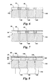
- each of the grooves 132 has a base 134, and, as shown for example in FIGS. 9 and 10 , extends at least partially along the substrate 110.
- the grooves 132 are shown in FIG. 4 as being formed entirely in the structural coating 54, for certain arrangements the grooves 132 may extend through the structural coating 54 and into the substrate 110. For certain arrangements the grooves 132 may extend only partially through the structural coating 54, such that some coating remains between the groove 132 and the substrate 110.
- the grooves are shown as having straight walls, the grooves 132 can have any configuration, for example, they may be straight, curved, or have multiple curves.
- the grooves 132 may be formed using a variety of techniques.
- the grooves 132 may be formed using one or more of an abrasive liquid jet, plunge electrochemical machining (ECM), electric discharge machining with a spinning single point electrode (milling EDM), and laser machining (laser drilling).
- ECM plunge electrochemical machining
- milling EDM electric discharge machining with a spinning single point electrode
- laser machining laser drilling.
- Example laser machining techniques are described in commonly assigned, US Patent Application Ser. No. 12/697,005 , "Process and system for forming shaped air holes” filed January 29, 2010, which is incorporated by reference herein in its entirety.
- Example EDM techniques are described in commonly assigned US Patent Application Ser. No. 12/790,675 , "Articles which include chevron film cooling holes, and related processes," filed May 28, 2010, which is incorporated by reference herein in its entirety.
- the grooves 132 are formed by directing an abrasive liquid jet 160 at the first layer of the structural coating 54, as schematically depicted in FIG. 4 .
- Example water jet drilling processes and systems are provided in commonly assigned US Patent Application Ser. No. 12/790,675 , "Articles which include chevron film cooling holes, and related processes," filed May 28, 2010, which is incorporated by reference herein in its entirety.
- the water jet process typically utilizes a high-velocity stream of abrasive particles (e.g., abrasive "grit"), suspended in a stream of high pressure water.
- the pressure of the water may vary considerably, but is often in the range of about 35-620 MPa.
- a number of abrasive materials can be used, such as garnet, aluminum oxide, silicon carbide, and glass beads.
- the water jet system can include a multi-axis computer numerically controlled (CNC) unit.
- CNC computer numerically controlled
- the CNC systems themselves are known in the art, and described, for example, in U.S. Patent Publication 200510013926 (S. Rutkowski et al ), which is incorporated herein by reference. CNC systems allow movement of the cutting tool along a number of X, Y, and Z axes, as well as rotational axes.
- the component fabrication method further includes depositing at least one additional coating 56, 57, 59 over the structural coating 54 and over the groove(s) 132, such that the groove(s) 132 and the additional coating(s) 56, 57, 59 together define one or more channels 130 for cooling the component 100.
- the grooves 132 and channels 130 are shown as being rectangular in FIGS. 4-9 , they may also take on other shapes.
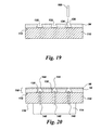
- the grooves 132 (and channels 130) may be re-entrant grooves 132 (re-entrant channels 130), as described below with reference to FIGS. 19 and 20 .
- the side-walls of the grooves 132 (channels 130) need not be straight.
- the side-walls of the grooves 132 (channels 130) may be curved or rounded.
- the component fabrication method further includes forming at least one exit hole 142 through the additional coating 56, 57, 59 for each of the respective channels 132, to receive and discharge coolant from the respective channel 130.
- the exit holes 142 may be formed, for example, using one or more of laser drilling, abrasive liquid jet, electric discharge machining (EDM) and electron beam drilling. It should be noted that EDM is typically limited in application, to forming holes through electrically conductive coatings.
- the cooling channel 130 conveys coolant from an access hole 140 to a film cooling hole 142. It should be noted that although the film holes are shown in FIG. 9 as being round, this is a non-limiting example. The film holes may also be non-circular shaped holes.
- the component fabrication method further includes forming one or more access holes 140 through the base 134 of a respective one of the grooves 132 to provide fluid communication between the grooves 132 and the hollow interior space(s) 114.
- the access holes 140 are formed prior to depositing the additional coating(s) 56, 57, 59.
- the access holes 140 are typically circular or oval in cross-section and may be formed, for example using on or more of laser machining (laser drilling), abrasive liquid jet, electric discharge machining (EDM) and electron beam drilling.
- the access holes 140 may be normal to the base 134 of the respective grooves 132 (as shown in FIG. 5 ) or, more generally, may be drilled at angles in a range of 20-90 degrees relative to the base 134 of the groove.
- the component fabrication method further includes filling the groove(s) 132 with a filler 32 ( FIG. 6 ) through the respective one or more openings 58 ( FIG. 5 ) in the structural coating 54.
- the filler may be applied by slurry, dip coating or spray coating the component 100 with a metallic slurry "ink" 32, such that the grooves 132 are filled.
- the filler 32 may be applied using a micro-pen or syringe.
- the grooves 132 may be over-filled with the filler material 32. Excess filler 32 may be removed, for example may be wiped off, for example using a doctor blade.
- Non-limiting example materials for the filler 32 include photo-curable resins (for example, visible or UV curable resins), ceramics, copper or molybdenum inks with an organic solvent carrier, and graphite powder with a water base and a carrier. More generally, the sacrificial filler 32 may comprise the particles of interest suspended in a carrier with an optional binder. Further, depending on the type of filler employed, the filler may or may not flow into the access holes 140.
- Example filler materials (or channel filling means or sacrificial materials) are discussed in commonly assigned, US Patent No. 5,640,767 and in commonly assigned, US Patent No.
- the additional coating 56 is deposited over the structural coating 54 and over the filler 32 disposed in the groove(s) 132.
- the filler 32 is removed from the groove(s) 132 after the additional coating 56, 59 has been deposited.
- access holes 140 are formed prior to filling the grooves 132 with the filler 32.
- the process shown in FIGS. 3-8 uses a filler 32 to keep the additional coating 56, 59 from filling the cooling channels 130, for other processes the grooves 132 are unfilled when the additional coating 56, 57, 59 is deposited.
- Examples of such processes include forming relatively narrow channels (for example, having widths in a range of about 0.2- 0.4 mm (8 to 15 mils) at the top opening where the coating bridges) and forming re-entrant shaped channels, as discussed below with reference to FIGS. 19 and 20 .
- the additional coating 56 shown in FIG. 7 comprises a second structural coating 56, such that the groove(s) 132 and the second structural coating 56 together defme the cooling channels 130.
- the structural coating comprises any suitable material and is bonded to the outer surface 112 of substrate 110.
- the first and/or second structural coating layers 54, 56 may have a thickness in the range of 0.02-2.0 millimeters, and more particularly, in the range of 0.1 to 1 millimeters, and still more particularly 0.1 to 0.5 millimeters for industrial gas turbine components. For aviation components, this range is typically 0.05 to 0.25 millimeters. However, other thicknesses may be utilized depending on the requirements for a particular component 100.
- the structural coatings 54, 56 comprise the same coating material. Using the same material for structural coatings 54, 56 has the advantage of providing strain relief in the coating, as well as the ability to shape the strain relief in the second coating.
- the two structural coatings 54, 56 may comprise different coating materials.
- the same deposition technique is used to deposit the structural coatings 54, 56.
- different deposition techniques are used to deposit the two structural coatings 54, 56. Example structural coating materials and deposition techniques are provided below.
- the component fabrication method further includes depositing an environmental coating 57, such as a bond coat or oxidation resistant coating over the second structural coating 56.
- Example environmental coatings include without limitation platinum aluminide, a MCrAlY overlay, or an overlay NiAl based coating.
- a thermal barrier coating 59 is deposited over the environmental coating 57.
- heat treatments may be employed depending on the coatings deposited.
- these methods may also include depositing additional coating layers 57, 59 over the second structural coating layer 56.
- a structural coating may be all that is used for the three concepts shown in FIGS. 3-8 , 11-18 and/or FIGS. 19-20 .
- the structural coating layers 54, 56 and optional additional coating layer(s) 57, 59 may be deposited using a variety of techniques.
- structural coating layers 54, 56 are deposited by performing an ion plasma deposition (cathodic arc).
- Example ion plasma deposition apparatus and method are provided in commonly assigned, US Published Patent Application No. 20080138529, Weaver et al , "Method and apparatus for cathodic arc ion plasma deposition," which is incorporated by reference herein in its entirety.
- ion plasma deposition comprises placing a cathode formed of a coating material into a vacuum environment within a vacuum chamber, providing a substrate 110 within the vacuum environment, supplying a current to the cathode to form a cathodic arc upon a cathode surface resulting in arc-induced erosion of coating material from the cathode surface, and depositing the coating material from the cathode upon the substrate surface 112.
- Non-limiting examples of a coating deposited using ion plasma deposition include structural coatings 54, 56, as well as bond coatings and oxidation-resistant coatings, as discussed in greater detail below with reference to US Patent No. 5,626,462 .
- the structural coating 54, 56 comprises a nickel-based or cobalt-based alloy, and more particularly comprises a superalloy or a (NiCo)CrAlY alloy.
- structural coating 54, 56 may comprise similar compositions of materials, as discussed in greater detail below with reference to US Patent No. 5,626,462 .
- structural coating layers 54, 56 are deposited by performing at least one of a thermal spray process and a cold spray process.
- the thermal spray process may comprise combustion spraying or plasma spraying
- the combustion spraying may comprise high velocity oxygen fuel spraying (HVOF) or high velocity air fuel spraying (HVAF)
- the plasma spraying may comprise atmospheric (such as air or inert gas) plasma spray, or low pressure plasma spray (LPPS, which is also know as vacuum plasma spray or VPS).
- LPPS low pressure plasma spray
- a NiCrAlY coating is deposited by HVOF or HVAF.
- Other example techniques for depositing structural coating layers 54, 56 include, without limitation, sputtering, electron beam physical vapor deposition, electroless plating, and electroplating.
- a first structural coating layer may be deposited using an ion plasma deposition, and a subsequently deposited layer and optional additional layers (not shown) may be deposited using other techniques, such as a combustion spray process or a plasma spray process.
- a combustion spray process or a plasma spray process.
- the use of different deposition techniques for the coating layers may provide benefits in properties, such as, but not restricted to strain tolerance, strength, adhesion, and/or ductility.
- the material used to form coating 150 comprises any suitable material.
- the structural coating material must be capable of withstanding temperatures up to about 1150° C, while the TBC can withstand temperatures up to about 1425° C.
- the structural coating 54, 56 must be compatible with and adapted to be bonded to the airfoil-shaped outer surface 112 of substrate 110, as discussed in commonly assigned, US. Patent Application. Ser. No. 12/943,563, Bunker et al. "Method of fabricating a component using a fugitive coating," which patent application is hereby incorporated herein in its entirety.
- the materials for the structural coating 54, 56 may comprise similar compositions of materials to the substrate.
- Such a combination of coating 54, 56 and substrate 110 materials is preferred for particular applications, such as where the maximum temperatures of the operating environment (that is, the gas temperatures) are similar to those of existing engines (e.g. below 1650° C.)
- the structural coating 54, 56 may likewise comprise similar material compositions.
- the structural coating 54, 56 comprise composites.
- the composites can consist of a mixture of intermetallic and metal alloy phases or a mixture of intermetallic phases.
- the metal alloy may be the same alloy as used for the substrate 110 or a different material, depending on the requirements of the component 100. Further, the two constituent phases must be chemically compatible, as discussed in US. Patent Application. Ser. No. 12/943,563, Bunker et al. It is also noted that within a given coating, multiple composites may also be used, and such composites are not limited to two-material or two-phase combinations. Additional details regarding example structural coating materials are provided in US Patent No. 5,626,462 .
- each of the grooves 132 has a base 134 and a top 136, where the base 134 is wider than the top 136, such that each of the grooves 132 comprises a re-entrant shaped groove 132.
- the base 134 of a respective one of the re-entrant shaped grooves 132 is at least two times wider than the top 136 of the respective groove 132.
- the base 134 of the respective re-entrant shaped groove 132 is at least three times, and more particularly, is in a range of about 3-4 times wider than the top 136 of the respective groove 132.
- re-entrant grooves 132 are provided in commonly assigned, US Patent Application, Ser. No. 12/943,624, Ronald S. Bunker et al. , "Components with re-entrant shaped cooling channels and methods of manufacture," which patent application is incorporated by reference herein in its entirety.
- the additional coating 56, 59 can be deposited over unfilled re-entrant grooves 132 (that is, without the filling or partial filling the groove with a sacrificial filler), as indicated for example in FIGS. 19 and 20 .
- the re-entrant grooves provide enhanced cooling relative to a simple shaped groove (namely, grooves with tops 136 and bases of approximately equal width).
- the grooves may be small enough, such that the additional coating 56, 59 can be deposited over unfilled grooves 132 (with arbitrary shapes, that is they need not be re-entrant shaped) without filling or partial filling of the groove. This could be the case for smaller, for example aviation-sized, components.
- the additional coating 56, 59 comprises a structural coating 56 and defines one or more permeable slots 144 (porous gaps 144), such that the structural coating 56 does not completely bridge each of the one or more grooves 132.
- the additional coating 56 completely bridges the respective grooves 132, thereby sealing the respective channels 130.
- the permeable slots 144 are shown for the case of re-entrant channels 130, permeable slots 144 may also be formed for other channel geometries.
- the permeable slots (gaps) 144 have irregular geometries, with the width of the gap 144 varying, as the structural coating is applied and builds up a thickness.
- the width of the gap 144 may narrow from approximately the width of the top 136 of the channel 130, as the structural coating is built up.
- the width of gap 144, at its narrowest point is 5% to 20% of the width of the respective channel top 136.
- the permeable slot 144 may be porous, in which case the "porous" gap 144 may have some connections, that is, some spots or localities that have zero gap.
- the gaps 144 provide stress relief for the coating 150.
- the permeable slots 144 may extend either (1) through all of the coating layers or (2) through some but not all coatings, for example, a permeable slot 144 may be formed in one or more coating layers with a subsequently deposited layer bridging the slots, thereby effectively sealing the slots 144.
- the permeable slot 144 functions as a stress/strain relief for the structural coating(s).
- the permeable slot 144 can serve as a cooling means when it extends through all coatings, that is for this configuration, the permeable slots 144 are configured to convey a coolant fluid from the respective channels 130 to an exterior surface of the component. Further, the permeable slot 144 can serve as a passive cooling means when bridged by the upper coatings, in the case when those coatings are damaged or spalled.
- the component fabrication method further includes performing a heat treatment after depositing the structural coating 54. Additional heat treatments may be performed after depositing a second structural coating layer 56 and/or after deposition of additional coating layers 59.
- the coated component 100 may be heated to a temperature in a range of about 0.7-0.9 Tm after the deposition of the second structural coating layer 56, where Tm is the melting temperature of the coating in degrees Kelvin.
- this heat treatment promotes the interdiffusion and subsequent adhesion of the two layers 54, 56 of the structural coating to one another, thereby reducing the likelihood of interfacial flaws at the channel edges.
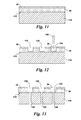
- the component fabrication method further includes depositing a fugitive coating 30 on the structural coating 54 prior to machining the structural coating 54, as indicated for example in FIGS. 11 and 12 .
- the structural coating 54 is machined through the fugitive coating 30, as indicated in FIG. 12 .
- the machining forms one or more openings 34 in the fugitive coating 30, as shown in FIG. 13 .
- the component fabrication method may optionally further include drying, curing or sintering the fugitive coating 30 prior to machining the structural coating 54.
- the thickness of the fugitive coating 30 deposited on the structural coating 54 is in a range of about 0.5-2.0 millimeters.
- the fugitive coating 30 comprises a one millimeter thick polymer based coating.
- the fugitive coating 30 may be deposited using a variety of deposition techniques, including powder coating, electrostatic coating, dip-coating, spin coating, chemical vapor deposition and application of a prepared tape. More particularly, the fugitive coating is essentially uniform and is able to adhere, but does not harm the structural coating 54 during processing or subsequent removal.
- the fugitive coating 30 is deposited using powder coating or electrostatic coating.
- the fugitive coating 30 comprises a polymer.
- the fugitive coating 30 may comprise a polymer based coating, such as pyridine, which may be deposited using chemical vapor deposition.
- Other example polymer based coating materials include resins, such as polyester or epoxies.
- Example resins include photo-curable resins, such as a light curable or UV curable resin, non-limiting examples of which include a UV/Visible light curable masking resin, marketed under the trademark Speedmask 729® by DYMAX, having a place of business in Torrington, Connecticut, in which case, the method further includes curing the photo-curable resin 30, prior to forming the grooves 132.
- the fugitive coating 30 may comprise a carbonaceous material.
- the fugitive coating 30 may comprise graphite paint.
- Polyethylene is yet another example coating material.
- the fugitive coating 30 may be enameled onto the structural coating 54.
- the fugitive coating 30 is removed prior to depositing the additional coating 56, 59.
- the fugitive coating 30 may be removed using mechanical (for example, polishing), thermal (for example combustion), plasma-based (for example plasma etching) or chemical (for example, dissolution in a solvent) means or using a combination thereof.
- the method further includes drying, curing or sintering the fugitive coating 30 prior to machining the structural coating 54.
- the fugitive coating 30 acts as a machining mask for formation of the channels, and facilitates the formation of cooling channels 130 with the requisite sharp, well defmed edges at the coating interface.
- the component fabrication method illustrated in FIGS. 11-18 further includes filling the groove(s) 132 with a filler 32 through the opening(s) 58 in the structural coating 54.
- the fugitive coating 30 may be removed prior to filling the grooves with the filler 32.
- the filler 32 is deposited in the grooves 132 through the respective opening(s) 58 in the first structural coating layer 54 and through the respective opening(s) 34 in the fugitive coating 30, prior to the removal of the fugitive coating 30.
- the component fabrication method further includes removing the fugitive coating 30 prior to depositing the additional coating 56.
- the additional coating 56 is deposited over the structural coating 54 and over the filler 32 disposed in the groove(s) 132.
- the component fabrication method may optionally include drying, curing or sintering the filler 32 prior to the deposition of the additional coating 56.
- the component fabrication method further includes removing the filler 32 from the groove(s) 132 after the additional coating 56 has been deposited.
- the component 100 includes a substrate 110 comprising an outer surface 112 and an inner surface 116.
- the inner surface 116 defines at least one hollow, interior space 114.
- the component 100 further includes a structural coating 54 disposed over at least a portion of the outer surface 112 of the substrate 110.
- the structural coating 54 defines one or more grooves 132.
- FIGS. 2 , 4 , 5 , 9 , 10 , 12 , 13 , and 19 the structural coating 54 defines one or more grooves 132.
- each of the grooves 132 extends at least partially along the substrate 110 and has a base 134.
- the grooves are shown as having straight walls, the grooves 132 can have any configuration, for example, they may be straight, curved, or have multiple curves. Further, the grooves may be formed entirely within the structural coating 54, as shown in FIG. 2 , or may extend into the substrate 110.
- One or more access holes 140 extend through the base 134 of a respective groove 132 to place the groove 132 in fluid communication with the interior space(s) 114, as shown for example in FIGS. 8 , 18 and 20 .
- the access holes 140 may be normal to the base 134 of the respective grooves 132 (as shown in FIG. 8 , 18 and 20 ) or may be drilled at angles in a range of 20-90 degrees relative to the base 134 of the groove 132.
- the component 100 further includes at least one additional coating 56, 59 disposed over the structural coating 54 and over the groove(s) 132, such that the groove(s) 132 and the additional coating 56, 59 together define one or more channels 130 for cooling the component 100.
- each cooling channel 130 has a width in the range of about 0.2-1.0 mm.
- a cooling channel 130 should be in the range of about 0.2-1.0 mm (8 to 40 mils) wide if the channels are to be coated using a sacrificial filler with subsequent removal thereof If the coating is applied to the cooling channels without the use of a sacrificial filler, the cooling channels 130 should be in the range of about 0.2-0.4 mm (8 to 15 mils) wide at the top opening where the coating bridges.
- At least one exit hole 142 extends through the additional coating 56, 59 for each of the respective channels 130, to receive and discharge a coolant fluid from the respective channel 130.
- the cooling channel 130 conveys coolant from an access hole 140 to a film cooling hole 142.
- the film holes are shown in FIG. 9 as being round, this is a non-limiting example.
- the film holes may also be non-circular shaped holes.
- the additional coating 56, 57, 59 comprises a second structural coating 56.
- the structural coatings 54, 56 comprise the same coating material. More generally, for these configurations, the structural coatings 54, 56 may have similar or essentially identical properties. For example, the two layers may be formed of the same material deposited using the same technique under similar or identical conditions.
- the structural coatings 54, 56 may comprise different coating materials. More generally, the structural coatings 54, 56 may differ in at least one property selected from the group consisting of density, roughness, porosity and coefficient of thermal expansion.
- the structural coating 54 may be denser and smoother than the structural coating 56 (that is, the structural coating 56 may be rougher or more porous than the structural coating 54). This can be achieved, for example, by depositing the two structural coatings 54, 56 using different deposition techniques.
- the first structural coating 54 has an average roughness R A as determined by cone stylus profilometry of about 1.5 to 2.5 microns
- the second structural coating 56 has an average roughness R A as determined by cone stylus profilometry of about 5 to 10 microns.
- the structural coating 54 has a thickness of less than about 1.0 mm, and more particularly, less than about 0.5 mm, and still more particularly has a thickness in a range of about 0.25-0.5 mm, and the second structural coating 56 has a thickness in a range of about 0.1-0.5 mm.
- the thickness may be less than about 0.5 mm, whereas for structural coatings 54 deposited by HVOF, the thickness may be less than about 1.0 mm. More particularly, the thickness of the first structural coating 54 is in a range of about 0.2-0.5 mm, and the thickness of the second structural coating 56 is in a range of about 0.125-0.25 mm.
- the component 100 may further include a thermal barrier coating 59 disposed over a second structural coating 56.
- the additional coatings 56, 57, 59 may include an environmental coating 57.
- Example environmental coatings include without limitation platinum aluminide, a MCrAlY overlay, or an overlay NiAl based coating.
- a thermal barrier coating 59 is deposited over the environmental coating 57.
- this re-entrant channel configuration may also include additional coating layers 57, 59 disposed over the second structural coating layer 56.
- a structural coating 56 may be all that is used.
- the second structural coating 56 defines one or more permeable slots 144, such that the second structural coating 56 does not completely bridge each of the one or more grooves 132.
- permeable slots 144 are shown in FIGS. 19 and 20 for the case of re-entrant channels 130, permeable slots 144 may also be formed for other channel geometries.
- the permeable slot 144 can serve as a cooling means when it extends through all additional coatings, that is for these configurations, the permeable slots 144 are configured to convey a coolant fluid from the respective channels 130 to an exterior surface of the component.
- the permeable slot(s) 144 may serve as a passive cooling means when bridged by a bond coat 57 and optionally a TBC 59, for example, in the case when those coatings are damaged or spalled.
- the formation of permeable slots 144 is described in commonly assigned, US Patent Application Ser. No. 12/943,646, Ronald Scott Bunker et al. , "Component and methods of fabricating and coating a component," which patent application is hereby incorporated by reference herein in its entirety.
- the additional coating 56 completely bridges the respective grooves 132, thereby sealing the respective channels 130.
- This particular configuration can be achieved, for example, by rotating the substrate 110 about one or more axes during deposition of the second coating layer 56 or by otherwise depositing the second coating layer 56 at an incidence angle inclined more than about +/- 20 degrees from the surface normal of the substrate 110, in order to substantially coat over the opening 58 formed in the first coating layer 54.
- Other techniques for producing a continuous additional coating 56 would be to apply an alternate (relative to layer 54) type of second coating, such as an air plasma spray coating, or to apply a thicker additional coating 56, as described in US Patent Application Ser. No. 12/943,646, Bunker et al.
- the base 134 is wider than the top 136 for each of the grooves 132, such that each of the grooves 132 comprises a re-entrant shaped groove 132 and hence, each of the cooling channels 130 comprises a re-entrant shaped channel 130.
- re-entrant shaped channel 130 as well as techniques for forming re-entrant shaped channel 130 are described in US Patent Application, Ser. No. 12/943,624, Bunker et al.
- the configuration shown in FIG. 20 may further include a thermal barrier coating 59 disposed over a second structural coating 56.
- cooling channels in the structural coating enhances thermal protection of the load bearing substrate, relative to conventional cooling channels formed under the structural coating.
- forming the cooling channels entirely within the structural coating eliminates structural and/or strength concerns associated with machining channels into the substrate.
Landscapes
- Engineering & Computer Science (AREA)
- Mechanical Engineering (AREA)
- General Engineering & Computer Science (AREA)
- Turbine Rotor Nozzle Sealing (AREA)
Applications Claiming Priority (1)
| Application Number | Priority Date | Filing Date | Title |
|---|---|---|---|
| US13/052,415 US20120243995A1 (en) | 2011-03-21 | 2011-03-21 | Components with cooling channels formed in coating and methods of manufacture |
Publications (1)
| Publication Number | Publication Date |
|---|---|
| EP2503099A2 true EP2503099A2 (fr) | 2012-09-26 |
Family
ID=45874683
Family Applications (1)
| Application Number | Title | Priority Date | Filing Date |
|---|---|---|---|
| EP12159559A Withdrawn EP2503099A2 (fr) | 2011-03-21 | 2012-03-15 | Composants avec canaux de refroidissement formés dans des revêtements et procédé de fabrication |
Country Status (3)
| Country | Link |
|---|---|
| US (1) | US20120243995A1 (fr) |
| EP (1) | EP2503099A2 (fr) |
| CN (1) | CN102691533A (fr) |
Cited By (3)
| Publication number | Priority date | Publication date | Assignee | Title |
|---|---|---|---|---|
| EP2728033A1 (fr) * | 2012-10-30 | 2014-05-07 | General Electric Company | Composants de couche de revêtement à motifs micro-refroidis et procédés de fabrication |
| EP2728034A1 (fr) * | 2012-10-30 | 2014-05-07 | General Electric Company | Composants de couche de revêtement micro-refroidi et procédés de fabrication |
| EP2728119A1 (fr) * | 2012-11-06 | 2014-05-07 | General Electric Company | Composant de turbine refroidie à microcanaux et procédé de formation d'un composant de turbine refroidie à microcanaux |
Families Citing this family (25)
| Publication number | Priority date | Publication date | Assignee | Title |
|---|---|---|---|---|
| US8673397B2 (en) | 2010-11-10 | 2014-03-18 | General Electric Company | Methods of fabricating and coating a component |
| US8387245B2 (en) * | 2010-11-10 | 2013-03-05 | General Electric Company | Components with re-entrant shaped cooling channels and methods of manufacture |
| US8601691B2 (en) | 2011-04-27 | 2013-12-10 | General Electric Company | Component and methods of fabricating a coated component using multiple types of fillers |
| US9206696B2 (en) | 2011-08-16 | 2015-12-08 | General Electric Company | Components with cooling channels and methods of manufacture |
| US20130086784A1 (en) | 2011-10-06 | 2013-04-11 | General Electric Company | Repair methods for cooled components |
| CH706090A1 (de) * | 2012-02-17 | 2013-08-30 | Alstom Technology Ltd | Verfahren zum Herstellen eines oberflächennahen Kühlkanals in einem thermisch hoch beanspruchten Bauteil sowie Bauteil mit einem solchen Kanal. |
| US9435208B2 (en) | 2012-04-17 | 2016-09-06 | General Electric Company | Components with microchannel cooling |
| US9303517B2 (en) * | 2012-06-15 | 2016-04-05 | General Electric Company | Channel marker and related methods |
| DE102013109116A1 (de) | 2012-08-27 | 2014-03-27 | General Electric Company (N.D.Ges.D. Staates New York) | Bauteil mit Kühlkanälen und Verfahren zur Herstellung |
| US9238265B2 (en) | 2012-09-27 | 2016-01-19 | General Electric Company | Backstrike protection during machining of cooling features |
| US20140116660A1 (en) * | 2012-10-31 | 2014-05-01 | General Electric Company | Components with asymmetric cooling channels and methods of manufacture |
| DE102013111874A1 (de) * | 2012-11-06 | 2014-05-08 | General Electric Company | Bauteil mit hinterschnitten geformten Kühlkanälen und Herstellungsverfahren dazu |
| US20140137408A1 (en) * | 2012-11-16 | 2014-05-22 | General Electric Company | Methods of fabricating and coating turbine components |
| US20140170433A1 (en) * | 2012-12-19 | 2014-06-19 | General Electric Company | Components with near-surface cooling microchannels and methods for providing the same |
| US9970311B2 (en) * | 2013-03-05 | 2018-05-15 | United Technologies Corporation | Consumable assembly tool for a gas turbine engine |
| US20160010466A1 (en) * | 2013-03-15 | 2016-01-14 | United Technologies Corporation | Gas turbine engine component with twisted internal channel |
| US9476306B2 (en) | 2013-11-26 | 2016-10-25 | General Electric Company | Components with multi-layered cooling features and methods of manufacture |
| US10859267B2 (en) * | 2013-12-18 | 2020-12-08 | Raytheon Technologies Corporation | Oxidation resistant thermal barrier coating system for combustor panels |
| US20160305004A1 (en) * | 2015-04-20 | 2016-10-20 | Honeywell International Inc. | Coated substrates and methods of producing the same |
| US10260363B2 (en) * | 2016-12-08 | 2019-04-16 | General Electric Company | Additive manufactured seal for insert compartmentalization |
| US10927680B2 (en) * | 2017-05-31 | 2021-02-23 | General Electric Company | Adaptive cover for cooling pathway by additive manufacture |
| US11313041B2 (en) | 2018-07-17 | 2022-04-26 | National Research Council Of Canada | Manufactured metal objects with hollow channels and method for fabrication thereof |
| US10982855B2 (en) | 2018-09-28 | 2021-04-20 | General Electric Company | Combustor cap assembly with cooling microchannels |
| US12331382B2 (en) * | 2019-05-06 | 2025-06-17 | Kennametal Inc. | Sintered alloy articles and methods of making the same |
| CN113027535B (zh) * | 2019-12-24 | 2022-10-11 | 中国航发商用航空发动机有限责任公司 | 涡轮叶片和航空发动机 |
Citations (6)
| Publication number | Priority date | Publication date | Assignee | Title |
|---|---|---|---|---|
| US5626426A (en) | 1995-04-26 | 1997-05-06 | Nsk Ltd. | Self-aligning roller bearing with retainer |
| US5626462A (en) | 1995-01-03 | 1997-05-06 | General Electric Company | Double-wall airfoil |
| US5640767A (en) | 1995-01-03 | 1997-06-24 | Gen Electric | Method for making a double-wall airfoil |
| US6321449B2 (en) | 1998-11-12 | 2001-11-27 | General Electric Company | Method of forming hollow channels within a component |
| US20050013926A1 (en) | 2003-07-17 | 2005-01-20 | General Electric Company | Robotic pen |
| US20080138529A1 (en) | 2006-12-11 | 2008-06-12 | Ge Global Research Center | Method and apparatus for cathodic arc ion plasma deposition |
Family Cites Families (26)
| Publication number | Priority date | Publication date | Assignee | Title |
|---|---|---|---|---|
| RU2168558C2 (ru) * | 1995-07-25 | 2001-06-10 | Сименс Акциенгезелльшафт | Изделие с металлическим основным телом и способ его изготовления |
| DE19737845C2 (de) * | 1997-08-29 | 1999-12-02 | Siemens Ag | Verfahren zum Herstellen einer Gasturbinenschaufel, sowie nach dem Verfahren hergestellte Gasturbinenschaufel |
| US6617003B1 (en) * | 2000-11-06 | 2003-09-09 | General Electric Company | Directly cooled thermal barrier coating system |
| US6444259B1 (en) * | 2001-01-30 | 2002-09-03 | Siemens Westinghouse Power Corporation | Thermal barrier coating applied with cold spray technique |
| US7141812B2 (en) * | 2002-06-05 | 2006-11-28 | Mikro Systems, Inc. | Devices, methods, and systems involving castings |
| US20030077434A1 (en) * | 2001-10-19 | 2003-04-24 | Franz Jansen | Method for manufacturing a thermally sprayed layer |
| US7186091B2 (en) * | 2004-11-09 | 2007-03-06 | General Electric Company | Methods and apparatus for cooling gas turbine engine components |
| WO2006069941A1 (fr) * | 2004-12-24 | 2006-07-06 | Alstom Technology Ltd | Composant comprenant un canal incorpore, en particulier composant a gaz chauds d'une turbomachine |
| DE102005060243A1 (de) * | 2005-12-14 | 2007-06-21 | Man Turbo Ag | Verfahren zum Beschichten einer Schaufel und Schaufel einer Gasturbine |
| US7553534B2 (en) * | 2006-08-29 | 2009-06-30 | General Electric Company | Film cooled slotted wall and method of making the same |
| US7625180B1 (en) * | 2006-11-16 | 2009-12-01 | Florida Turbine Technologies, Inc. | Turbine blade with near-wall multi-metering and diffusion cooling circuit |
| US20100078418A1 (en) * | 2008-09-26 | 2010-04-01 | Electro Scientific Industries, Inc. | Method of laser micro-machining stainless steel with high cosmetic quality |
| US8651805B2 (en) * | 2010-04-22 | 2014-02-18 | General Electric Company | Hot gas path component cooling system |
| US9249491B2 (en) * | 2010-11-10 | 2016-02-02 | General Electric Company | Components with re-entrant shaped cooling channels and methods of manufacture |
| US20120148769A1 (en) * | 2010-12-13 | 2012-06-14 | General Electric Company | Method of fabricating a component using a two-layer structural coating |
| US8753071B2 (en) * | 2010-12-22 | 2014-06-17 | General Electric Company | Cooling channel systems for high-temperature components covered by coatings, and related processes |
| US8533949B2 (en) * | 2011-02-14 | 2013-09-17 | General Electric Company | Methods of manufacture for components with cooling channels |
| US20120295061A1 (en) * | 2011-05-18 | 2012-11-22 | General Electric Company | Components with precision surface channels and hybrid machining method |
| US9327384B2 (en) * | 2011-06-24 | 2016-05-03 | General Electric Company | Components with cooling channels and methods of manufacture |
| US9216491B2 (en) * | 2011-06-24 | 2015-12-22 | General Electric Company | Components with cooling channels and methods of manufacture |
| US9206696B2 (en) * | 2011-08-16 | 2015-12-08 | General Electric Company | Components with cooling channels and methods of manufacture |
| US20130078418A1 (en) * | 2011-09-23 | 2013-03-28 | General Electric Company | Components with cooling channels and methods of manufacture |
| US20130101761A1 (en) * | 2011-10-21 | 2013-04-25 | General Electric Company | Components with laser cladding and methods of manufacture |
| US9200521B2 (en) * | 2012-10-30 | 2015-12-01 | General Electric Company | Components with micro cooled coating layer and methods of manufacture |
| US20140116660A1 (en) * | 2012-10-31 | 2014-05-01 | General Electric Company | Components with asymmetric cooling channels and methods of manufacture |
| US20140302278A1 (en) * | 2013-04-09 | 2014-10-09 | General Electric Company | Components with double sided cooling features and methods of manufacture |
-
2011
- 2011-03-21 US US13/052,415 patent/US20120243995A1/en not_active Abandoned
-
2012
- 2012-03-15 EP EP12159559A patent/EP2503099A2/fr not_active Withdrawn
- 2012-03-21 CN CN2012100906623A patent/CN102691533A/zh active Pending
Patent Citations (6)
| Publication number | Priority date | Publication date | Assignee | Title |
|---|---|---|---|---|
| US5626462A (en) | 1995-01-03 | 1997-05-06 | General Electric Company | Double-wall airfoil |
| US5640767A (en) | 1995-01-03 | 1997-06-24 | Gen Electric | Method for making a double-wall airfoil |
| US5626426A (en) | 1995-04-26 | 1997-05-06 | Nsk Ltd. | Self-aligning roller bearing with retainer |
| US6321449B2 (en) | 1998-11-12 | 2001-11-27 | General Electric Company | Method of forming hollow channels within a component |
| US20050013926A1 (en) | 2003-07-17 | 2005-01-20 | General Electric Company | Robotic pen |
| US20080138529A1 (en) | 2006-12-11 | 2008-06-12 | Ge Global Research Center | Method and apparatus for cathodic arc ion plasma deposition |
Cited By (7)
| Publication number | Priority date | Publication date | Assignee | Title |
|---|---|---|---|---|
| EP2728033A1 (fr) * | 2012-10-30 | 2014-05-07 | General Electric Company | Composants de couche de revêtement à motifs micro-refroidis et procédés de fabrication |
| EP2728034A1 (fr) * | 2012-10-30 | 2014-05-07 | General Electric Company | Composants de couche de revêtement micro-refroidi et procédés de fabrication |
| JP2014087924A (ja) * | 2012-10-30 | 2014-05-15 | General Electric Co <Ge> | マイクロ冷却される皮膜層を備えた構成要素及び製造方法 |
| US9200521B2 (en) | 2012-10-30 | 2015-12-01 | General Electric Company | Components with micro cooled coating layer and methods of manufacture |
| US9562436B2 (en) | 2012-10-30 | 2017-02-07 | General Electric Company | Components with micro cooled patterned coating layer and methods of manufacture |
| EP2728119A1 (fr) * | 2012-11-06 | 2014-05-07 | General Electric Company | Composant de turbine refroidie à microcanaux et procédé de formation d'un composant de turbine refroidie à microcanaux |
| EP2728119B1 (fr) | 2012-11-06 | 2016-02-03 | General Electric Company | Composant de turbine refroidie à microcanaux et procédé de formation d'un composant de turbine refroidie à microcanaux |
Also Published As
| Publication number | Publication date |
|---|---|
| US20120243995A1 (en) | 2012-09-27 |
| CN102691533A (zh) | 2012-09-26 |
Similar Documents
| Publication | Publication Date | Title |
|---|---|---|
| EP2503099A2 (fr) | Composants avec canaux de refroidissement formés dans des revêtements et procédé de fabrication | |
| EP2487330B1 (fr) | Composants avec canaux de refroidissement et procédés de fabrication | |
| US20120148769A1 (en) | Method of fabricating a component using a two-layer structural coating | |
| EP2518270B1 (fr) | Composant et procédés de fabrication d'un composant revêtu à l'aide de plusieurs types d'agents de remplissage | |
| US8727727B2 (en) | Components with cooling channels and methods of manufacture | |
| EP2511475B1 (fr) | Procédé de fabrication d'un composant pour un moteur à turbine à gaz | |
| US8673397B2 (en) | Methods of fabricating and coating a component | |
| EP2653655B1 (fr) | Composants avec refroidissement par microcanaux | |
| US9216491B2 (en) | Components with cooling channels and methods of manufacture | |
| EP2604796B1 (fr) | Composants des turbines à gaz avec microcanaux de refroidissement | |
| US20120114868A1 (en) | Method of fabricating a component using a fugitive coating | |
| EP2584150A2 (fr) | Composants avec placage laser et méthodes de fabrication | |
| EP2525044A2 (fr) | Composants avec canaux de surface de précision et procédé d'usinage hybride | |
| EP2537636B1 (fr) | Composant avec canaux de refroidissement et procédé de fabrication | |
| EP2728118A2 (fr) | Composants avec canaux de refroidissement asymétriques et procédés de fabrication |
Legal Events
| Date | Code | Title | Description |
|---|---|---|---|
| PUAI | Public reference made under article 153(3) epc to a published international application that has entered the european phase |
Free format text: ORIGINAL CODE: 0009012 |
|
| AK | Designated contracting states |
Kind code of ref document: A2 Designated state(s): AL AT BE BG CH CY CZ DE DK EE ES FI FR GB GR HR HU IE IS IT LI LT LU LV MC MK MT NL NO PL PT RO RS SE SI SK SM TR |
|
| AX | Request for extension of the european patent |
Extension state: BA ME |
|
| STAA | Information on the status of an ep patent application or granted ep patent |
Free format text: STATUS: THE APPLICATION IS DEEMED TO BE WITHDRAWN |
|
| 18D | Application deemed to be withdrawn |
Effective date: 20161001 |