EP2503206B1 - Raccord de flexibles - Google Patents
Raccord de flexibles Download PDFInfo
- Publication number
- EP2503206B1 EP2503206B1 EP12000300.9A EP12000300A EP2503206B1 EP 2503206 B1 EP2503206 B1 EP 2503206B1 EP 12000300 A EP12000300 A EP 12000300A EP 2503206 B1 EP2503206 B1 EP 2503206B1
- Authority
- EP
- European Patent Office
- Prior art keywords
- hose
- tear
- nipple
- protection ring
- coupling according
- Prior art date
- Legal status (The legal status is an assumption and is not a legal conclusion. Google has not performed a legal analysis and makes no representation as to the accuracy of the status listed.)
- Active
Links
Images



Classifications
-
- F—MECHANICAL ENGINEERING; LIGHTING; HEATING; WEAPONS; BLASTING
- F16—ENGINEERING ELEMENTS AND UNITS; GENERAL MEASURES FOR PRODUCING AND MAINTAINING EFFECTIVE FUNCTIONING OF MACHINES OR INSTALLATIONS; THERMAL INSULATION IN GENERAL
- F16L—PIPES; JOINTS OR FITTINGS FOR PIPES; SUPPORTS FOR PIPES, CABLES OR PROTECTIVE TUBING; MEANS FOR THERMAL INSULATION IN GENERAL
- F16L33/00—Arrangements for connecting hoses to rigid members; Rigid hose-connectors, i.e. single members engaging both hoses
- F16L33/20—Undivided rings, sleeves, or like members contracted on the hose or expanded inside the hose by means of tools; Arrangements using such members
- F16L33/207—Undivided rings, sleeves, or like members contracted on the hose or expanded inside the hose by means of tools; Arrangements using such members only a sleeve being contracted on the hose
- F16L33/2071—Undivided rings, sleeves, or like members contracted on the hose or expanded inside the hose by means of tools; Arrangements using such members only a sleeve being contracted on the hose the sleeve being a separate connecting member
- F16L33/2073—Undivided rings, sleeves, or like members contracted on the hose or expanded inside the hose by means of tools; Arrangements using such members only a sleeve being contracted on the hose the sleeve being a separate connecting member directly connected to the rigid member
- F16L33/2076—Undivided rings, sleeves, or like members contracted on the hose or expanded inside the hose by means of tools; Arrangements using such members only a sleeve being contracted on the hose the sleeve being a separate connecting member directly connected to the rigid member by plastic deformation
Definitions
- the invention relates to a hose coupling, in particular for high-pressure hoses, with a hose nipple intended to receive the hose, which on its outer circumference has a plurality of radially extending depressions and / or elevations lying one behind the other in the axial direction, with a cylinder-like press fitting that extends over the hose nipple and fixes the hose, which has radially extending ribs on its inner jacket and is provided at one end with an inwardly directed radial web which engages in a groove-like receptacle of the hose nipple when the press socket is pressed.
- Such hose couplings are used, for example, in hydraulic lines in which it is important to withstand high pressures of the medium being transferred without breaking the hose or the hose coupling.
- a high-pressure hose is usually multilayered and contains, in a known manner, a metal insert which is necessary for high-pressure applications.
- Such a hose coupling is for example in the document DE 201 06 932 U1 shown. Depending on the nominal width, however, these hose couplings cannot be used for heavy hydraulics because the press fittings are not designed for the tensile loads that occur there.
- a hose coupling according to FIG. 1 shows an improvement here EP 2 196 716 B1 .
- the hose coupling disclosed in this document can reliably absorb very high pressures and, in particular, also pulse-like pressure peaks due to the anti-tear device provided.
- a radially protruding wall deformation is provided on the inside of the press socket, which, in the case of attachment, can be affected by the The plastic layers of the hose press the metal insert that has been freed from the hose nipple.
- Such a non-positive and positive connection between the metallic press fitting, the metallic hose nipple and the metallic insert of the hose leads to a secure and tensile connection of the hose to the corresponding fitting.
- the object of the present invention is to improve the previous situation and to provide standard hose couplings or hose couplings with a pull-out protection with fewer parts to be stored for different nominal widths.
- a hose coupling with the features of claim 1, namely with a hose coupling consisting of a high-pressure hose, a tubular coupling element with a standard hose nipple, a press-fit fitting that can be deformed under radial pressure and a further component which is a retrofittable tear-out device.
- a standard hose coupling can be used both in the normal high pressure range and together with the installed anti-tear device for highest pressures and impulse-like pressure peaks.
- the invention reduces the components to be produced and stored for hose couplings of different nominal sizes and applications, since a coupling element with a standard hose nipple can be used both for standard applications and with the retrofittable tear-off protection for the highest pressures. So only one coupling element has to be provided for a nominal width.
- the new retrofittable anti-tear device is a metal anti-tear ring which can be retrofitted, for example, which can be pushed onto the hose nipple and fixed on the hose nipple, and which consists of a cylindrical section.
- This cylindrical section can consist of a closed ring, an open ring, several ring shell pieces or a spiral spring.
- an annular circumferential groove is formed, which serves to accommodate material of the metal insert of the hose during radial pressing and is located on the hose coupling opposite a first rib of the press socket in order to establish a positive connection between the press socket, the metal insert of the To enable hose and the pull-out protection.
- this anti-tear ring is positioned on the hose nipple and fixed in its position.
- holding means in particular holding means acting positively and / or non-positively, are provided on the tear-off locking ring.
- holding means are provided on the tear-off protection ring for such positioning, which means are preferably formed in one piece, ie integrally, with the cylindrical section of the tear-off protection ring.
- these holding means are provided on the inside of the tear-off locking ring in order to be able to interact with corresponding means of the hose nipple for positioning.
- a hose nipple is provided at the rear end of the tubular coupling element. At the front end, the coupling element can be connected to a fitting.
- the hose nipple points to Receiving the high-pressure hose on its outer circumference has a plurality of radially extending depressions lying one behind the other in the axial direction and rib-like elevations directed towards the high-pressure hose between the depressions.
- a recess and / or elevation present on the hose nipple is used for positioning the tear-off locking ring, preferably the first recess on the hose nipple starting from the front end of the coupling element.
- the aforementioned holding means of the tear-off locking ring can comprise one or more radially inwardly directed projections or grooves. In the simplest way, a radially inwardly directed circumferential rib is provided as a holding means on the anti-tear ring.
- the rib provided as a holding means can engage circumferentially in the first recess of the hose nipple during radial pressing.
- the positioning and fixing of this anti-tear ring can be carried out on the one hand together with the radial pressing of the press socket.
- this pull-out locking ring can, on the other hand, also be fixed in advance by radial pressing on the hose nipple.
- non-positively acting holding means are provided on the tear-off locking ring for positioning. For example, if a magnetized anti-tear ring is pushed onto the hose nipple until it hits the shoulder of the coupling element, it remains fixed against the metallic shoulder due to the magnetic attraction.
- retaining means in the form of one or more radially inwardly directed projections or grooves can also be provided for positioning and fixing the anti-tear ring on the hose nipple of the coupling element.
- a slotted ring does not have to be pressed onto the coupling element for assembly.
- the ring is made of an elastic material, the ring can be expanded to slide onto the hose nipple. Once the desired position has been reached, the ring can move back into its original shape and jam in one or more provided depressions and / or elevations on the hose nipple. The same applies to a spiral spring.
- the slotted ring is provided without additional holding means and is mounted on the hose nipple of the coupling element in the same way as described above.
- a slotted ring is preferably fixed via a form-fitting and / or force-fitting connection.
- the cylindrical section of the anti-tear ring consists of a plurality of annular shell pieces, preferably two half-shell pieces.
- a material connection This can be an adhesive connection or a welded or soldered connection.
- a closed ring consists of a metal material, preferably a steel alloy, and can be produced from a pipe section by non-cutting or cutting forming processes, for example by turning, deep drawing or hydroforming.
- a slotted ring consists of an elastic material, for example metal, preferably tempered steel, such as spring steel. It is produced as a ring from a pipe section by non-cutting or cutting forming processes, for example by turning, deep drawing or hydroforming, then tempered so that it retains its elastic properties and subsequently slotted, for example by erosion. The erosion enables an exact slot width to be provided in the ring.
- a ring can also consist of another elastic material, such as high-strength plastic, preferably of polyetheretherketone (PEEK).
- Ring shell pieces can consist of metal or high-strength plastic.
- the anti-tear ring has a circumferential groove on the outside of its cylindrical section. In a further embodiment of the anti-tear device, more than one circumferential groove is provided on the anti-tear device.
- the fastening position of the new hose coupling with a pull-out locking ring is achieved in the same way as with known hose couplings.
- the high-pressure hose in which a metal insert made of a wire mesh or at least one wire spiral winding is arranged between two plastic jackets, is freed from its inner and outer plastic jacket at one end and this end of the hose is inserted into the press socket and open together with the press socket the hose nipple with the pre-assembled anti-tear ring is pushed on. Finally, the press socket is pressed radially by external radial pressure.
- retaining means are present.
- this anti-tear ring is fixed on the hose nipple and the anti-tear ring is thus positioned on the hose nipple in its intended position.
- these are already fixed to the hose nipple before pressing.
- the metal insert of the hose is pressed by a rib of the press fitting into the circumferential groove of the anti-tear device and a non-positive and positive connection then occurs between the metallic press fitting, the metal insert of the hose, which may be metallic pull-out protection and the metallic hose nipple.
- the metallic components of the connection can weld together using the pressing force. This leads to a secure and tensile connection of the hose to the hose coupling.
- the connection area for the high-pressure hose in the hose coupling comprises two areas, namely the above-described front securing area with the tear-off protection and a sealing area adjoining it in the axial direction.
- the outer plastic jacket is preferably peeled off from the high-pressure hose, so that the ribs of the press socket engage in the metal insert during radial pressing and the elevation on the hose nipple can be pressed into the inner jacket of the hose.
- the radially inwardly directed ribs provided on the inner jacket of the press socket can be designed differently; the rib or ribs in the securing area are preferably larger than the ribs in the sealing area.
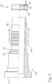
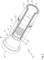
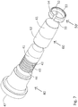
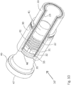
- FIGS. 1 to 5 an embodiment of the hose coupling 10 according to the invention is shown. It consists of a coupling element 40, a press socket 30 and a tear-off locking ring 50.
- a high-pressure hose 20 is connected to this hose coupling 10.
- This high-pressure hose 20 is provided with an inner and an outer plastic jacket 21, 23 which cover a metal insert 22.
- Such a high-pressure hose 20 can be used for very high pressures and high pulse loads.
- the end of the high-pressure hose 20 is peeled inside and outside, i.e. it has no outer plastic jacket 21 and no inner plastic jacket 23 in this front area of the hose coupling 10, which is referred to as securing area A, but consists exclusively of the metal insert 22.
- the high-pressure hose 20 has been freed from its outer plastic jacket 21.
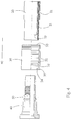
- the high-pressure hose 20 prepared in this way is, together with a press fitting 30 encompassing the high-pressure hose 20, onto the hose nipple 41 of the coupling element 40, as in FIG Fig. 4 indicated by the arrow, postponed.
- the coupling element 40 is a known coupling element 40 for standard applications, see FIG Fig. 2 .
- the coupling element 40 can be fixed to a desired fitting, for example with a union nut (not shown).
- the coupling element 40 has a hose nipple 41.
- This has a structure in the form of ribs 42 and depressions 43 on its outer surface.
- the ribs 42 press into its inner jacket 23 when the high-pressure hose 20 is pushed on.
- the first depressions 44 of the depressions 43 provided on the outer surface, as seen from the front end 47, are used in this exemplary embodiment for positioning the tear-off protection ring 50. It is also possible that several depressions are used to fix the tear-off protection ring 50.
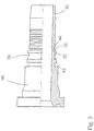
- the tear-off locking ring 50 shown has holding means 53 for its positioning on the hose nipple 41 on its inside 52.
- these holding means 53 consist of a radially inwardly directed circumferential rib, which as from Fig. 3 can be seen, when the pull-out locking ring 50 is pushed onto the hose nipple 41, it can be pressed into the first recess 44. This is possible because the anti-tear ring 50 is positioned when it is pushed onto the hose nipple 41 by resting against the shoulder 45 of the coupling element 40 in such a way that the holding means 53 are arranged opposite the first recess 44.
- the inside diameter of the anti-tear-off ring 50 is determined by the inside diameter of the rib serving as the holding means 53. This inner diameter is adapted to the outer diameter of the hose nipple 41 in such a way that the tear-off locking ring 50 can easily be pushed onto the hose nipple 41 until its front end rests on the shoulder 45, as in FIG Fig. 3 shown.
- the tear-off locking ring 50 shown also has a circumferential groove 55 on its outside 54. For larger hose couplings, tear-off safeguards with more than one circumferential groove can also be provided. Is the anti-tear ring 50, as in Fig.
- the coupling element 40 When pushed on, the coupling element 40 is comparable to a coupling element 40 with an integrally formed, ie molded-in, bulge for a pull-out protection.
- a circumferential groove 55 is provided adjacent to the shoulder 45, this circumferential groove 55 being delimited by two shoulders which protrude radially from the coupling element 40 and are dimensioned so large that they protrude significantly beyond the ribs 42 of the hose nipple 41.
- the pull-out protection ring 50 can be fixed on the hose nipple 41 by exerting slight radial pressure on the pull-out protection ring 50.
- a pre-fixing is not necessary to produce the fastening position of the hose coupling.
- the prepared high-pressure hose 20 is inserted into the press socket 30 and, together with the press socket 30, pushed onto the hose nipple 41, which is already provided with the anti-tear ring 50.
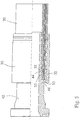
- This mounting position is in Fig. 5 shown.
- the high-pressure hose 20, together with the press socket 30, is pushed onto the coupling element 40 until an inwardly directed collar 35 is positioned at the front end 34 of the press socket 30 at the level of a circumferential groove 46 of the coupling element 40.
- the high-pressure hose 20 can be pushed up to this collar 35 of the press socket 30 and the peeled-free high-pressure hose 20, namely the metal insert 22, rests on the radially protruding shoulders of the tear-off locking ring 50, which delimit the circumferential groove 55.
- a first rib 32 of the press socket 30 is arranged opposite the circumferential groove 55.
- the press socket 30 can be seen better in its original form. Starting from the front end 34, where the inwardly directed collar 35 is provided, it has a structuring on the inside in the form of axially spaced radial ribs 31, 32.
- the first rib 32 is larger dimensioned rib, which is in the fastening position of the hose coupling 10 - see Fig. 1 - is located in security area A.
- the further ribs 31 are in the fastening position in the sealing area B.
- the ribs 31, 32 are preferably designed like teeth so that they can easily be pressed into the high-pressure hose 20 during radial pressing. It is of course also possible to provide the ribs 31, 32 in a spiral shape.
- the tear-off locking ring 50 is fixed at the same time on the hose nipple 41 by the holding means 53 engaging the first recess 44 on the hose nipple 41.
- FIGS. 6 to 10 a further embodiment of the hose coupling 10 'according to the invention is shown.
- the same reference numerals have been used for the same components.
- the same coupling element 40, the same press socket 30 and the same high-pressure hose 20 were used.
- a slotted ring is used as a tear-off locking ring 50 '.
- the first depressions 44 as seen from the front end 47, of the depressions 43 of the hose nipple 41 of the coupling element 40, which are provided on the outer surface, are used to position the tear-off locking ring 50 ′. It is also possible that several depressions are used to fix a slotted anti-tear ring Fig. 7
- the tear-off protection ring 50 'shown has holding means 53 on its inside 52 for its positioning on the hose nipple 41. In this case, these holding means 53 consist of a radially inwardly directed circumferential rib which, when the tear-off protection ring 50' is pushed onto the hose nipple 41, into the first recess 44 can be pressed in.
- a mounting sleeve 60 is used to push the anti-tear ring 50 'onto the hose nipple 41, which is shown in FIG Fig. 7 is shown.
- This mounting sleeve 60 has two areas 61, 62.
- the conical area 61 has its smallest diameter at the end of the mounting sleeve 60.
- the smallest diameter on the inside diameter of the relaxed anti-pull-out ring 50', as shown in FIG Fig. 7 shown is adjusted.
- the tear-off protection ring 50 ′ has a slot 57 and can therefore easily be pushed onto the area 61 of the mounting sleeve 60.
- the anti-tear ring 50' is expanded and reaches the second area 62 of the mounting sleeve 60.
- the second area 62 of the assembly sleeve is used to hold the anti-tear ring 50 'during assembly.
- the mounting sleeve 60 is pushed onto the hose nipple 41 together with the anti-tear ring 50 ′.
- the inner diameter of the mounting sleeve 60 is adapted to the outer diameter of the hose nipple 41.
- the mounting sleeve 60 can also have a stop on its inside, which prevents the mounting sleeve 60 from being pushed up to the shoulder 45 of the coupling element 40. In Fig. 8 the end position of such a mounting sleeve 60 is shown.
- the mounting sleeve 60 covers all the recesses 43 of the hose nipple 41 except for the first recess 44.
- the anti-tear ring 50 'held on the mounting sleeve 60 is then pushed forward, i.e.
- the anti-tear ring 50 ' is relaxed again, visible at the narrow slot 57.
- the inner diameter of the anti-tear ring 50' is adapted to the outer diameter of the hose nipple 41, in particular the inner diameter of the anti-tear ring 50 'in the area of the holding means 53 is adapted to the outer diameter of the Hose nipple 41 adapted in the region of the recess 44.
- the tear-off locking ring 50 ′ shown also has a circumferential groove 55 on its outside 54.
- tear-off safeguards with more than one circumferential groove can also be provided. Is the anti-tear ring 50 ', as in Fig. 9 shown, pushed onto the hose nipple 41, the prepared high-pressure hose 20 and the press socket 30 can be pushed onto the hose nipple 41 individually or together in a known manner. This situation is in Fig. 10 shown. A first rib 32 of the press socket 30 is arranged opposite the circumferential groove 55. To achieve the fastening position of the hose coupling 10 ', shown in FIG Fig.
- a pressure is exerted evenly radially on the press socket 30 in a special press, the ribs 31 engage in the Metal insert 22 of high pressure hose 20 and press high pressure hose 20 against hose nipple 41, which presses with its ribs 42 into inner jacket 23 of high pressure hose 20.
- the first rib 32 of the press socket 30 is simultaneously pressed into the circumferential groove 55 of the anti-tear ring 50 ', which results in a secure connection between the press socket 30, high-pressure hose 20 and hose nipple 41, namely a permanent metallic connection between hose nipple 41 with the metallic, the metal insert 22 and the rib 32 of the press socket 30.
- the collar 35 of the press socket 30 is simultaneously pressed into the circumferential groove 46 on the coupling element 40, which secures the press socket 30 on the coupling element 40.
- the mounting position is in Fig. 6 to see.
- the tear-off locking ring 50 ' was closed, the slot 57 has disappeared.
- the slot 57 must be adapted accordingly.
- a width of the slot 57 of 2.4 mm was selected for the relaxed tear-off locking ring 50 '.
- the slot 57 is preferably sized too large rather than too small.
- the slot 57 is axially aligned in the present exemplary embodiment, but other slot shapes and arrangements are also possible.
- the illustrated embodiments show that a hose coupling 10, 10 'can be used for the highest pressure applications and for pulse-like pressure peaks with a standard coupling without pull-out protection through the use of a retrofittable pull-out protection ring 50, 50' according to the invention.
- the tear-off locking ring 50, 50 ′ can be designed differently in accordance with the coupling element 40 used and the shape of the hose nipple 41.
- 10 ' different press sockets 30 are used, namely also press sockets, as they are in the European patent document EP 2 196 716 B1 are shown, in which the ribs 31, 32 are designed by wall deformations of the press socket, so that recesses are arranged opposite the radially inwardly directed projections on the outside.
Landscapes
- Engineering & Computer Science (AREA)
- General Engineering & Computer Science (AREA)
- Mechanical Engineering (AREA)
- Quick-Acting Or Multi-Walled Pipe Joints (AREA)
- Joints That Cut Off Fluids, And Hose Joints (AREA)
Claims (15)
- Raccord (10) de flexible, notamment pour conduites hydrauliques haute pression et conduites hydrauliques très haute pression,- comprenant un flexible haute pression (20) dans lequel est disposée, entre deux gaines (21, 23) en matière plastique, une garniture métallique (22) composée de fils tressés ou au moins d'un fil enroulé en spirale,- comprenant un élément de raccord (40) de type tubulaire raccordable par l'extrémité avant (47) à une robinetterie et qui présente à l'autre extrémité un nipple (41) de flexible servant à recevoir le flexible haute pression (20), lequel nipple (41) de flexible possède sur sa circonférence extérieure plusieurs creux (43) au tracé radialement juxtaposé dans le sens axial et, entre les creux (43), des nervures (42) dirigées vers le flexible haute pression (20),- sachant que la zone de raccordement du flexible haute pression (20) dans le raccord (10) de flexible comprend deux zones, à savoir une zone de sécurisation avant (A) comprenant une sécurisation anti-arrachement et une zone d'étanchéité (B) la jouxtant dans le sens axial,- comprenant une monture sertie (30) déformable sous une pression radiale, sachant que la monture sertie (30) présente, contre sa gaine intérieure, des nervures (31, 32) orientée en direction du flexible haute pression (20), sachant qu'au moins une nervure (32) de grande dimension est prévue dans la zone de sécurisation (A),- sachant que dans la zone de sécurisation (A) la garniture métallique (22) débarrassée des gaines (21, 23) en matière plastique est sertie entre le nipple (41) de flexible et la monture sertie (30),caractérisé en ce- que pour la sécurisation anti-arrachement est prévue dans la zone de sécurisation (A) une bague (50, 50') de sécurisation anti-arrachement enfilable sur le nipple (41) de flexible et immobilisable contre le nipple (41) de flexible, bague qui avant le sertissage se compose d'un segment cylindrique et qui possède sur son côté extérieur (54) au moins une gorge circonférentielle (55),- sachant que dans la position de montage du raccord (10) de flexible, la gorge circonférentielle (55) est dirigée radialement vers l'extérieur et en face de la nervure (32) de plus grande dimension contre la monture sertie (30) et que lors du sertissage radial elle sert à recevoir le matériau de la garniture métallique (22) du flexible haute pression (20),- de sorte qu'en position de fixation il y a présence d'une liaison par adhérence de forces et de formes entre la nervure (32) de la monture sertie (30), la garniture métallique (22) du flexible haute pression (20) et la bague de sécurisation anti-arrachement (50, 50') dans la zone de la gorge circonférentielle (55) et le nipple (41) de flexible.
- Raccord de flexible selon la revendication 1, caractérisé en ce que la bague de sécurisation anti-arrachement (50, 50') est en métal et qu'il y a présence d'une liaison métallique condamnée entre la nervure (32) de la monture sertie (30), la garniture métallique (22) du flexible haute pression (20), la bague de sécurisation anti-arrachement (50, 50') et le nipple (41) de flexible.
- Raccord de flexible selon la revendication 1 ou 2, caractérisé en ce que la bague de sécurisation anti-arrachement (50, 50') se compose d'un segment cylindrique (51) muni d'un moyen de retenue (53) pour le positionnement et/ou l'immobilisation contre le nipple (41) de flexible, sachant que les moyens de retenue (53) sont de préférence entièrement formés par le segment cylindrique (51).
- Raccord de flexible selon la revendication 3, caractérisé en ce que les moyens de retenue (53) sont prévus contre le côté intérieur (52) de la bague de sécurisation anti-arrachement (50) pour pouvoir engrener, dans un but d'immobilisation contre le nipple (41) de flexible, dans un creux (43) du nipple (41) de flexible.
- Raccord de flexible selon la revendication 4, caractérisé en ce que les moyens de retenue (53) comprennent une ou plusieurs saillies dirigées radialement vers l'intérieur, de préférence une nervure circonférentielle dirigée radialement vers l'intérieur.
- Raccord de flexible selon la revendication 3, caractérisé en ce qu'une magnétisation de la bague de sécurisation anti-arrachement (50) est prévue comme moyen de retenue.
- Raccord de flexible selon l'une des revendications 1 à 6, caractérisé en ce que la bague de sécurisation anti-arrachement (50, 50') applique, à l'état monté, contre un épaulement (45) de l'élément raccord (40).
- Raccord de flexible selon l'une des revendications 1 à 7, caractérisé en ce que la bague de sécurisation anti-arrachement (50) se compose d'un segment (51) cylindrique fermé du côté circonférentiel et qu'elle est présente prémontée par sertissage radial contre le nipple (41) de flexible.
- Raccord de flexible selon l'une des revendications 1 à 7, caractérisé en ce que la bague de sécurisation anti-arrachement (50') se compose d'un segment cylindrique élastique, de préférence d'un segment cylindrique avec fente (57, 57').
- Raccord de flexible selon l'une des revendications 1 à 7, caractérisé en ce que la bague de sécurisation anti-arrachement se compose d'un segment cylindrique composé de plusieurs parties d'une coque de bague, de préférence de deux demi-coques.
- Raccord de flexible selon la revendication 1, caractérisé en ce que la bague de sécurisation anti-arrachement (50, 50') est fabriquée en matière plastique haute résistance.
- Raccord de flexible selon l'une des revendications 1 à 11, caractérisé en ce que dans la zone d'étanchéité (B) le flexible haute pression (20) débarrassé de la gaine extérieure (21) en matière plastique est serti entre le nipple (41) de flexible et la monture sertie (30).
- Raccord de flexible selon l'une des revendications 1 à 12, caractérisé en ce que la monture sertie (30) possède en son extrémité avant (34) un collet (35) dirigé radialement vers l'intérieur qui engrène dans une gorge circonférentielle (46) de l'élément raccord (40).
- Raccord de flexible selon l'une des revendications 1 à 13, caractérisé en ce que la monture sertie (30) est prolongée par son extrémité arrière au-delà de la zone d'étanchéité (B) et qu'elle enserre avec cette zone de prolongement l'ensemble du flexible hydraulique (20) avec ses deux gaines en plastique (21, 23) et la garniture métallique (22).
- Raccord de flexible selon l'une des revendications 1 à 14, caractérisé en ce qu'en cas de montage la bague de sécurisation anti-arrachement (50, 50') est positionnée d'avance sur le nipple (41) de flexible et que la monture sertie (30) enserre le nipple (41) de flexible, y compris la bague de sécurisation anti-arrachement (50, 50') avec le flexible hydraulique (20) enfilé et qu'en cas de fixation la monture sertie (30) attaque par les nervures (31, 32) le flexible hydraulique (20), sachant que le raccord de flexible (10) peut être transféré, en appliquant une pression radiale externe sur la monture sertie (30), du cas de montage vers le cas de fixation.
Priority Applications (1)
| Application Number | Priority Date | Filing Date | Title |
|---|---|---|---|
| PL12000300T PL2503206T3 (pl) | 2011-03-23 | 2012-01-19 | Łącznik do węża gumowego |
Applications Claiming Priority (2)
| Application Number | Priority Date | Filing Date | Title |
|---|---|---|---|
| DE202011004259U DE202011004259U1 (de) | 2011-03-23 | 2011-03-23 | Schlauchkupplung |
| DE202011103897U DE202011103897U1 (de) | 2011-03-23 | 2011-08-01 | Schlauchkupplung |
Publications (2)
| Publication Number | Publication Date |
|---|---|
| EP2503206A1 EP2503206A1 (fr) | 2012-09-26 |
| EP2503206B1 true EP2503206B1 (fr) | 2021-03-10 |
Family
ID=44311601
Family Applications (1)
| Application Number | Title | Priority Date | Filing Date |
|---|---|---|---|
| EP12000300.9A Active EP2503206B1 (fr) | 2011-03-23 | 2012-01-19 | Raccord de flexibles |
Country Status (4)
| Country | Link |
|---|---|
| EP (1) | EP2503206B1 (fr) |
| DE (2) | DE202011004259U1 (fr) |
| ES (1) | ES2873027T3 (fr) |
| PL (1) | PL2503206T3 (fr) |
Families Citing this family (5)
| Publication number | Priority date | Publication date | Assignee | Title |
|---|---|---|---|---|
| DE102011052852A1 (de) | 2011-08-19 | 2013-02-21 | Gustav Klauke Gmbh | Pressvorrichtung |
| DE202011051339U1 (de) | 2011-09-16 | 2011-10-20 | Dipl.-Ing. H. Schulz Hds Hydraulik Gmbh & Co. Kg | Schlauchkupplung für Hydraulik-Schlauchleitungen |
| DE202013105869U1 (de) | 2013-12-20 | 2015-03-24 | Dipl.-Ing. H. Schulz Hds Hydraulik Gmbh & Co. Kg | Schlauchkupplung für Hydraulik-Schlauchleitungen mit Umfangsdichtung |
| CN110440072B (zh) * | 2019-07-29 | 2024-06-18 | 江苏恒力化纤股份有限公司 | 一种自锁快插头 |
| DE102022204220A1 (de) * | 2022-04-29 | 2023-11-02 | Contitech Techno-Chemie Gmbh | Fluidleitungsvorrichtung |
Family Cites Families (6)
| Publication number | Priority date | Publication date | Assignee | Title |
|---|---|---|---|---|
| DE1164769B (de) * | 1954-10-04 | 1964-03-05 | Resistoflex Corp | Verfahren zum Befestigen von Schlauch-kupplungen an Schlaeuchen |
| FR1375466A (fr) * | 1963-11-22 | 1964-10-16 | William Warne & Co Ltd | Dispositif d'assemblage pour tuyaux souples |
| US4924436A (en) | 1987-06-22 | 1990-05-08 | Energy Conversion Devices, Inc. | Data storage device having a phase change memory medium reversible by direct overwrite and method of direct overwrite |
| GB9307271D0 (en) * | 1993-04-07 | 1993-06-02 | Btr Plc | Improvements in and relating to a hose assembly |
| DE20106932U1 (de) | 2001-04-20 | 2001-08-02 | Voswinkel KG, 58540 Meinerzhagen | Schlaucharmatur |
| EP2196716B1 (fr) | 2008-12-11 | 2011-01-19 | Voswinkel KG | Couplage de tuyau |
-
2011
- 2011-03-23 DE DE202011004259U patent/DE202011004259U1/de not_active Expired - Lifetime
- 2011-08-01 DE DE202011103897U patent/DE202011103897U1/de not_active Expired - Lifetime
-
2012
- 2012-01-19 ES ES12000300T patent/ES2873027T3/es active Active
- 2012-01-19 EP EP12000300.9A patent/EP2503206B1/fr active Active
- 2012-01-19 PL PL12000300T patent/PL2503206T3/pl unknown
Non-Patent Citations (1)
| Title |
|---|
| None * |
Also Published As
| Publication number | Publication date |
|---|---|
| ES2873027T3 (es) | 2021-11-03 |
| PL2503206T3 (pl) | 2021-10-04 |
| EP2503206A1 (fr) | 2012-09-26 |
| DE202011004259U1 (de) | 2011-05-19 |
| DE202011103897U1 (de) | 2011-10-19 |
Similar Documents
| Publication | Publication Date | Title |
|---|---|---|
| EP1959181B1 (fr) | Raccord et ensemble de connexion avec un raccord | |
| EP1456574B1 (fr) | Element de raccordement pour conduites de fluides et appareil fluidique equipe de ce dernier | |
| EP0925467B1 (fr) | Douille de fixation pour flexible | |
| DE102007025931B3 (de) | Klemmfitting für ein Rohr | |
| EP2503206B1 (fr) | Raccord de flexibles | |
| EP1790896B1 (fr) | Raccord à sertir pour un tuyau | |
| EP1653142B1 (fr) | Raccord à sertissage | |
| DE10065225B4 (de) | Verbindungsanordnung | |
| DE112012002695B4 (de) | Schlauchkupplung, insbesondere für hydraulische Hochdruckleitungen eines Ausrücksystems | |
| EP1924799B1 (fr) | Piece de raccordement conçue pour un objet circulaire, en particulier tubulaire | |
| EP1267113B1 (fr) | Elément de raccordement | |
| EP1326045B1 (fr) | Connecteur pour au moins une section de tuyaux et procédé de fixation d'un tel connecteur | |
| EP2196716B1 (fr) | Couplage de tuyau | |
| EP3845791B1 (fr) | Raccord | |
| WO2011128207A1 (fr) | Dispositif d'expansion, assemblage et système | |
| DE202007007827U1 (de) | Klemmfitting für ein Rohr | |
| EP1740873B1 (fr) | Raccord pour tuyaux flexibles | |
| DE102014100012A1 (de) | Schlauchkupplung für Hydraulik-Schlauchleitungen mit Umfangsdichtung | |
| EP1564472B1 (fr) | Raccord pour tuyaux flexibles | |
| WO2008000356A1 (fr) | Raccord | |
| EP2038573B1 (fr) | Raccord de tuyauterie | |
| WO2008000358A1 (fr) | Raccord | |
| DE19852861C1 (de) | Rohrpreßverbindung | |
| EP2667074A1 (fr) | Système de connexion de tuyaux avec clip de serrage | |
| DE202008016440U1 (de) | Schlauchkupplung |
Legal Events
| Date | Code | Title | Description |
|---|---|---|---|
| PUAI | Public reference made under article 153(3) epc to a published international application that has entered the european phase |
Free format text: ORIGINAL CODE: 0009012 |
|
| AK | Designated contracting states |
Kind code of ref document: A1 Designated state(s): AL AT BE BG CH CY CZ DE DK EE ES FI FR GB GR HR HU IE IS IT LI LT LU LV MC MK MT NL NO PL PT RO RS SE SI SK SM TR |
|
| AX | Request for extension of the european patent |
Extension state: BA ME |
|
| 17P | Request for examination filed |
Effective date: 20130321 |
|
| RAP1 | Party data changed (applicant data changed or rights of an application transferred) |
Owner name: U.M. GEWERBEIMMOBILIEN GMBH & CO. KG |
|
| STAA | Information on the status of an ep patent application or granted ep patent |
Free format text: STATUS: EXAMINATION IS IN PROGRESS |
|
| 17Q | First examination report despatched |
Effective date: 20170915 |
|
| GRAP | Despatch of communication of intention to grant a patent |
Free format text: ORIGINAL CODE: EPIDOSNIGR1 |
|
| STAA | Information on the status of an ep patent application or granted ep patent |
Free format text: STATUS: GRANT OF PATENT IS INTENDED |
|
| INTG | Intention to grant announced |
Effective date: 20200923 |
|
| GRAJ | Information related to disapproval of communication of intention to grant by the applicant or resumption of examination proceedings by the epo deleted |
Free format text: ORIGINAL CODE: EPIDOSDIGR1 |
|
| STAA | Information on the status of an ep patent application or granted ep patent |
Free format text: STATUS: EXAMINATION IS IN PROGRESS |
|
| INTC | Intention to grant announced (deleted) | ||
| GRAS | Grant fee paid |
Free format text: ORIGINAL CODE: EPIDOSNIGR3 |
|
| STAA | Information on the status of an ep patent application or granted ep patent |
Free format text: STATUS: GRANT OF PATENT IS INTENDED |
|
| GRAP | Despatch of communication of intention to grant a patent |
Free format text: ORIGINAL CODE: EPIDOSNIGR1 |
|
| GRAA | (expected) grant |
Free format text: ORIGINAL CODE: 0009210 |
|
| STAA | Information on the status of an ep patent application or granted ep patent |
Free format text: STATUS: THE PATENT HAS BEEN GRANTED |
|
| INTG | Intention to grant announced |
Effective date: 20210129 |
|
| AK | Designated contracting states |
Kind code of ref document: B1 Designated state(s): AL AT BE BG CH CY CZ DE DK EE ES FI FR GB GR HR HU IE IS IT LI LT LU LV MC MK MT NL NO PL PT RO RS SE SI SK SM TR |
|
| REG | Reference to a national code |
Ref country code: GB Ref legal event code: FG4D Free format text: NOT ENGLISH |
|
| REG | Reference to a national code |
Ref country code: CH Ref legal event code: EP Ref country code: AT Ref legal event code: REF Ref document number: 1370182 Country of ref document: AT Kind code of ref document: T Effective date: 20210315 |
|
| REG | Reference to a national code |
Ref country code: IE Ref legal event code: FG4D Free format text: LANGUAGE OF EP DOCUMENT: GERMAN |
|
| REG | Reference to a national code |
Ref country code: DE Ref legal event code: R096 Ref document number: 502012016655 Country of ref document: DE |
|
| REG | Reference to a national code |
Ref country code: NL Ref legal event code: FP |
|
| REG | Reference to a national code |
Ref country code: LT Ref legal event code: MG9D |
|
| PG25 | Lapsed in a contracting state [announced via postgrant information from national office to epo] |
Ref country code: NO Free format text: LAPSE BECAUSE OF FAILURE TO SUBMIT A TRANSLATION OF THE DESCRIPTION OR TO PAY THE FEE WITHIN THE PRESCRIBED TIME-LIMIT Effective date: 20210610 Ref country code: BG Free format text: LAPSE BECAUSE OF FAILURE TO SUBMIT A TRANSLATION OF THE DESCRIPTION OR TO PAY THE FEE WITHIN THE PRESCRIBED TIME-LIMIT Effective date: 20210610 Ref country code: LT Free format text: LAPSE BECAUSE OF FAILURE TO SUBMIT A TRANSLATION OF THE DESCRIPTION OR TO PAY THE FEE WITHIN THE PRESCRIBED TIME-LIMIT Effective date: 20210310 Ref country code: HR Free format text: LAPSE BECAUSE OF FAILURE TO SUBMIT A TRANSLATION OF THE DESCRIPTION OR TO PAY THE FEE WITHIN THE PRESCRIBED TIME-LIMIT Effective date: 20210310 Ref country code: FI Free format text: LAPSE BECAUSE OF FAILURE TO SUBMIT A TRANSLATION OF THE DESCRIPTION OR TO PAY THE FEE WITHIN THE PRESCRIBED TIME-LIMIT Effective date: 20210310 Ref country code: GR Free format text: LAPSE BECAUSE OF FAILURE TO SUBMIT A TRANSLATION OF THE DESCRIPTION OR TO PAY THE FEE WITHIN THE PRESCRIBED TIME-LIMIT Effective date: 20210611 |
|
| PG25 | Lapsed in a contracting state [announced via postgrant information from national office to epo] |
Ref country code: SE Free format text: LAPSE BECAUSE OF FAILURE TO SUBMIT A TRANSLATION OF THE DESCRIPTION OR TO PAY THE FEE WITHIN THE PRESCRIBED TIME-LIMIT Effective date: 20210310 Ref country code: RS Free format text: LAPSE BECAUSE OF FAILURE TO SUBMIT A TRANSLATION OF THE DESCRIPTION OR TO PAY THE FEE WITHIN THE PRESCRIBED TIME-LIMIT Effective date: 20210310 Ref country code: LV Free format text: LAPSE BECAUSE OF FAILURE TO SUBMIT A TRANSLATION OF THE DESCRIPTION OR TO PAY THE FEE WITHIN THE PRESCRIBED TIME-LIMIT Effective date: 20210310 |
|
| PG25 | Lapsed in a contracting state [announced via postgrant information from national office to epo] |
Ref country code: EE Free format text: LAPSE BECAUSE OF FAILURE TO SUBMIT A TRANSLATION OF THE DESCRIPTION OR TO PAY THE FEE WITHIN THE PRESCRIBED TIME-LIMIT Effective date: 20210310 Ref country code: CZ Free format text: LAPSE BECAUSE OF FAILURE TO SUBMIT A TRANSLATION OF THE DESCRIPTION OR TO PAY THE FEE WITHIN THE PRESCRIBED TIME-LIMIT Effective date: 20210310 Ref country code: SM Free format text: LAPSE BECAUSE OF FAILURE TO SUBMIT A TRANSLATION OF THE DESCRIPTION OR TO PAY THE FEE WITHIN THE PRESCRIBED TIME-LIMIT Effective date: 20210310 |
|
| REG | Reference to a national code |
Ref country code: ES Ref legal event code: FG2A Ref document number: 2873027 Country of ref document: ES Kind code of ref document: T3 Effective date: 20211103 |
|
| PG25 | Lapsed in a contracting state [announced via postgrant information from national office to epo] |
Ref country code: RO Free format text: LAPSE BECAUSE OF FAILURE TO SUBMIT A TRANSLATION OF THE DESCRIPTION OR TO PAY THE FEE WITHIN THE PRESCRIBED TIME-LIMIT Effective date: 20210310 Ref country code: IS Free format text: LAPSE BECAUSE OF FAILURE TO SUBMIT A TRANSLATION OF THE DESCRIPTION OR TO PAY THE FEE WITHIN THE PRESCRIBED TIME-LIMIT Effective date: 20210710 Ref country code: SK Free format text: LAPSE BECAUSE OF FAILURE TO SUBMIT A TRANSLATION OF THE DESCRIPTION OR TO PAY THE FEE WITHIN THE PRESCRIBED TIME-LIMIT Effective date: 20210310 Ref country code: PT Free format text: LAPSE BECAUSE OF FAILURE TO SUBMIT A TRANSLATION OF THE DESCRIPTION OR TO PAY THE FEE WITHIN THE PRESCRIBED TIME-LIMIT Effective date: 20210712 |
|
| REG | Reference to a national code |
Ref country code: DE Ref legal event code: R097 Ref document number: 502012016655 Country of ref document: DE |
|
| PLBE | No opposition filed within time limit |
Free format text: ORIGINAL CODE: 0009261 |
|
| STAA | Information on the status of an ep patent application or granted ep patent |
Free format text: STATUS: NO OPPOSITION FILED WITHIN TIME LIMIT |
|
| PG25 | Lapsed in a contracting state [announced via postgrant information from national office to epo] |
Ref country code: DK Free format text: LAPSE BECAUSE OF FAILURE TO SUBMIT A TRANSLATION OF THE DESCRIPTION OR TO PAY THE FEE WITHIN THE PRESCRIBED TIME-LIMIT Effective date: 20210310 Ref country code: AL Free format text: LAPSE BECAUSE OF FAILURE TO SUBMIT A TRANSLATION OF THE DESCRIPTION OR TO PAY THE FEE WITHIN THE PRESCRIBED TIME-LIMIT Effective date: 20210310 |
|
| 26N | No opposition filed |
Effective date: 20211213 |
|
| PG25 | Lapsed in a contracting state [announced via postgrant information from national office to epo] |
Ref country code: SI Free format text: LAPSE BECAUSE OF FAILURE TO SUBMIT A TRANSLATION OF THE DESCRIPTION OR TO PAY THE FEE WITHIN THE PRESCRIBED TIME-LIMIT Effective date: 20210310 |
|
| PG25 | Lapsed in a contracting state [announced via postgrant information from national office to epo] |
Ref country code: IS Free format text: LAPSE BECAUSE OF FAILURE TO SUBMIT A TRANSLATION OF THE DESCRIPTION OR TO PAY THE FEE WITHIN THE PRESCRIBED TIME-LIMIT Effective date: 20210710 |
|
| PG25 | Lapsed in a contracting state [announced via postgrant information from national office to epo] |
Ref country code: MC Free format text: LAPSE BECAUSE OF FAILURE TO SUBMIT A TRANSLATION OF THE DESCRIPTION OR TO PAY THE FEE WITHIN THE PRESCRIBED TIME-LIMIT Effective date: 20210310 |
|
| REG | Reference to a national code |
Ref country code: BE Ref legal event code: MM Effective date: 20220131 |
|
| PG25 | Lapsed in a contracting state [announced via postgrant information from national office to epo] |
Ref country code: LU Free format text: LAPSE BECAUSE OF NON-PAYMENT OF DUE FEES Effective date: 20220119 |
|
| PG25 | Lapsed in a contracting state [announced via postgrant information from national office to epo] |
Ref country code: BE Free format text: LAPSE BECAUSE OF NON-PAYMENT OF DUE FEES Effective date: 20220131 |
|
| P01 | Opt-out of the competence of the unified patent court (upc) registered |
Effective date: 20230513 |
|
| PG25 | Lapsed in a contracting state [announced via postgrant information from national office to epo] |
Ref country code: HU Free format text: LAPSE BECAUSE OF FAILURE TO SUBMIT A TRANSLATION OF THE DESCRIPTION OR TO PAY THE FEE WITHIN THE PRESCRIBED TIME-LIMIT; INVALID AB INITIO Effective date: 20120119 |
|
| PG25 | Lapsed in a contracting state [announced via postgrant information from national office to epo] |
Ref country code: MK Free format text: LAPSE BECAUSE OF FAILURE TO SUBMIT A TRANSLATION OF THE DESCRIPTION OR TO PAY THE FEE WITHIN THE PRESCRIBED TIME-LIMIT Effective date: 20210310 Ref country code: CY Free format text: LAPSE BECAUSE OF FAILURE TO SUBMIT A TRANSLATION OF THE DESCRIPTION OR TO PAY THE FEE WITHIN THE PRESCRIBED TIME-LIMIT Effective date: 20210310 |
|
| PG25 | Lapsed in a contracting state [announced via postgrant information from national office to epo] |
Ref country code: TR Free format text: LAPSE BECAUSE OF FAILURE TO SUBMIT A TRANSLATION OF THE DESCRIPTION OR TO PAY THE FEE WITHIN THE PRESCRIBED TIME-LIMIT Effective date: 20210310 |
|
| PG25 | Lapsed in a contracting state [announced via postgrant information from national office to epo] |
Ref country code: MT Free format text: LAPSE BECAUSE OF FAILURE TO SUBMIT A TRANSLATION OF THE DESCRIPTION OR TO PAY THE FEE WITHIN THE PRESCRIBED TIME-LIMIT Effective date: 20210310 |
|
| REG | Reference to a national code |
Ref country code: CH Ref legal event code: U11 Free format text: ST27 STATUS EVENT CODE: U-0-0-U10-U11 (AS PROVIDED BY THE NATIONAL OFFICE) Effective date: 20260201 |
|
| PGFP | Annual fee paid to national office [announced via postgrant information from national office to epo] |
Ref country code: NL Payment date: 20260121 Year of fee payment: 15 |
|
| PGFP | Annual fee paid to national office [announced via postgrant information from national office to epo] |
Ref country code: GB Payment date: 20260122 Year of fee payment: 15 |
|
| PGFP | Annual fee paid to national office [announced via postgrant information from national office to epo] |
Ref country code: ES Payment date: 20260217 Year of fee payment: 15 |
|
| PGFP | Annual fee paid to national office [announced via postgrant information from national office to epo] |
Ref country code: IE Payment date: 20260121 Year of fee payment: 15 Ref country code: DE Payment date: 20260105 Year of fee payment: 15 |
|
| PGFP | Annual fee paid to national office [announced via postgrant information from national office to epo] |
Ref country code: AT Payment date: 20260119 Year of fee payment: 15 |
|
| PGFP | Annual fee paid to national office [announced via postgrant information from national office to epo] |
Ref country code: IT Payment date: 20260130 Year of fee payment: 15 |
|
| PGFP | Annual fee paid to national office [announced via postgrant information from national office to epo] |
Ref country code: FR Payment date: 20260127 Year of fee payment: 15 |
|
| PGFP | Annual fee paid to national office [announced via postgrant information from national office to epo] |
Ref country code: CH Payment date: 20260201 Year of fee payment: 15 |
|
| PGFP | Annual fee paid to national office [announced via postgrant information from national office to epo] |
Ref country code: PL Payment date: 20260112 Year of fee payment: 15 |