EP2503209B1 - Einstellbare Anzeigehaltevorrichtung - Google Patents
Einstellbare Anzeigehaltevorrichtung Download PDFInfo
- Publication number
- EP2503209B1 EP2503209B1 EP11170343.5A EP11170343A EP2503209B1 EP 2503209 B1 EP2503209 B1 EP 2503209B1 EP 11170343 A EP11170343 A EP 11170343A EP 2503209 B1 EP2503209 B1 EP 2503209B1
- Authority
- EP
- European Patent Office
- Prior art keywords
- hole
- axis
- mounting bracket
- end portion
- connecting member
- Prior art date
- Legal status (The legal status is an assumption and is not a legal conclusion. Google has not performed a legal analysis and makes no representation as to the accuracy of the status listed.)
- Not-in-force
Links
- 125000006850 spacer group Chemical group 0.000 claims description 12
- 230000000903 blocking effect Effects 0.000 claims description 4
- 238000013459 approach Methods 0.000 description 3
- 230000000712 assembly Effects 0.000 description 1
- 238000000429 assembly Methods 0.000 description 1
- 238000010276 construction Methods 0.000 description 1
Images





Classifications
-
- F—MECHANICAL ENGINEERING; LIGHTING; HEATING; WEAPONS; BLASTING
- F16—ENGINEERING ELEMENTS AND UNITS; GENERAL MEASURES FOR PRODUCING AND MAINTAINING EFFECTIVE FUNCTIONING OF MACHINES OR INSTALLATIONS; THERMAL INSULATION IN GENERAL
- F16M—FRAMES, CASINGS OR BEDS OF ENGINES, MACHINES OR APPARATUS, NOT SPECIFIC TO ENGINES, MACHINES OR APPARATUS PROVIDED FOR ELSEWHERE; STANDS; SUPPORTS
- F16M11/00—Stands or trestles as supports for apparatus or articles placed thereon ; Stands for scientific apparatus such as gravitational force meters
- F16M11/02—Heads
- F16M11/04—Means for attachment of apparatus; Means allowing adjustment of the apparatus relatively to the stand
- F16M11/06—Means for attachment of apparatus; Means allowing adjustment of the apparatus relatively to the stand allowing pivoting
- F16M11/10—Means for attachment of apparatus; Means allowing adjustment of the apparatus relatively to the stand allowing pivoting around a horizontal axis
-
- F—MECHANICAL ENGINEERING; LIGHTING; HEATING; WEAPONS; BLASTING
- F16—ENGINEERING ELEMENTS AND UNITS; GENERAL MEASURES FOR PRODUCING AND MAINTAINING EFFECTIVE FUNCTIONING OF MACHINES OR INSTALLATIONS; THERMAL INSULATION IN GENERAL
- F16M—FRAMES, CASINGS OR BEDS OF ENGINES, MACHINES OR APPARATUS, NOT SPECIFIC TO ENGINES, MACHINES OR APPARATUS PROVIDED FOR ELSEWHERE; STANDS; SUPPORTS
- F16M11/00—Stands or trestles as supports for apparatus or articles placed thereon ; Stands for scientific apparatus such as gravitational force meters
- F16M11/20—Undercarriages with or without wheels
- F16M11/2007—Undercarriages with or without wheels comprising means allowing pivoting adjustment
- F16M11/2014—Undercarriages with or without wheels comprising means allowing pivoting adjustment around a vertical axis
-
- F—MECHANICAL ENGINEERING; LIGHTING; HEATING; WEAPONS; BLASTING
- F16—ENGINEERING ELEMENTS AND UNITS; GENERAL MEASURES FOR PRODUCING AND MAINTAINING EFFECTIVE FUNCTIONING OF MACHINES OR INSTALLATIONS; THERMAL INSULATION IN GENERAL
- F16M—FRAMES, CASINGS OR BEDS OF ENGINES, MACHINES OR APPARATUS, NOT SPECIFIC TO ENGINES, MACHINES OR APPARATUS PROVIDED FOR ELSEWHERE; STANDS; SUPPORTS
- F16M11/00—Stands or trestles as supports for apparatus or articles placed thereon ; Stands for scientific apparatus such as gravitational force meters
- F16M11/20—Undercarriages with or without wheels
- F16M11/2092—Undercarriages with or without wheels comprising means allowing depth adjustment, i.e. forward-backward translation of the head relatively to the undercarriage
-
- F—MECHANICAL ENGINEERING; LIGHTING; HEATING; WEAPONS; BLASTING
- F16—ENGINEERING ELEMENTS AND UNITS; GENERAL MEASURES FOR PRODUCING AND MAINTAINING EFFECTIVE FUNCTIONING OF MACHINES OR INSTALLATIONS; THERMAL INSULATION IN GENERAL
- F16M—FRAMES, CASINGS OR BEDS OF ENGINES, MACHINES OR APPARATUS, NOT SPECIFIC TO ENGINES, MACHINES OR APPARATUS PROVIDED FOR ELSEWHERE; STANDS; SUPPORTS
- F16M13/00—Other supports for positioning apparatus or articles; Means for steadying hand-held apparatus or articles
- F16M13/02—Other supports for positioning apparatus or articles; Means for steadying hand-held apparatus or articles for supporting on, or attaching to, an object, e.g. tree, gate, window-frame, cycle
-
- F—MECHANICAL ENGINEERING; LIGHTING; HEATING; WEAPONS; BLASTING
- F16—ENGINEERING ELEMENTS AND UNITS; GENERAL MEASURES FOR PRODUCING AND MAINTAINING EFFECTIVE FUNCTIONING OF MACHINES OR INSTALLATIONS; THERMAL INSULATION IN GENERAL
- F16M—FRAMES, CASINGS OR BEDS OF ENGINES, MACHINES OR APPARATUS, NOT SPECIFIC TO ENGINES, MACHINES OR APPARATUS PROVIDED FOR ELSEWHERE; STANDS; SUPPORTS
- F16M2200/00—Details of stands or supports
- F16M2200/06—Arms
- F16M2200/061—Scissors arms
-
- F—MECHANICAL ENGINEERING; LIGHTING; HEATING; WEAPONS; BLASTING
- F16—ENGINEERING ELEMENTS AND UNITS; GENERAL MEASURES FOR PRODUCING AND MAINTAINING EFFECTIVE FUNCTIONING OF MACHINES OR INSTALLATIONS; THERMAL INSULATION IN GENERAL
- F16M—FRAMES, CASINGS OR BEDS OF ENGINES, MACHINES OR APPARATUS, NOT SPECIFIC TO ENGINES, MACHINES OR APPARATUS PROVIDED FOR ELSEWHERE; STANDS; SUPPORTS
- F16M2200/00—Details of stands or supports
- F16M2200/06—Arms
- F16M2200/068—Arms being part of the undercarriage
Definitions
- the instant disclosure relates to a display mounting bracket assembly; more particularly, to an adjustable display mounting bracket assembly.
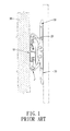
- Fig. 1 shows a conventional display bracket disclosed by the Taiwan Patent # M303314 , which is entitled "Adjustable Hinge for a Display.”
- the display bracket comprises a pair of bases 10 and a pair of adjusting assemblies 20 connected thereto, with the figure only showing one of each.
- Each of the adjusting assembly 20 includes a connection rod 21, an attachment rod 22, and four arms 23 (the figure only shows two of the four arms).
- the preceding parts are pivotally connected with each other in forming a trapezoidal four-bar linkage.
- the attachment rod 22 can be inclined upward or downward at various angles.
- the display can not be retracted by the bracket to save space.
- the position of the attachment rod 22 relative to the connection rod 21 is fixed sideways. Such configuration means the display can not shift sideways relative to the wall 30 and causes inconvenience to the users.
- US 2007/0120032 relates to a mounting assembly for a flat panel video display.
- the mounting assembly is further equipped with a locking mechanism being received within a curved slot for stepless adjustments and thus holding the front and back plates in position. Conceivably, it not only needs redundant components, but also results in poor reliability and complicated operations.
- US 2007/0290588 relates to a display unit installing structure for a refrigerator.
- the structure includes linkage rods moving in a symmetrical manner to drive the display departing from the refrigerator.
- One aspect of the instant disclosure is to provide an adjustable display mounting bracket assembly
- the assembly offers space-saving advantage and sideways adjustment capability for the mounted display.
- the assembly comprises a mounting bracket, at least one linkage unit, and a fixing plate.
- the mounting bracket has a main body, at least one first connecting member, at least one second connecting member, a support body, and at least one fastening means.
- the main body includes at least one first fixing portion and at least one second fixing portion.
- the first connecting member has a first end portion and a second end portion formed oppositely thereon. The first end portion of the first connecting member is pivotally connected to the first fixing portion of the main body for pivoting about a first axis.
- the second connecting member has a first end portion and a second end portion formed oppositely thereon. A sliding slot is formed on the first end portion of the second connecting member.
- the sliding slot has a first end defined near the second end portion of the second connecting member and a second end defined oppositely.
- the fastening means is projected through the sliding slot to pivotally connect the first end portion of the second connecting member with the second fixing portion of the main body.
- the second connecting member is pivotable around a second axis.
- the support body has at least one first connecting portion and at least one second connecting portion.
- the first connecting portion is pivotally connected to the second end portion of the first connecting member and pivotable around a third axis.
- the second connecting portion is pivotally connected to the second end portion of the second connecting member and pivotable around a fourth axis.
- the first end portion of the second connecting member is slidable with respect to the second fixing portion. In this manner, the distance between the second and fourth axes can be adjusted.
- the distance between the second and fourth axes is the shortest.
- the distance is the longest.
- the fixing plate is used for securing the assembly to a mounting surface, such as a wall.
- the linkage unit is pivotally connected to the fixing plate on one end and pivotally connected to the mounting bracket on opposite end. The linkage unit serves to adjust the distance between the mounting bracket and the fixing plate.
- the support body has a base A first supporting wall and a second supporting wall are formed perpendicularly on respective opposite sides of the base.
- the first supporting wall has at least one first shaft hole formed thereon, and the second supporting wall has at least one second shaft hole formed thereon correspondingly.
- the linkage unit further includes a shaft, a first connecting arm, a connecting shaft, and a second connecting arm. The two opposite ends of the shaft project through the first and second shaft holes respectively.
- the first connecting arm is pivotally connected to the shaft on one end and pivotally connected to the connecting shaft on opposite end.
- the second connecting arm is pivotally connected to the connecting shaft on one end and pivotally connected to the fixing plate on opposite end.
- the distance between the first and second axes is denoted as A.
- the distance between the first and third axes is denoted as B.
- the distance between the third and fourth axes is denoted as C, and the shortest distance between the second and fourth axes is denoted as D.
- distance A would be less than the sum of distances B, C, and D.
- the first and second connecting members each resemble a rocker arm, while the support body acts as a fixed rod.
- the main body has a base plate and at least one side plate extending perpendicularly thereof.
- the first and second fixing portions are formed at opposing respective ends of the side plate.
- the support body has a base, wherein the first and second supporting walls are formed perpendicularly on respective sides of the base oppositely.
- the first connecting portions are arranged perpendicularly on the respective end portions of the first supporting wall oppositely.
- the second connecting portions are arranged perpendicularly on the respective end portions of the second supporting wall oppositely.
- the distance between the second and fourth axes is the least.
- the mounting bracket collapses as the base of the support body touches the base plate of the main body parallelly.
- the first fixing portion has a fixing hole formed thereon
- the second fixing portion has a through hole formed thereon.
- Each first connecting portion of the support body has a first through hole formed thereon
- each second connecting portion has a second through hole formed thereon.
- a first hole and a second hole are formed on the first end portion and the second end portion of the first connecting member, respectively.
- An aligning hole is formed on the second end portion of the second connecting member.
- a blocking portion is defined on the edge portion of the first end portion of the first connecting member.
- a stopping portion is defined on the edge portion of the second connecting portion of the support body.
- the fastening means includes at least one first fastening member.
- the first fastening member has at least one locking piece, at least one first torque-adjusting washer, at least one second torque-adjusting washer, at least one lock washer, and a nut.
- the first fastening member is projected inwardly through a locking hole formed on the locking piece, the first torque-adjusting washer, the second torque-adjusting washer, two lock washers, and the nut.
- the assembly may include at least one support link, and the fastening means may further include at least one second fastening member.
- the support link has a first end portion with a first securing hole formed thereon.
- the second fastening member has a threaded body projected through the second hole of the first connecting member, the first through hole of the first connecting portion of the support body, and the first securing hole of the support link.
- the assembly may include at least one spacer.
- a second end portion is defined on the support link opposite of the first end portion.
- a second securing hole is formed on the second end portion.
- the spacer is disposed between the first end portion of the first connecting member and the second end portion of the support link. The spacer is aligned with the first hole of the first connecting member and the second securing hole of the support link.
- the first fastening member is projected through the locking piece, the first fixing portion of the main body, the first end portion of the first connecting member, the spacer, the second end portion of the support link, and the nut.
- the assembly can further include at least one sleeve
- the fastening means can further include at least one third fastening member.
- the third fastening member has a threaded body, which is driven through the aligning holes 1312 of the second connecting members and the second through holes of the second connecting portions.
- the sleeve is fitted over the third fastening member between the two second connecting portions. The opposite ends of the sleeve face the respective inner surfaces of the second connecting members adjacent to the second connecting portions.
- the display can be mounted onto the adjustable mounting bracket, wherein the linkage unit is pivotally connected to the mounting bracket and the fixing plate on respective ends oppositely.
- the connecting shaft of the linkage unit is chosen as the pivot point
- the display can move toward or away from the fixing plate, or even moving diagonally with respect to the fixing plate.
- the shaft of the linkage unit is chosen as the pivot point
- the display can pivot on the linkage unit accordingly.
- the mounting bracket is adjusted to the greatest extent, i.e., at the trapezoidal position
- the display can be inclined upward or downward with respect to the linkage unit.
- the adjustable mounting bracket assembly of the instant disclosure allows adjustment of the viewing angle of the display and its position.
- the mounting bracket can be collapsed and the assembly itself can be pivoted so as to reduce the space taken up by the display/mounting bracket assembly.
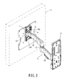
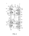
- FIGs. 2 , 3 , and 4 show an adjustable display mounting bracket assembly of the instant disclosure.
- the assembly comprises: an adjustable mounting bracket 1; a fixing plate 3 (for securing to a mounting surface such as a wall); and a linkage unit 2 pivotally connected between the mounting bracket 1 and the fixing plate 3.
- the mounting bracket 1 is used for securing a connecting plate (such as a vesa, not labeled), which secures a display 5.
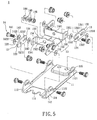
- the mounting bracket 1 includes a main body 11, two first connecting members 12, two second connecting members 13, eight fastening members, and a support body 15.
- any of the eight fastening member can be a first fastening member 14.
- the main body 11 has a flat base plate 111 and two opposing side plates 112 arranged perpendicularly on the base plate 111.
- a first fixing portion 114 and a second fixing portion 115 are formed on opposite ends of each side plate 112.
- a fixing hole 1122 is formed on each first fixing portion 114, and a through hole 1121 is formed on each second fixing portion 115.
- each first connecting member 12 has a flat first slab 121.
- the first slab 121 has a first end portion 123 and a second end portion 124 formed oppositely.
- a first hole 1211 is formed on the first end portion 123, and a second hole 1212 is formed on the second end portion 124.
- One first fastening member 14 is projected through the first hole 1211 and the corresponding fixing hole 1122, thus allowing the first connecting member 12 to be rotatable around a first axis L1 and pivotal on the side plate 112 of the main body 11.
- a sloped blocking portion 122 is formed on the edge of the first end portion 123, with additional details given later.
- each second connecting member 13 has a flat second slab 131.
- the second slab 131 has a first end portion 133 and a second end portion 134 formed oppositely.
- a sliding slot 1311 is formed on the first end portion 133, and an aligning hole 1312 is formed on the second end portion 134.
- one first fastening member 14 is projected through the sliding slot 1311 and the through hole 1121, thus enabling the second connecting member 13 to be rotatable around a second axis L2 and pivotal on the side plate 112 of the main body 11.
- the sliding slot 1311 is ovally shaped with a first end 1313 and a second end 1314.
- the sliding slot 1311 is extending substantially in the direction of the long axis of the second connecting member 13.
- the first end 1313 is formed in proximity to the aligning hole 1312, and the second end 1314 is formed away from the aligning hole 1312.
- the first fastening member 14 can slide between the first and second ends 1313 and 1314.
- each second connecting member 13 and corresponding first fastening member 14 can slide relative to each other in a direction perpendicularly to the second axis L2. More details will be provided later.
- the support body 15 has a flat base 151.
- a first supporting wall 152 and a second supporting wall 153 are perpendicularly arranged on the side portions of the base 151 opposingly.
- Two opposing first connecting portions 154 are perpendicularly arranged on the ends of the first supporting wall 152.
- two opposing second connecting portions 155 are perpendicularly arranged on the ends of the second supporting wall 153.
- An inclined stopping portion 1552 is formed on the edge of each second connecting portion 155.
- a first through hole 1541 is formed on each first connecting portion 154.
- One first fastening member 14 is used to project through the first through hole 1541 and the second hole 1212 of the corresponding first connecting member 12. Thereby, the support body 15 can rotate around a third axis L3 and pivot relative to the first connecting members 12.
- a second through hole 1551 is formed on each second connecting portion 155.
- one first fastening member 14 is used to project through each second through hole 1551 and the aligning hole 1312 of the corresponding second connecting member 13. Thereby, the support body 15 can rotate about a fourth axis L4 and pivot relative to the second connecting members 13.
- a first shaft hole 1521 is further formed on the first supporting wall 152.
- a second shaft hole 1531 is formed on the second supporting wall 153.
- the linkage unit 2 comprises a shaft 4, a first connecting arm 22, a connecting shaft 21, and a second connecting arm 23.
- the respective ends of the shaft 4 are secured by the first and second shaft holes 1521 and 1531.
- the first connecting arm 22 is connected pivotally to the shaft 4 on one end and to the upper portion of the connecting shaft 21 on the opposite end.
- the second connecting arm 23 is connected pivotally to the fixing plate 3 on one end and to the lower portion of the connecting shaft 21 on the opposite end. Therefore, the display 5 has more degrees of freedom.
- the mounting bracket 1 operates between a maximum adjusting position and a collapsed position.
- the maximum adjusting position of the mounting bracket 1 is illustrated in Fig. 6 . It is shown that the first fastening member 14 is slid to the second end 1314 (referring to Fig. 5 ) of the sliding slot 1311 of the second connecting member 13. At such instant, a trapezoidal four-bar linkage of pivotally connected main body 11, the first connecting member 12, the second connecting member 13, and the support body 15 is constructed.
- the main body 11, the support body 15, the first connecting member 12 and the second connecting member 13 are the baseline, the top line, and the sides of the trapezoid, respectively. Among them, the main body 11 is the longest. However, the construction is not restricted to the above.
- the distance between the first axis L1 and the second axis L2 is denoted as A
- the distance between the first axis L1 and the third axis L3 is denoted as B
- the distance between the third axis L3 and the fourth axis L4 is C
- the distance between the second axis L2 and the fourth axis L4 is D.
- the sum of B, C, and D is greater than A (A ⁇ B + C + D).
- the four-bar linkage structure is a double rocker mechanism, wherein the first and second connecting members 12 and 13 are rockers, and the support body 15 acts as the fixed link. This mechanism allows angular adjustments between the support body 15 and the main body 11. Additional details will be given hereinafter.
- the first fastening member 14 is slid to the first end 1313 ( Fig. 5 ) of the sliding slot 1311 of the second connecting member 13.
- the distance D between the second axis L2 and the fourth axis L4 is shortest, while the distances A, B, and C remain the same.
- the base 151 of the support body 15 parallelly fits the base plate 111 of the main body 11.
- no angular adjustment is allowable between the support body 15 and the main body 11.
- first fastening member 14 is not at either the first end 1313 or the second end 1314, but rather at the middle of the sliding slot 1311, external forces can still be applied to make angular adjustments between the base 151 and the base plate 111.
- the degree of the adjustment is relatively smaller.
- an angle A2 is formed between the base 151 and the base plate 111.
- A2 is the largest upward inclination angle of the mounting bracket 1.
- the display 5 can be inclined upward relative to the linkage unit 2.
- a downward & leftward force is applied to the second supporting wall 153 of the support body 15.
- the applied force causes the second connecting members 13 to slide with respect to the first fastening members 14.
- the second end portion 124 is driven to pivot downward.
- the base 151 of the support body 15 approaches the base plate 111 of the main body 11.
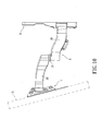
- the base 151 of the support body 15 would parallelly fit the base plate 111 of the main body 11. In this manner, the occupied space at the collapsed position is minimized.
- the mounting bracket 1 (or display 5) can pivot clockwise or counter-clockwise with respect to the linkage unit 2 (as shown by the arrows in Fig. 13 ).
- the mounting bracket 1 (or display 5) can move away or toward the fixing plate 3 (as shown by the arrows in Fig. 14 ).
- the mounting bracket 1 (or display 5) can diagonally shift with respect to the fixing plate 3 as shown in Fig. 15 . In other words, there is almost no dead angle when adjusting.
- first and second connecting arms 22 and 23 have approximately equal lengths, when both are pivoted toward the fixing plate 3, the mounting bracket 1 is pulled very close to the fixing plate 3, with a very short distance separating the two. In fact, they can touch each other.
- the mounting bracket 1 can be completely collapsed, with the base 151 parallelly fitting the base plate 111, the display 5, if not in use, can be maneuvered such that the occupied space is effectively reduced.
- Each fastening member 14 has a threaded body 141, a locking piece 142, a first lock washer 143, a second lock washer 144, two torque-adjusting washers 145, and a nut 146.
- Two engaging openings (not labeled) are formed on respective sides of the second hole 1212 of each first connecting member 12 oppositely.
- a locking hole 1421 is formed centrally on the locking piece 142.
- Two protrusions 1422 are formed on respective sides of the locking piece 142 oppositely. The protrusions 1422 are used for engaging to the respective engaging openings of the corresponding first connecting member 12.
- the first lock washer 143 and the second lock washer 144 are disposed on respective sides of the first through hole 1541 of the corresponding first connecting portion 154 oppositely.
- the first and second lock washers 143 and 144 are aligned with the second hole 1212 of the first connecting member 12.
- the threaded body 141 projects through the locking hole 1421 of the locking piece 142, the second hole 1212 of the first connecting member 12, the first lock washer 143, the first through hole 1541 of the first connecting portion 154, the second lock washer 144, two torque-adjusting washers 145, and the nut 146.
- each first fastening member 14 can be tightened or loosened based on needs. Thereby, the torque distribution between the first connecting members 12 and the support body 15 can be adjusted. Thus, damages due to wear and tear can be reduced.
- the locking hole 1421 of the locking piece 142, the second hole 1212 of the first connecting member 12, the first and second lock washers 143 and 144, and the two torque-adjusting washers 145 can be chosen accordingly to fit with the threaded body 141.
- the number and shape of the torque-adjusting washers and lock washers can be varied without restriction.
- a connecting plate (not labeled).
- the display 5 is bolted to the connecting plate, which is selected based on the size of the display 5.
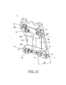
- the fastening means of the instant embodiment can further include at least one second fastening member 17 and at least one third fastening member 18, which are illustrated in Figs. 7 and 8 . Additional details are given below.
- the mounting bracket 1' further includes a pair of support links 16.
- the purpose is to bolster the tightness of the corresponding fastening members, such that the fastening members do not come loose while the mounting bracket 1' is being adjusted
- Each support link 16 has a first end portion 161 having a first securing hole 1611 formed thereon.
- the second fastening member 17 is a socket head cap screw, which is driven through the second hole 1212 of the first connecting member 12, the first through hole 1541 of the first connecting portion 154 of the support body 15, and the first securing hole 1611 of the support link 16.
- the instant embodiment further includes a pair of spacers 147.
- a second end portion 162 is defined on each support link 16 opposite of the first end portion 161.
- a second securing hole 1621 is formed on the second end portion 162.
- Each spacer 147 is disposed between the corresponding first end portion 123 of the first connecting member 12 and the second end portion 162 of the support link 16.
- the tubular-shaped spacers 147 are aligned with the first holes 1211 of the first connecting members 12 and the second securing holes 1621 of the support links 16. Specifically, one first fastening member 14 is projected through the corresponding first fixing portion 114, the first end portion 123 of the first connecting member 12, the spacer 147, and the second end portion 162 of the support link 16 in sequence.
- the instant embodiment includes a sleeve 6.
- the third fastening member 18 is a screw, which is driven through the aligning holes 1312 of the second connecting members 13 and the second through holes 1551 of the second connecting portions 155 of the support body 15.
- the sleeve 6 is fitted over the third fastening member 18 between the second connecting portions 155.
- the opposite ends of the sleeve 6 face toward the respective inner surfaces of the second connecting members 13 adjacent to the second connecting portions 155.
- the third fastening member 18 can be a longer socket head cap screw.
- the use of the first fastening members 14, the second fastening members 17, and the third fastening member 18 for the mounting bracket 1' only shows a preferable fastening means for the instant embodiment.
- the actual fastening means for the mounting bracket can be varied based on needs.
- the mounting bracket can use the first fastening members 14 only as in the first embodiment, or any combination of the first fastening member 14, the second fastening member 17, and the third fastening member 18.
- the locations of the support links 16 are not restricted. Namely, the support links 16 can be selectively disposed according to the selected fastening means with respect to the first, second, and third fastening members. The number, type, and the location of the abovementioned fasteners and support links 16 are not restricted.
- Fig. 17 shows a third embodiment of the instant disclosure.
- the third embodiment is similar to the previous embodiments.
- the linkage unit 2 has two first connecting arms 22, two connecting shafts 21, and two second connecting arms 23.
- each first connecting arm 22, connecting shaft 21, and second connecting arm 23 constitute one linkage set. Namely, there are one left linkage set and one right linkage set respectively.
- the connecting means with the mounting bracket 1 and the fixing plate 3 is the same as the previous embodiments, therefore is not repeated herein.
- the linkage unit 2 of the third embodiment is also the same as the previous embodiments.
- the mounting bracket assembly has greater support strength and is able to hold heavier displays.
- the display can be mounted to the adjustable mounting bracket, wherein the linkage unit is pivotally connected to the mounting bracket and the fixing plate on opposite ends.
- the connecting shaft of the linkage unit is chosen as the pivot point
- the display can shift toward or away from the fixing plate, or moving diagonally with respect to the fixing plate.
- the shaft of the linkage unit is chosen as the pivot point
- the display can pivot on the linkage unit accordingly.
- the mounting bracket is adjusted to the greatest extent, i.e., at the trapezoidal position
- the display can be inclined upward or downward with respect to the linkage unit.
Landscapes
- Engineering & Computer Science (AREA)
- General Engineering & Computer Science (AREA)
- Mechanical Engineering (AREA)
- Devices For Indicating Variable Information By Combining Individual Elements (AREA)
- Pivots And Pivotal Connections (AREA)
Claims (12)
- Einstellbare Halterung für eine Anzeigevorrichtung zum Anbau an eine Anbaufläche umfassend:eine Halterung (1), umfassend:einen Hauptkörper (11) mit mindestens einem ersten Befestigungsabschnitt (114) und mindestens einem zweiten Befestigungsabschnitt (115);mindestens ein erstes Verbindungsglied (12) mit einem ersten Endabschnitt (123) und einem gegenüberliegenden zweiten Endabschnitt (124), wobei der erste Endabschnitt (123) des ersten Verbindungsglieds (12) drehbar mit dem ersten Verbindungsabschnitt (114) des Hauptkörpers (11) und drehbar um eine erste Achse (L1) verbunden ist;mindestens ein zweites Verbindungsglied (13) mit einem ersten Endabschnitt (133) und einem gegenüberliegenden zweiten Endabschnitt (134);einen Stützkörper (15) mit mindestens einem ersten Verbindungsabschnitt (154) und mindestens einem zweiten Verbindungsabschnitt (155), wobei der erste Verbindungsabschnitt (154) drehbar mit dem zweiten Endabschnitt (124) des ersten Verbindungsglieds (12) und drehbar um eine dritte Achse (L3) verbunden ist und der zweite Verbindungsabschnitt (155) drehbar mit dem zweiten Endabschnitt (134) des zweiten Verbindungsglieds (13) und drehbar um eine vierte Achse (L4) verbunden ist;eine Befestigungsplatte (3) zur Befestigung an der Anbaufläche;und mindestens eine Verbindungseinheit (2), die drehbar die Befestigungsplatte (3) an einem Ende und drehbar die Halterung (1) am anderen Ende verbindet und die relative Position zwischen der Halterung (1) und der Anbauplatte (3) durch die Verbindungseinheit (2) einstellbar ist, dadurch gekennzeichnet, dass der erste Endabschnitt (133) des zweiten Verbindungsglieds (13) einen daran ausgebildeten in Wesentlichen sich in Richtung der Längsachse des zweiten Verbindungsglieds (13) erstreckenden länglichen Gleitschlitz (1311) aufweist, wobei der Gleitschlitz (1311) ein erstes Ende (1313), das sich in der Nähe des zweiten Endabschnitts (134) des zweiten Verbindungsglieds (13) befindet, und ein gegenüberliegendes zweites Ende (1314) aufweist;mindestens ein Befestigungsmittel, das durch den Gleitschlitz (1311) führend angeordnet ist, um den ersten Endabschnitt (133) des zweiten Verbindungsglieds (13) mit dem zweiten Befestigungsabschnitt (115) des Hauptkörpers (11) drehbar zu verbinden, damit das zweite Verbindungsglied (13) um eine zweite Achse (L2) drehbar ist; und wobei der erste Endabschnitt (133) des zweiten Verbindungsglieds (13) verschiebbar zum zweiten Befestigungsabschnitt (115) zur Änderung des relativen Abstands zwischen der zweiten Achse (L2) und der vierten Achse (L4) ist, wobei der Abstand zwischen der zweiten Achse (L2) und der vierten Achse (L4) am kürzesten ist, wenn sich das Befestigungsmittel in Richtung des ersten Endes (1313) des Gleitschlitzes (1311) bewegt, wobei der Abstand zwischen der zweiten Achse (L2) und der vierten Achse (L4) am längsten ist, wenn sich das Befestigungsmittel in Richtung zweites Ende (1314) des Gleitschlitzes (1311) bewegt.
- Eine einstellbare Halterung für eine Anzeigevorrichtung nach Anspruch 1, wobei der Stützkörper (15) ein tragendes Teil (151), eine erste Stützwand (152) und eine zweite Stützwand (153) umfasst, die erste Stützwand (152) und die zweite Stützwand (153) rechtwinklig an gegenüberliegenden Kanten des tragenden Teils (151) angeordnet sind, mindestens eine erste Wellenöffnung (1521) an der ersten Stützwand (152) ausgebildet ist, mindestens eine zweite Wellenöffnung (1531) entsprechend an der zweiten Stützwand (153) ausgebildet ist, wobei die Verbindungseinheit (2) ferner eine Welle (4), einen ersten Verbindungsarm (22), eine Verbindungswelle (21) und einen zweiten Verbindungsarm (23) umfasst, die gegenüberliegenden Enden der Welle (4) durch die erste Wellenöffnung (1521) und die zweite Wellenöffnung (1531) geführt sind, der erste Verbindungsarm (22) an einem Ende drehbar mit der Welle (4) und am anderen Ende drehbar an der Verbindungswelle (21) am gegenüberliegenden Ende und der zweite Verbindungsarm (23) drehbar an einem Ende an der Verbindungswelle (21) und am gegenüberliegenden Ende drehbar mit der Befestigungsplatte (3) verbunden sind.
- Eine einstellbare Halterung für eine Anzeigevorrichtung nach Anspruch 1, wobei der Abstand zwischen der ersten Achse (L1) und der zweiten Achse (L2) als A definiert ist, der Abstand zwischen der ersten Achse (L1) und der dritten Achse (L3) als B definiert ist, der Abstand zwischen der dritten Achse (L3) und der vierten Achse (L4) als C definiert ist, der Abstand zwischen der zweiten Achse (L2) und der vierten Achse (L4) als D definiert ist, wobei A die Summe aus B, C und D ist, wenn das Befestigungsmittel zum ersten Ende (1313) des Gleitschlitzes (1311) geschoben wird.
- Eine einstellbare Halterung für eine Anzeigevorrichtung nach Anspruch 3, wobei A weniger ist als die Summe aus B, C und D, wenn das Befestigungsmittel nicht am ersten Ende des Gleitschlitzes (1311) ist, wobei ein Doppelhebelmechanismus durch den Hauptkörper (11), das erste Verbindungsglied (12), das zweite Verbindungsglied (13) und den Stützkörper (15) gebildet wird, das erste Verbindungsglied (12) und das zweite Verbindungsglied (13) jeweils einen Hebel des Doppelhebelmechanismus bilden und der Stützkörper (15) eine feste Verbindung ist.
- Eine einstellbare Halterung für eine Anzeigevorrichtung nach Anspruch 4, wobei der Hauptkörper (11) eine Grundplatte (111) und mindestens eine Seitenplatte (112) aufweist, die rechtwinklig an den Kanten davon ausgebildet ist, der erste Befestigungsabschnitt (114) und der zweite Befestigungsabschnitt (115) an den entsprechenden Enden der Seitenplatte (112) gegenüberliegend ausgebildet sind, wobei der Stützkörper (15) eine Grundplatte (151), eine erste Stützwand (152) und eine zweite Stützwand (153), die rechtwinklig an den entsprechenden Kanten davon gegenüberliegend angeordnet ist, aufweist, einen ersten Verbindungsabschnitt (154), der rechtwinklig an beiden gegenüberliegenden Kanten der ersten Stützwand (152) angeordnet ist, einen zweiten Verbindungsabschnitt (155), der rechtwinklig an beiden gegenüberliegenden Kanten der zweiten Stützwand (153) angeordnet ist, aufweist, der Abstand zwischen der zweiten Achse (L2) und der vierten Achse (L4) am längsten ist, wenn die Befestigungsmittel am zweiten Ende (1314) des Gleitschlitzes (1311) für eine maximale Einstellung zwischen der Grundplatte (111) des Hauptkörpers (11) und dem tragenden Teil (151) des Stützkörpers (15) sind.
- Eine einstellbare Halterung für eine Anzeigevorrichtung nach Anspruch 5, wobei der Abstand zwischen der zweiten Achse (L2) und der vierten Achse (L4) am kürzesten ist, wenn das Befestigungsmittel am ersten Ende (1313) des Gleitschlitzes (1311) ist, wobei die Grundplatte (111) des Hauptkörpers (11) parallel zur Grundplatte (151) des Stützkörpers (15) steht.
- Eine einstellbare Halterung für eine Anzeigevorrichtung nach Anspruch 6, wobei eine Befestigungsbohrung (1122) am ersten Befestigungsabschnitt (114) und eine Durchgangsbohrung (1121) am zweiten Befestigungsabschnitt (115) ausgebildet sind, eine erste Durchgangsbohrung (1541) am ersten Verbindungsabschnitt (154) und eine zweite Durchgangsbohrung (1551) am zweiten Verbindungsabschnitt (155) ausgebildet sind, eine erste Bohrung (1211) am ersten Endabschnitt (123) des ersten Verbindungsglieds (12) und eine zweite Bohrung (1212) am zweiten Endabschnitt (124) des ersten Verbindungsglieds (12) ausgebildet sind, eine Ausrichtbohrung (1312) am zweiten Endabschnitt (134) des zweiten Verbindungsglieds (13) ausgebildet ist, die Befestigungsmittel durch die erste Durchgangsbohrung (1541), die zweite Bohrung (1212), die zweite Durchgangsbohrung (1551), die Ausrichtbohrung (1312), die Befestigungsbohrung (1122), die erste Bohrung (1211), die Durchgangsbohrung (1121) und den Gleitschlitz (1311) geführt sind, um den Hauptkörper (11), das erste Verbindungsglied (12), das zweite Verbindungsglied (13) und den Stützkörper (15) drehbar zu verbinden.
- Eine einstellbare Halterung für eine Anzeigevorrichtung nach Anspruch 7, wobei ein Sperrabschnitt (122) am ersten Endabschnitt (123) des ersten Verbindungsglieds (12) ausgebildet ist und wobei ein Stoppabschnitt (1552) am zweiten Verbindungsabschnitt (155) des Stützkörpers (15) ausgebildet ist.
- Eine einstellbare Halterung für eine Anzeigevorrichtung nach Anspruch 7, wobei das Befestigungsmittel mindestens ein erstes Befestigungsglied (14) umfasst, wobei das erste Befestigungsglied (14) mindestens ein Feststellteil (142), mindestens einen ersten Federring (143), mindestens einen zweiten Federring (144), mindestens eine drehmomenteinstellende Scheibe (145) und eine Mutter (146) umfasst und wobei das erste Befestigungsglied (14) durch eine Feststellbohrung (1421) des Feststellteils (142), den ersten Federring (143), den zweiten Federring (144), die drehmomenteinstellenden Scheiben (145) und die Mutter nach innen geschoben wird.
- Eine einstellbare Halterung für eine Anzeigevorrichtung nach Anspruch 9, ferner umfassend mindestens eine Stützverbindung (16), wobei das Befestigungsmittel ferner mindestens ein zweites Befestigungsglied (17) umfasst, die Stützverbindung (16) einen ersten Endabschnitt (161) mit einer ersten Befestigungsbohrung (1611) aufweist, die am ersten Endabschnitt (161) ausgebildet ist, und wobei das zweite Befestigungsglied (17) einen Gewindekörper (141) aufweist, der durch die zweite Bohrung (1212) des ersten Verbindungsglieds (12), die erste Durchgangsbohrung (1541) des ersten Verbindungsabschnitts (154) des Stützkörpers (15) und die erste Befestigungsbohrung (1611) der Stützverbindung (16) geführt wird.
- Eine einstellbare Halterung für eine Anzeigevorrichtung nach Anspruch 10, ferner umfassend mindestens ein Abstandsstück (147), wobei ein zweiter Endabschnitt (162) an der Stützverbindung (16) gegenüber dem ersten Endabschnitt (161) ausgebildet ist, eine zweite Befestigungsbohrung (1621) am zweiten Endabschnitt (162) der Stützverbindung (16) ausgebildet ist, das Abstandsstück (147) zwischen dem ersten Endabschnitt (123) des ersten Verbindungsglieds (12) und dem zweiten Endabschnitt (162) der Stützverbindung (16) angeordnet ist, das Abstandsstück (147) mit der ersten Bohrung (1211) des ersten Verbindungsglieds (12) und der zweiten Befestigungsbohrung (1621) der Stützverbindung (16) ausgerichtet ist, das erste Befestigungsglied (14) durch den ersten Befestigungsabschnitt (114) des Hauptkörpers (11), den ersten Endabschnitt (123) des ersten Verbindungsglieds (12), das Abstandsstück (147) und den zweiten Endabschnitt (162) der Stützverbindung (16) geführt wird.
- Eine einstellbare Halterung für eine Anzeigevorrichtung nach Anspruch 7, ferner umfassend mindestens eine Buchse (6), wobei das Befestigungsmittel ferner mindestens ein drittes Befestigungsglied (18) mit einen Gewindekörper (141) umfasst, das dritte Befestigungsglied (18) durch die zweiten Durchgangsbohrungen (1551) der gegenüberliegenden zweiten Verbindungsabschnitte (155) und die Ausrichtbohrungen (1312) der zweiten Verbindungsglieder (13) geführt wird, die Buchse (6) über dem dritten Befestigungsglied (18) zwischen den gegenüberliegenden zweiten Verbindungsabschnitten (155) angebracht ist und wobei die gegenüberliegenden Enden der Buchse (6) in Richtung der entsprechenden Innenflächen der zweiten Verbindungsglieder (13) neben den zweiten Verbindungsabschnitten (155) zeigen.
Applications Claiming Priority (1)
| Application Number | Priority Date | Filing Date | Title |
|---|---|---|---|
| TW100205179U TWM410827U (en) | 2011-03-23 | 2011-03-23 | Hanging base capable of regulating angle, and monitor fastening rack having hanging base capable of regulating angle |
Publications (3)
| Publication Number | Publication Date |
|---|---|
| EP2503209A2 EP2503209A2 (de) | 2012-09-26 |
| EP2503209A3 EP2503209A3 (de) | 2012-10-17 |
| EP2503209B1 true EP2503209B1 (de) | 2014-06-04 |
Family
ID=46418163
Family Applications (1)
| Application Number | Title | Priority Date | Filing Date |
|---|---|---|---|
| EP11170343.5A Not-in-force EP2503209B1 (de) | 2011-03-23 | 2011-06-17 | Einstellbare Anzeigehaltevorrichtung |
Country Status (4)
| Country | Link |
|---|---|
| US (1) | US8628051B2 (de) |
| EP (1) | EP2503209B1 (de) |
| JP (1) | JP3175332U (de) |
| TW (1) | TWM410827U (de) |
Families Citing this family (17)
| Publication number | Priority date | Publication date | Assignee | Title |
|---|---|---|---|---|
| CN103717958A (zh) * | 2011-05-19 | 2014-04-09 | 爱格升公司 | 显示器安装接口系统和将电子显示器安装到支座的方法 |
| US9004430B2 (en) * | 2011-09-30 | 2015-04-14 | Imperial Stamping Corporation | Articulating mount for a display |
| TWI482495B (zh) * | 2012-04-17 | 2015-04-21 | Wistron Corp | 可限制樞轉功能的顯示器 |
| CN104875688A (zh) * | 2014-02-28 | 2015-09-02 | 北京谊安医疗系统股份有限公司 | 显示器固定装置及具有它的车辆 |
| CN103939717B (zh) * | 2014-04-28 | 2017-01-18 | 乐歌人体工学科技股份有限公司 | 曲面电视壁挂架 |
| US9265346B1 (en) * | 2015-03-13 | 2016-02-23 | Anthony Eugene Forney | Responsive support system and mount |
| KR102341742B1 (ko) * | 2015-04-08 | 2021-12-22 | 삼성전자주식회사 | 디스플레이 장치 및 디스플레이 장치용 월 마운트 장치 |
| CN105805503B (zh) * | 2016-05-20 | 2018-09-18 | 广州钜盛金属制品有限公司 | 电控式前维护拼接架 |
| CN105967045A (zh) * | 2016-07-29 | 2016-09-28 | 孝感市卡普隆日用品有限公司 | 一种连接牢固的显示器吊装装置 |
| CN209012705U (zh) * | 2018-10-26 | 2019-06-21 | 苏州工业园区博汇工业品有限公司 | 用于电视支架的自锁机构及电视支架 |
| CN110925278B (zh) * | 2019-11-22 | 2024-09-17 | 广东乐思富科技有限公司 | 顶线连接件 |
| US12385598B2 (en) * | 2020-07-09 | 2025-08-12 | Barco N.V. | Alignment mechanism and methods for installation of tiled displays |
| CN114183659B (zh) * | 2020-09-15 | 2024-05-28 | 北京广利核系统工程有限公司 | 一种调节支架 |
| CN113503447A (zh) * | 2021-07-27 | 2021-10-15 | 深圳市倍思奇创新科技有限公司 | 角度调节机构及其电视安装支架 |
| US20240218968A1 (en) * | 2022-12-31 | 2024-07-04 | Izrael Bonds | Corner wall mount |
| US20240271744A1 (en) * | 2023-02-15 | 2024-08-15 | Weiping Cai | Adjustment component and multi-functional tv bracket |
| USD1092483S1 (en) * | 2023-10-16 | 2025-09-09 | Legrand Av Inc. | Television mount with single arm |
Family Cites Families (19)
| Publication number | Priority date | Publication date | Assignee | Title |
|---|---|---|---|---|
| GB1334522A (en) * | 1971-07-02 | 1973-10-17 | Dennard Ltd | Tiltable mountings for cameras or the like |
| GB9510740D0 (en) | 1995-05-26 | 1995-07-19 | Encomech Eng Services | Heat shields |
| US5924664A (en) * | 1997-03-12 | 1999-07-20 | Ergo View Technologies Corp. | Keyboard support mechanism |
| US6402109B1 (en) * | 2001-05-16 | 2002-06-11 | Chief Manufacturing, Inc. | Self-balancing mounting system for a flat panel display |
| US6533229B1 (en) * | 2001-12-14 | 2003-03-18 | Ray Hung | Adjustable keyboard tray for a desk |
| US6905102B2 (en) * | 2003-07-01 | 2005-06-14 | Puu Rong Industries Co., Ltd. | Keyboard support bracket structure |
| MX2007007603A (es) * | 2004-12-24 | 2007-08-02 | Lg Electronics Inc | Estructura de instalacion de unidad de despliegue para refrigerador. |
| US20080315049A1 (en) * | 2005-03-11 | 2008-12-25 | Omb S.R.L. | Mounting System for a Household Appliance |
| US20060291152A1 (en) * | 2005-06-06 | 2006-12-28 | Jeff Bremmon | Mounting device for flat-panel display |
| GB0516913D0 (en) * | 2005-08-18 | 2005-09-28 | Avf Group Ltd | Tilting mechanism |
| CN100589209C (zh) * | 2005-09-06 | 2010-02-10 | 全向装配系统公司 | 用于安装平板视频显示器的系统和方法 |
| US7641163B2 (en) * | 2005-10-21 | 2010-01-05 | Peerless Industries, Inc. | Tilt mounting system |
| US8028964B2 (en) * | 2006-01-13 | 2011-10-04 | Peerless Industries, Inc. | Incremental angular position and locking system for mounting devices |
| TWM303314U (en) | 2006-06-06 | 2006-12-21 | Chin-Jui Hung | Monitor fastening bracket capable of adjusting angle arbitrarily |
| TWM336658U (en) * | 2008-01-31 | 2008-07-11 | Ming-Hsien Huang | Screen supporting unit |
| KR100951999B1 (ko) * | 2009-01-15 | 2010-04-08 | 곽수만 | 디스플레이 틸팅장치 |
| US20120104204A1 (en) * | 2010-10-28 | 2012-05-03 | Chin-Jui Hung | Adjustable display screen hanging device |
| US20130048811A1 (en) * | 2011-08-30 | 2013-02-28 | Yi-Chen Tseng | A mounting kit |
| US8573551B2 (en) * | 2011-08-31 | 2013-11-05 | Modernsolid Industrial Co., Ltd. | Fine-adjusting apparatus for an overhead projector |
-
2011
- 2011-03-23 TW TW100205179U patent/TWM410827U/zh not_active IP Right Cessation
- 2011-06-17 EP EP11170343.5A patent/EP2503209B1/de not_active Not-in-force
- 2011-06-28 US US13/171,424 patent/US8628051B2/en active Active
-
2012
- 2012-02-15 JP JP2012000777U patent/JP3175332U/ja not_active Expired - Fee Related
Also Published As
| Publication number | Publication date |
|---|---|
| JP3175332U (ja) | 2012-05-10 |
| TWM410827U (en) | 2011-09-01 |
| US20120241578A1 (en) | 2012-09-27 |
| US8628051B2 (en) | 2014-01-14 |
| EP2503209A3 (de) | 2012-10-17 |
| EP2503209A2 (de) | 2012-09-26 |
Similar Documents
| Publication | Publication Date | Title |
|---|---|---|
| US8628051B2 (en) | Adustable display mounting bracket assembly | |
| US7690605B2 (en) | Support structure torque transfer function | |
| US7513474B2 (en) | Systems and methods for mounting flat panel video displays | |
| US7950613B2 (en) | Moveable mounting system | |
| US20160161045A1 (en) | Support assembly for a device | |
| US20070252056A1 (en) | Display Mounting Apparatus | |
| US20060261227A1 (en) | Universal mounting system for a flat panel display | |
| US20090050757A1 (en) | Mount System Adapted to Rotate and Extend a Monitor | |
| GB2481047A (en) | A mounting system for pivotally mounting a flat screen display | |
| WO2010080925A1 (en) | Display mount with adjustable position tilt axis | |
| CN101720482A (zh) | 具有可选择定位倾斜轴的装置挂载座 | |
| CN101026015A (zh) | 显示设备的支座 | |
| US12546435B2 (en) | High load display support system | |
| KR100596583B1 (ko) | 모니터장치 | |
| JP2002244570A (ja) | ディスプレイユニット及びディスプレイの設置装置 | |
| CN102121554A (zh) | 具有调整功能的固定架 | |
| CN201078792Y (zh) | 可垂直升降的支撑结构 | |
| KR100765242B1 (ko) | 평판형 tv용 벽걸이식 거치대 | |
| US20050207101A1 (en) | Display device having an adjustable display screen | |
| KR200397713Y1 (ko) | 각도 및 거리조절 기능을 갖는 벽걸이형 텔레비젼의고정장치 | |
| EP1843077B1 (de) | Trägeranordnung für Bildschirme und ähnliche Geräte | |
| US20090065749A1 (en) | Supporting Structure Capable of Vertically Elevating | |
| JP2007108528A (ja) | 電気機器取付具 | |
| KR100784728B1 (ko) | 전방향 회전 가능한 디스플레이어 벽걸이장치 | |
| KR100838565B1 (ko) | 디스플레이 장치 회전용 스탠드 |
Legal Events
| Date | Code | Title | Description |
|---|---|---|---|
| PUAL | Search report despatched |
Free format text: ORIGINAL CODE: 0009013 |
|
| PUAI | Public reference made under article 153(3) epc to a published international application that has entered the european phase |
Free format text: ORIGINAL CODE: 0009012 |
|
| AK | Designated contracting states |
Kind code of ref document: A2 Designated state(s): AL AT BE BG CH CY CZ DE DK EE ES FI FR GB GR HR HU IE IS IT LI LT LU LV MC MK MT NL NO PL PT RO RS SE SI SK SM TR |
|
| AX | Request for extension of the european patent |
Extension state: BA ME |
|
| AK | Designated contracting states |
Kind code of ref document: A3 Designated state(s): AL AT BE BG CH CY CZ DE DK EE ES FI FR GB GR HR HU IE IS IT LI LT LU LV MC MK MT NL NO PL PT RO RS SE SI SK SM TR |
|
| AX | Request for extension of the european patent |
Extension state: BA ME |
|
| RIC1 | Information provided on ipc code assigned before grant |
Ipc: F16M 13/02 20060101ALI20120913BHEP Ipc: F16M 11/10 20060101AFI20120913BHEP Ipc: F16M 11/20 20060101ALI20120913BHEP |
|
| 17P | Request for examination filed |
Effective date: 20130204 |
|
| GRAP | Despatch of communication of intention to grant a patent |
Free format text: ORIGINAL CODE: EPIDOSNIGR1 |
|
| INTG | Intention to grant announced |
Effective date: 20140319 |
|
| GRAS | Grant fee paid |
Free format text: ORIGINAL CODE: EPIDOSNIGR3 |
|
| GRAA | (expected) grant |
Free format text: ORIGINAL CODE: 0009210 |
|
| AK | Designated contracting states |
Kind code of ref document: B1 Designated state(s): AL AT BE BG CH CY CZ DE DK EE ES FI FR GB GR HR HU IE IS IT LI LT LU LV MC MK MT NL NO PL PT RO RS SE SI SK SM TR |
|
| REG | Reference to a national code |
Ref country code: GB Ref legal event code: FG4D |
|
| REG | Reference to a national code |
Ref country code: CH Ref legal event code: EP |
|
| REG | Reference to a national code |
Ref country code: AT Ref legal event code: REF Ref document number: 671294 Country of ref document: AT Kind code of ref document: T Effective date: 20140615 |
|
| REG | Reference to a national code |
Ref country code: IE Ref legal event code: FG4D |
|
| REG | Reference to a national code |
Ref country code: DE Ref legal event code: R096 Ref document number: 602011007360 Country of ref document: DE Effective date: 20140717 |
|
| REG | Reference to a national code |
Ref country code: AT Ref legal event code: MK05 Ref document number: 671294 Country of ref document: AT Kind code of ref document: T Effective date: 20140604 |
|
| REG | Reference to a national code |
Ref country code: NL Ref legal event code: VDEP Effective date: 20140604 |
|
| PG25 | Lapsed in a contracting state [announced via postgrant information from national office to epo] |
Ref country code: NO Free format text: LAPSE BECAUSE OF FAILURE TO SUBMIT A TRANSLATION OF THE DESCRIPTION OR TO PAY THE FEE WITHIN THE PRESCRIBED TIME-LIMIT Effective date: 20140904 Ref country code: CY Free format text: LAPSE BECAUSE OF FAILURE TO SUBMIT A TRANSLATION OF THE DESCRIPTION OR TO PAY THE FEE WITHIN THE PRESCRIBED TIME-LIMIT Effective date: 20140604 Ref country code: LT Free format text: LAPSE BECAUSE OF FAILURE TO SUBMIT A TRANSLATION OF THE DESCRIPTION OR TO PAY THE FEE WITHIN THE PRESCRIBED TIME-LIMIT Effective date: 20140604 Ref country code: FI Free format text: LAPSE BECAUSE OF FAILURE TO SUBMIT A TRANSLATION OF THE DESCRIPTION OR TO PAY THE FEE WITHIN THE PRESCRIBED TIME-LIMIT Effective date: 20140604 Ref country code: GR Free format text: LAPSE BECAUSE OF FAILURE TO SUBMIT A TRANSLATION OF THE DESCRIPTION OR TO PAY THE FEE WITHIN THE PRESCRIBED TIME-LIMIT Effective date: 20140905 |
|
| REG | Reference to a national code |
Ref country code: LT Ref legal event code: MG4D |
|
| PG25 | Lapsed in a contracting state [announced via postgrant information from national office to epo] |
Ref country code: SE Free format text: LAPSE BECAUSE OF FAILURE TO SUBMIT A TRANSLATION OF THE DESCRIPTION OR TO PAY THE FEE WITHIN THE PRESCRIBED TIME-LIMIT Effective date: 20140604 Ref country code: RS Free format text: LAPSE BECAUSE OF FAILURE TO SUBMIT A TRANSLATION OF THE DESCRIPTION OR TO PAY THE FEE WITHIN THE PRESCRIBED TIME-LIMIT Effective date: 20140604 Ref country code: AT Free format text: LAPSE BECAUSE OF FAILURE TO SUBMIT A TRANSLATION OF THE DESCRIPTION OR TO PAY THE FEE WITHIN THE PRESCRIBED TIME-LIMIT Effective date: 20140604 Ref country code: LV Free format text: LAPSE BECAUSE OF FAILURE TO SUBMIT A TRANSLATION OF THE DESCRIPTION OR TO PAY THE FEE WITHIN THE PRESCRIBED TIME-LIMIT Effective date: 20140604 Ref country code: HR Free format text: LAPSE BECAUSE OF FAILURE TO SUBMIT A TRANSLATION OF THE DESCRIPTION OR TO PAY THE FEE WITHIN THE PRESCRIBED TIME-LIMIT Effective date: 20140604 |
|
| PG25 | Lapsed in a contracting state [announced via postgrant information from national office to epo] |
Ref country code: PT Free format text: LAPSE BECAUSE OF FAILURE TO SUBMIT A TRANSLATION OF THE DESCRIPTION OR TO PAY THE FEE WITHIN THE PRESCRIBED TIME-LIMIT Effective date: 20141006 Ref country code: EE Free format text: LAPSE BECAUSE OF FAILURE TO SUBMIT A TRANSLATION OF THE DESCRIPTION OR TO PAY THE FEE WITHIN THE PRESCRIBED TIME-LIMIT Effective date: 20140604 Ref country code: CZ Free format text: LAPSE BECAUSE OF FAILURE TO SUBMIT A TRANSLATION OF THE DESCRIPTION OR TO PAY THE FEE WITHIN THE PRESCRIBED TIME-LIMIT Effective date: 20140604 Ref country code: SK Free format text: LAPSE BECAUSE OF FAILURE TO SUBMIT A TRANSLATION OF THE DESCRIPTION OR TO PAY THE FEE WITHIN THE PRESCRIBED TIME-LIMIT Effective date: 20140604 Ref country code: ES Free format text: LAPSE BECAUSE OF FAILURE TO SUBMIT A TRANSLATION OF THE DESCRIPTION OR TO PAY THE FEE WITHIN THE PRESCRIBED TIME-LIMIT Effective date: 20140604 Ref country code: RO Free format text: LAPSE BECAUSE OF FAILURE TO SUBMIT A TRANSLATION OF THE DESCRIPTION OR TO PAY THE FEE WITHIN THE PRESCRIBED TIME-LIMIT Effective date: 20140604 |
|
| REG | Reference to a national code |
Ref country code: CH Ref legal event code: PL |
|
| PG25 | Lapsed in a contracting state [announced via postgrant information from national office to epo] |
Ref country code: PL Free format text: LAPSE BECAUSE OF FAILURE TO SUBMIT A TRANSLATION OF THE DESCRIPTION OR TO PAY THE FEE WITHIN THE PRESCRIBED TIME-LIMIT Effective date: 20140604 Ref country code: NL Free format text: LAPSE BECAUSE OF FAILURE TO SUBMIT A TRANSLATION OF THE DESCRIPTION OR TO PAY THE FEE WITHIN THE PRESCRIBED TIME-LIMIT Effective date: 20140604 Ref country code: IS Free format text: LAPSE BECAUSE OF FAILURE TO SUBMIT A TRANSLATION OF THE DESCRIPTION OR TO PAY THE FEE WITHIN THE PRESCRIBED TIME-LIMIT Effective date: 20141004 |
|
| REG | Reference to a national code |
Ref country code: DE Ref legal event code: R097 Ref document number: 602011007360 Country of ref document: DE |
|
| REG | Reference to a national code |
Ref country code: IE Ref legal event code: MM4A |
|
| PG25 | Lapsed in a contracting state [announced via postgrant information from national office to epo] |
Ref country code: MC Free format text: LAPSE BECAUSE OF FAILURE TO SUBMIT A TRANSLATION OF THE DESCRIPTION OR TO PAY THE FEE WITHIN THE PRESCRIBED TIME-LIMIT Effective date: 20140604 |
|
| PLBE | No opposition filed within time limit |
Free format text: ORIGINAL CODE: 0009261 |
|
| STAA | Information on the status of an ep patent application or granted ep patent |
Free format text: STATUS: NO OPPOSITION FILED WITHIN TIME LIMIT |
|
| PG25 | Lapsed in a contracting state [announced via postgrant information from national office to epo] |
Ref country code: CH Free format text: LAPSE BECAUSE OF NON-PAYMENT OF DUE FEES Effective date: 20140630 Ref country code: IE Free format text: LAPSE BECAUSE OF NON-PAYMENT OF DUE FEES Effective date: 20140617 Ref country code: IT Free format text: LAPSE BECAUSE OF FAILURE TO SUBMIT A TRANSLATION OF THE DESCRIPTION OR TO PAY THE FEE WITHIN THE PRESCRIBED TIME-LIMIT Effective date: 20140604 Ref country code: DK Free format text: LAPSE BECAUSE OF FAILURE TO SUBMIT A TRANSLATION OF THE DESCRIPTION OR TO PAY THE FEE WITHIN THE PRESCRIBED TIME-LIMIT Effective date: 20140604 Ref country code: LI Free format text: LAPSE BECAUSE OF NON-PAYMENT OF DUE FEES Effective date: 20140630 |
|
| 26N | No opposition filed |
Effective date: 20150305 |
|
| REG | Reference to a national code |
Ref country code: DE Ref legal event code: R097 Ref document number: 602011007360 Country of ref document: DE Effective date: 20150305 |
|
| PG25 | Lapsed in a contracting state [announced via postgrant information from national office to epo] |
Ref country code: BE Free format text: LAPSE BECAUSE OF FAILURE TO SUBMIT A TRANSLATION OF THE DESCRIPTION OR TO PAY THE FEE WITHIN THE PRESCRIBED TIME-LIMIT Effective date: 20140604 |
|
| PG25 | Lapsed in a contracting state [announced via postgrant information from national office to epo] |
Ref country code: SI Free format text: LAPSE BECAUSE OF FAILURE TO SUBMIT A TRANSLATION OF THE DESCRIPTION OR TO PAY THE FEE WITHIN THE PRESCRIBED TIME-LIMIT Effective date: 20140604 |
|
| REG | Reference to a national code |
Ref country code: FR Ref legal event code: PLFP Year of fee payment: 5 |
|
| PGFP | Annual fee paid to national office [announced via postgrant information from national office to epo] |
Ref country code: DE Payment date: 20150827 Year of fee payment: 5 Ref country code: GB Payment date: 20150826 Year of fee payment: 5 |
|
| PGFP | Annual fee paid to national office [announced via postgrant information from national office to epo] |
Ref country code: FR Payment date: 20150826 Year of fee payment: 5 |
|
| PG25 | Lapsed in a contracting state [announced via postgrant information from national office to epo] |
Ref country code: MT Free format text: LAPSE BECAUSE OF FAILURE TO SUBMIT A TRANSLATION OF THE DESCRIPTION OR TO PAY THE FEE WITHIN THE PRESCRIBED TIME-LIMIT Effective date: 20140604 |
|
| PG25 | Lapsed in a contracting state [announced via postgrant information from national office to epo] |
Ref country code: SM Free format text: LAPSE BECAUSE OF FAILURE TO SUBMIT A TRANSLATION OF THE DESCRIPTION OR TO PAY THE FEE WITHIN THE PRESCRIBED TIME-LIMIT Effective date: 20140604 |
|
| PG25 | Lapsed in a contracting state [announced via postgrant information from national office to epo] |
Ref country code: BG Free format text: LAPSE BECAUSE OF FAILURE TO SUBMIT A TRANSLATION OF THE DESCRIPTION OR TO PAY THE FEE WITHIN THE PRESCRIBED TIME-LIMIT Effective date: 20140604 |
|
| PG25 | Lapsed in a contracting state [announced via postgrant information from national office to epo] |
Ref country code: TR Free format text: LAPSE BECAUSE OF FAILURE TO SUBMIT A TRANSLATION OF THE DESCRIPTION OR TO PAY THE FEE WITHIN THE PRESCRIBED TIME-LIMIT Effective date: 20140604 Ref country code: HU Free format text: LAPSE BECAUSE OF FAILURE TO SUBMIT A TRANSLATION OF THE DESCRIPTION OR TO PAY THE FEE WITHIN THE PRESCRIBED TIME-LIMIT; INVALID AB INITIO Effective date: 20110617 Ref country code: LU Free format text: LAPSE BECAUSE OF NON-PAYMENT OF DUE FEES Effective date: 20140617 |
|
| REG | Reference to a national code |
Ref country code: DE Ref legal event code: R119 Ref document number: 602011007360 Country of ref document: DE |
|
| GBPC | Gb: european patent ceased through non-payment of renewal fee |
Effective date: 20160617 |
|
| REG | Reference to a national code |
Ref country code: FR Ref legal event code: ST Effective date: 20170228 |
|
| PG25 | Lapsed in a contracting state [announced via postgrant information from national office to epo] |
Ref country code: DE Free format text: LAPSE BECAUSE OF NON-PAYMENT OF DUE FEES Effective date: 20170103 Ref country code: FR Free format text: LAPSE BECAUSE OF NON-PAYMENT OF DUE FEES Effective date: 20160630 |
|
| PG25 | Lapsed in a contracting state [announced via postgrant information from national office to epo] |
Ref country code: GB Free format text: LAPSE BECAUSE OF NON-PAYMENT OF DUE FEES Effective date: 20160617 |
|
| PG25 | Lapsed in a contracting state [announced via postgrant information from national office to epo] |
Ref country code: MK Free format text: LAPSE BECAUSE OF FAILURE TO SUBMIT A TRANSLATION OF THE DESCRIPTION OR TO PAY THE FEE WITHIN THE PRESCRIBED TIME-LIMIT Effective date: 20140604 |
|
| PG25 | Lapsed in a contracting state [announced via postgrant information from national office to epo] |
Ref country code: AL Free format text: LAPSE BECAUSE OF FAILURE TO SUBMIT A TRANSLATION OF THE DESCRIPTION OR TO PAY THE FEE WITHIN THE PRESCRIBED TIME-LIMIT Effective date: 20140604 |