EP2503237B1 - Gasherd - Google Patents
Gasherd Download PDFInfo
- Publication number
- EP2503237B1 EP2503237B1 EP12160550.5A EP12160550A EP2503237B1 EP 2503237 B1 EP2503237 B1 EP 2503237B1 EP 12160550 A EP12160550 A EP 12160550A EP 2503237 B1 EP2503237 B1 EP 2503237B1
- Authority
- EP
- European Patent Office
- Prior art keywords
- central
- chamber
- gas oven
- oven according
- embodied
- Prior art date
- Legal status (The legal status is an assumption and is not a legal conclusion. Google has not performed a legal analysis and makes no representation as to the accuracy of the status listed.)
- Active
Links
- 239000002320 enamel (paints) Substances 0.000 claims description 3
- 230000015572 biosynthetic process Effects 0.000 claims 1
- 239000002184 metal Substances 0.000 claims 1
- 239000007789 gas Substances 0.000 description 38
- 239000007788 liquid Substances 0.000 description 8
- 238000002485 combustion reaction Methods 0.000 description 5
- 238000004140 cleaning Methods 0.000 description 4
- 238000009434 installation Methods 0.000 description 4
- 238000004519 manufacturing process Methods 0.000 description 4
- 238000010411 cooking Methods 0.000 description 2
- VNWKTOKETHGBQD-UHFFFAOYSA-N methane Chemical compound C VNWKTOKETHGBQD-UHFFFAOYSA-N 0.000 description 2
- 238000004080 punching Methods 0.000 description 2
- QVGXLLKOCUKJST-UHFFFAOYSA-N atomic oxygen Chemical compound [O] QVGXLLKOCUKJST-UHFFFAOYSA-N 0.000 description 1
- 239000000356 contaminant Substances 0.000 description 1
- 238000011109 contamination Methods 0.000 description 1
- 239000003915 liquefied petroleum gas Substances 0.000 description 1
- 239000003345 natural gas Substances 0.000 description 1
- 239000001301 oxygen Substances 0.000 description 1
- 229910052760 oxygen Inorganic materials 0.000 description 1
- 230000002093 peripheral effect Effects 0.000 description 1
- 238000007493 shaping process Methods 0.000 description 1
- 239000007787 solid Substances 0.000 description 1
- 238000006467 substitution reaction Methods 0.000 description 1
Images


Classifications
-
- F—MECHANICAL ENGINEERING; LIGHTING; HEATING; WEAPONS; BLASTING
- F23—COMBUSTION APPARATUS; COMBUSTION PROCESSES
- F23L—SUPPLYING AIR OR NON-COMBUSTIBLE LIQUIDS OR GASES TO COMBUSTION APPARATUS IN GENERAL ; VALVES OR DAMPERS SPECIALLY ADAPTED FOR CONTROLLING AIR SUPPLY OR DRAUGHT IN COMBUSTION APPARATUS; INDUCING DRAUGHT IN COMBUSTION APPARATUS; TOPS FOR CHIMNEYS OR VENTILATING SHAFTS; TERMINALS FOR FLUES
- F23L9/00—Passages or apertures for delivering secondary air for completing combustion of fuel
-
- F—MECHANICAL ENGINEERING; LIGHTING; HEATING; WEAPONS; BLASTING
- F23—COMBUSTION APPARATUS; COMBUSTION PROCESSES
- F23D—BURNERS
- F23D14/00—Burners for combustion of a gas, e.g. of a gas stored under pressure as a liquid
- F23D14/02—Premix gas burners, i.e. in which gaseous fuel is mixed with combustion air upstream of the combustion zone
- F23D14/04—Premix gas burners, i.e. in which gaseous fuel is mixed with combustion air upstream of the combustion zone induction type, e.g. Bunsen burner
- F23D14/06—Premix gas burners, i.e. in which gaseous fuel is mixed with combustion air upstream of the combustion zone induction type, e.g. Bunsen burner with radial outlets at the burner head
- F23D14/065—Premix gas burners, i.e. in which gaseous fuel is mixed with combustion air upstream of the combustion zone induction type, e.g. Bunsen burner with radial outlets at the burner head with injector axis inclined to the burner head axis
-
- F—MECHANICAL ENGINEERING; LIGHTING; HEATING; WEAPONS; BLASTING
- F24—HEATING; RANGES; VENTILATING
- F24C—DOMESTIC STOVES OR RANGES ; DETAILS OF DOMESTIC STOVES OR RANGES, OF GENERAL APPLICATION
- F24C15/00—Details
- F24C15/14—Spillage trays or grooves
-
- F—MECHANICAL ENGINEERING; LIGHTING; HEATING; WEAPONS; BLASTING
- F24—HEATING; RANGES; VENTILATING
- F24C—DOMESTIC STOVES OR RANGES ; DETAILS OF DOMESTIC STOVES OR RANGES, OF GENERAL APPLICATION
- F24C3/00—Stoves or ranges for gaseous fuels
- F24C3/08—Arrangement or mounting of burners
- F24C3/085—Arrangement or mounting of burners on ranges
-
- F—MECHANICAL ENGINEERING; LIGHTING; HEATING; WEAPONS; BLASTING
- F23—COMBUSTION APPARATUS; COMBUSTION PROCESSES
- F23D—BURNERS
- F23D2900/00—Special features of, or arrangements for burners using fluid fuels or solid fuels suspended in a carrier gas
- F23D2900/14—Special features of gas burners
- F23D2900/14062—Special features of gas burners for cooking ranges having multiple flame rings
Definitions
- the present invention belongs to the field of gas stoves.
- the present invention proposes a gas stove.
- a gas cooker embodied according to the invention comprises a cover plate and a burner, wherein the burner contains a gas mixing chamber, an outer burner cap and a central burner cap.
- the gas mixing chamber in turn comprises an outer chamber and a central chamber, wherein the outer burner cap is mounted on the outer chamber and the central burner cap on the central chamber.
- the gas cooker has a central drip which is located between the outer chamber and the central chamber and serves to collect and absorb drops falling between the outer chamber and the central chamber. Between the central drip and the outer chamber, a first gap is formed, which opens into the space below the cover plate and supplies the burner with secondary air from below the cover plate.
- a projection is formed, on which the central drip is placed.
- a projection is formed, on which the central drip is placed. This will on the one hand Saves manufacturing costs and on the other hand simplifies the installation and removal of the central drip for cleaning.
- a passage opening for the passage of the central chamber and / or an ignition electrode and / or a thermocouple is formed.
- an upward shaping is formed at the edge of the central drip.
- the central drip made of cold-rolled sheet is made with an enamel coating.
- a trim panel is present, which is located above the central drip and covering the first gap in a direction perpendicular to the cover plate, and that between the decorative panel and the central drip a second gap is formed, so that the secondary air through successively the first and the second gap is supplied to the burner.
- a trim panel is present, which is located above the central drip and covering the first gap in a direction perpendicular to the cover plate, and that between the decorative panel and the central drip a second gap is formed, so that the secondary air through successively the first and the second gap is supplied to the burner.
- an air outlet opening is formed in the trim panel, so that the secondary air is successively supplied to the burner through the first, the second gap and the air outlet opening.
- the problem that liquids often pass through this supply channel into the interior of the gas stove solved substantially from the ground up.
- the arrangement of the air outlet opening gives the gas stove a better overall look.
- the trim panel is designed circular disc-shaped and the air outlet opening is located in the middle of the trim panel.
- a peripheral side wall extends downwards on the outer edge of the trim panel.
- a projection is formed, on which the trim panel is placed.
- the trim panel and the central drip are made in one piece.
- the trim panel is designed inclined in the region of its air outlet opening to the central drip, whereby a liquid dripping onto the trim panel can be passed into the central drip.
- FIGS. 1 to 10 an embodiment of a gas stove according to the invention with a cover plate and a burner is shown, wherein the burner comprises a gas mixing chamber, an outer burner cap 1 and a central burner cap 2.
- the gas mixing chamber in turn comprises an outer chamber 3 and a central chamber 4, wherein the outer burner cap 1 is placed on the outer chamber 3 and the central burner cap 2 on the central chamber 4.
- the gas stove has a central drip 5, which is located between the outer chamber 3 and the central chamber 4 and serves to collect and absorb drops falling between the outer chamber 3 and the central chamber 4.
- the central drip 5 is made of cold-rolled sheet with an enamel coating.
- the central drip 5 and the outer chamber 3 are separated from each other by a first gap 9, which opens into the space below the cover plate and from there the burner supplies secondary air.
- FIG. 1 located between outer chamber 3 and central chamber 4, a connecting part 7 on which the central drip 5 is placed.
- On the connecting part 7 are also an ignition electrode and a thermocouple set up or to install.
- a through hole 12 for carrying out the central chamber 4, the ignition electrode and the thermocouple is formed.
- this is a common through hole 12, while in practice three through holes can be provided in each case for the central chamber 4, the ignition electrode and the thermocouple.
- an upward Anformung is formed, which forms a recess for receiving liquids together with the main body of the central drip 5.
- the central drip 5 is produced by punching.
- the gas stove additionally has a circular disc-shaped trim panel 6, which is located above the central drip 5.
- the trim 6 covers the first gap 9 from. That is, in a plan view of the burner, the first gap 9 is not visible, see FIG. 9 ,
- a circular air outlet 11 is formed in the middle.
- the trim panel 6 is spaced by a second gap 10 from the central drip 5, so that the secondary air is successively fed through the first gap 9, the second gap 10 and the air outlet opening 11 to the burner.
- Central chamber 4, ignition electrode and thermocouple are exposed through the air outlet opening 11.
- a projection 8 is formed, on which the trim plate 6 is placed.
- the trim panel 6 is made by punching.
- a projection on which the central drip is placed on the outer chamber facing the side wall of the central chamber.
- the projection on which the central drip is placed for example, on the side facing the central chamber of the outer chamber are located.
- a connecting part may be present to support the trim panel.
- the trim can also be made in one piece with the central drip.
- the trim panel can also be designed inclined in the region of its air outlet opening to the central drip.
- the trim panel may be multi-part, ie composed of two or more separate components.
Landscapes
- Engineering & Computer Science (AREA)
- Chemical & Material Sciences (AREA)
- Combustion & Propulsion (AREA)
- Mechanical Engineering (AREA)
- General Engineering & Computer Science (AREA)
- Gas Burners (AREA)
- Baking, Grill, Roasting (AREA)
Description
- Die vorliegende Erfindung gehört zum Bereich der Gasherde.
- Bei einem Brenner der bisher bekannten Gasherde sind in der Regel mehrere von innen nach außen verlaufende Brennstellenringe angeordnet. Dabei verhindern jedoch die Flammen am äußeren Brennstellenring, dass die Luft, deren Sauerstoffanteil für eine Verbrennung notwendig ist, in Richtung des inneren Brennstellenrings strömt, was schließlich zur unvollständigen Verbrennung bei den inneren Brennstellen führt. Um dies zu vermeiden, befindet sich bei herkömmlichen Gasherden an der Ober- oder Unterseite der Abdeckplatte meistens ein Nebenluftspalt zur Versorgung der inneren Brennstellen mit Luft. Im letzteren Fall treten beim Kochen oft Fremdkörper durch den Nebenluftspalt ins Innere des Gasherdes ein; welche Verschmutzungen darstellen und zugleich auch die Bauteile innerhalb des Geräts beschädigen können: Um dies zu vermeiden, ist es aus dem Stand der Technik bekannt, zwischen der äußeren und der zentralen Kammer ein Brennergitter vorzusehen. Mit einem solchen Brennergitter können zwar große Festkörper ferngehalten werden, der Nebenluftspalt und damit der Innenraum des Gasherdes sind jedoch flüssigen Verunreinigungen immer noch zugänglich. Mit anderen Worten liegt die genannte Problematik zumindest teilweise immer noch vor.
- Im Falle eines an der Oberseite der Abdeckplatte eines Gasherdes ausgebildeten Nebehluftspalts kann zwar keine Flüssigkeit durch den Nebenluftspalt ins Innere des Gasherdes eintreten, es können jedoch Tropfen zwischen der äußeren und der zentralen Kammer herunterfallen. Außerdem ist der Nebenluftspalt selbst verschmutzungsanfällig und nur schwer zu reinigen. Derartige Gasherde und Brenner für Gasherde sind beispielsweise aus den Dokumenten
CN 101178177 A ,CN 201187812 Y undWO2009078673 A2 . bekannt. - Die Beschreibung des Stands der Technik bedeutet nicht, dass der beschriebene Stand der Technik bereits vor dem Anmeldetag der vorliegenden Anmeldung dem Durchschnittsfachmann bekannt ist, sofern keine zureichenden Beweise dafür angeboten werden.
- Zur Lösung der oben erwähnten Probleme schlägt die vorliegende Erfindung einen Gasherd vor.
- Ein erfindungsgemäß ausgeführter Gasherd umfasst eine Abdeckplatte und einen Brenner, wobei der Brenner einen Gasmischraum, eine äußere Brennerkappe und eine zentrale Brennerkappe enthält. Der Gasmischraum umfasst wiederum eine äußere Kammer und eine zentrale Kammer, wobei die äußere Brennerkappe auf der äußeren Kammer und die zentrale Brennerkappe auf der zentralen Kammer aufgesetzt ist. Darüber hinaus verfügt der Gasherd über einen zentralen Tropfenfänger, der sich zwischen äußerer Kammer und zentraler Kammer befindet und zur Sammlung und Aufnahme von zwischen äußerer Kammer und zentraler Kammer herunterfallenden Tropfen dient. Zwischen zentralem Tropfenfänger und äußerer Kammer ist ein erster Spalt ausgebildet, der in den Raum unterhalb der Abdeckplatte mündet und dem Brenner Nebenluft von unterhalb der Abdeckplatte zuführt. Durch die Anordnung eines zentralen Tropfenfängers lassen sich die zwischen äußerer und zentraler Kammer herabtropfenden Flüssigkeiten zuverlässig sammeln, was die Reinigungsfreundlichkeit des Gasherdes erhöht. Zudem wird bei einer Zuführung der Nebenluft von unterhalb der Abdeckplatte das Problem, dass Flüssigkeiten oft durch diesen Zufuhrkanal ins Innere des Gasherdes gelangen, bis zu einem gewissen Grad gelöst.
- Optional ist dabei vorgesehen, dass an der der zentralen Kammer zugewandten Seitenwand der äußeren Kammer eine Auskragung ausgebildet ist, auf der der zentrale Tropfenfänger aufgesetzt ist. Dadurch werden einerseits Herstellungskosten eingespart und andererseits der Einbau sowie der Ausbau des zentralen Tropfenfängers zur Reinigung vereinfacht.
- Optional ist dabei vorgesehen, dass an der der äußeren Kammer zugewandten Seitenwand der zentralen Kammer eine Auskragung ausgebildet ist, auf der der zentrale Tropfenfänger aufgesetzt ist. Dadurch werden einerseits Herstellungskosten eingespart und andererseits der Einbau sowie der Ausbau des zentralen Tropfenfängers zur Reinigung vereinfacht.
- Optional ist dabei vorgesehen, dass sich zwischen äußerer Kammer und zentraler Kammer ein Verbindungsteil befindet, auf dem der zentrale Tropfenfänger aufgesetzt ist. Dadurch werden einerseits Herstellungskosten eingespart und andererseits der Einbau sowie der Ausbau des zentralen Tropfenfängers zur Reinigung vereinfacht.
- Optional ist dabei vorgesehen, dass im zentralen Tropfenfänger eine Durchgangsöffnung zur Durchführung der zentralen Kammer und/oder einer Zündelektrode und/oder eines Thermoelements ausgebildet ist.
- Optional ist dabei vorgesehen, dass am Rand des zentralen Tropfenfängers eine nach oben gerichtete Anformung ausgebildet ist.
- Optional ist dabei vorgesehen, dass der zentrale Tropfenfänger aus kaltgewalztem Blech mit einem Emaille-Überzug gefertigt ist.
- Optional ist dabei vorgesehen, dass zusätzlich eine Zierblende vorhanden ist, die sich oberhalb des zentralen Tropfenfängers befindet und in einer Richtung senkrecht zur Abdeckplatte den ersten Spalt abdeckt, und dass zwischen Zierblende und zentralem Tropfenfänger ein zweiter Spalt ausgebildet ist, so dass die Nebenluft sukzessiv durch den ersten und den zweiten Spalt dem Brenner zugeführt wird. Auf diese Weise wird bei einer Zuführung der Nebenluft von unterhalb der Abdeckplatte das Problem, dass Flüssigkeiten oft durch diesen Zufuhrkanal ins Innere des Gasherdes gelangen, im Wesentlichen von Grund auf gelöst.
- Optional ist dabei vorgesehen, dass in der Zierblende eine Luftaustrittsöffnung ausgebildet ist, so dass die Nebenluft sukzessiv durch den ersten, den zweiten Spalt und die Luftaustrittsöffnung dem Brenner zugeführt wird. Auf diese Weise wird bei einer Zuführung der Nebenluft von unterhalb der Abdeckplatte das Problem, dass Flüssigkeiten oft durch diesen Zufuhrkanal ins Innere des Gasherdes gelangen, im Wesentlichen von Grund auf gelöst. Überdies wird durch die Anordnung der Luftaustrittsöffnung insgesamt dem Gasherd ein besseres Aussehen verliehen.
- Optional ist dabei vorgesehen, dass die Zierblende kreisscheibenförmig ausgeführt ist und sich die Luftaustrittsöffnung in der Mitte der Zierblende befindet.
- Optional ist dabei vorgesehen, dass sich am Außenrand der Zierblende eine umlaufende Seitenwand nach unten erstreckt.
- Optional ist dabei vorgesehen, dass an der der zentralen Kammer zugewandten Seitenwand der äußeren Kammer eine Auskragung ausgebildet ist, auf der die Zierblende aufgesetzt ist. Dadurch wird einerseits der Herstellungsaufwand reduziert und andererseits der Einbau der Zierblende vereinfacht.
- Optional ist dabei vorgesehen, dass die Zierblende und der zentrale Tropfenfänger einteilig ausgeführt sind.
- Optional ist dabei vorgesehen, dass die Zierblende im Bereich ihrer Luftaustrittsöffnung zum zentralen Tropfenfänger geneigt ausgestaltet ist, wodurch eine auf die Zierblende tropfende Flüssigkeit in den zentralen Tropfenfänger geleitet werden kann.
- Es zeigen
-
Fig 1 den schematischen Aufbau einer Brennerfassung eines erfindungsgemäß ausgeführten Gasherdes, -
Fig 2 den schematischen Aufbau eines zentralen Tropfenfängers eines erfindungsgemäß ausgeführten Gasherdes, -
Fig 3 den schematischen Aufbau einer mit einem zentralen Tropfenfänger ausgestatteten Brennerfassung eines erfindungsgemäß ausgeführten Gasherdes, -
Fig 4 in einer weiteren Darstellung den schematischen Aufbau einer mit einem zentralen Tropfenfänger ausgestatteten Brennerfassung eines erfindungsgemäß ausgeführten Gasherdes, -
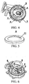
Fig 5 den schematischen Aufbau einer Zierblende eines erfindungsgemäß ausgeführten Gasherdes, -
Fig 6 schematisch die Zugehörigkeit zwischen Brennerfassung, zentralem Tropfenfänger und Zierblende beim Zusammenbau gemäß einem Ausführungsbeispiel des erfindungsgemäßen Gasherdes, -
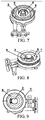
Fig 7 den schematischen Aufbau einer mit einem zentralen Tropfenfänger und einer Zierblende ausgestatteten Brennerfassung eines erfindungsgemäß ausgeführten Gasherdes, -
Fig 8 den schematischen Aufbau einer mit einer Brennerkappe, einem zentralen Tropfenfänger und einer Zierblende ausgestatteten Brennerfassung eines erfindungsgemäß ausgeführten Gasherdes, -
Fig 9 in einer weiteren Darstellung den schematischen Aufbau einer mit einer Brennerkappe, einem zentralen Tropfenfänger und einer Zierblende ausgestatteten Brennerfassung eines erfindungsgemäß ausgeführten Gasherdes und -
Fig 10 in geschnittener Darstellung eine mit einer Brennerkappe, einem zentralen Tropfenfänger und einer Zierblende ausgestattete Brennerfassung eines erfindungsgemäß ausgeführten Gasherdes. -
- 1
- Äußere Brennerkappe
- 2
- Zentrale Brennerkappe
- 3
- Äußere Kammer
- 4
- Zentrale Kammer
- 5
- Zentraler Tropfenfänger
- 6
- Zierblende
- 7
- Verbindungsteil
- 8
- Auskragung
- 9
- Erster Spalt
- 10
- Zweiter Spalt
- 11
- Luftaustrittsöffnung
- 12
- Durchgangsöffnung
- Zum besseren Verständnis der Aufgabe, Ausgestaltungen und Vorteile der vorliegenden Erfindung wird diese im Folgenden in Verbindung mit den die Erfindung beispielhaft beschreibenden bzw. nicht einschränkenden Zeichnungen und bevorzugten Ausführungsbeispielen nähert erläutert. Es sei darauf hingewiesen, dass im Rahmen der vorliegenden Erfindung mit Gasherd alle Kochgeräte bezeichnet werden, die über einen Brenner verfügen und mit beliebigen Gastypen wie beispielsweise Erdgas, Industriegas, verflüssigtem Erdölgas, Biogas und allen anderen für diesen Bereich verwendbaren Gastypen versorgt werden können.
- In
Fig 1 bis 10 ist ein Ausführungsbeispiel eines erfindungsgemäßen Gasherdes mit einer Abdeckplatte und einem Brenner dargestellt, wobei der Brenner einen Gasmischraum, eine äußere Brennerkappe 1 und eine zentrale Brennerkappe 2 umfasst. Der Gasmischraum umfasst wiederum eine äußere Kammer 3 und eine zentrale Kammer 4, wobei die äußere Brennerkappe 1 auf der äußeren Kammer 3 und die zentrale Brennerkappe 2 auf der zentralen Kammer 4 aufgesetzt ist. Darüber hinaus verfügt der Gasherd über einen zentralen Tropfenfänger 5, der sich zwischen äußerer Kammer 3 und zentraler Kammer 4 befindet und zur Sammlung und Aufnahme von zwischen äußerer Kammer 3 und zentraler Kammer 4 herunterfallenden Tropfen dient. Der zentrale Tropfenfänger 5 ist aus kaltgewalztem Blech mit einem Emaille-Überzug gefertigt. - Wie in
Fig 4 und10 gezeigt ist, sind der zentrale Tropfenfänger 5 und die äußere Kammer 3 durch einen ersten Spalt 9 voneinander getrennt, der in den Raum unterhalb der Abdeckplatte mündet und von dort dem Brenner Nebenluft zuführt. - Wie der
Abbildung 1 zu entnehmen ist, befindet sich zwischen äußerer Kammer 3 und zentraler Kammer 4 ein Verbindungsteil 7, auf dem der zentrale Tropfenfänger 5 aufgesetzt ist. Auf dem Verbindungsteil 7 sind auch noch eine Zündelektrode und ein Thermoelement aufzusetzen bzw. anzubringen. - Wie aus
Fig 2 hervorgeht, ist im zentralen Tropfenfänger 5 eine Durchgangsöffnung 12 zur Durchführung der zentralen Kammer 4, der Zündelektrode und des Thermoelements ausgebildet. Im vorliegenden Ausführungsbeispiel handelt es sich dabei um eine gemeinsame Durchgangsöffnung 12, während in der Praxis drei Durchgangsöffnungen jeweils für die zentrale Kammer 4, die Zündelektrode und das Thermoelement vorgesehen sein können. Sowohl am Außen- als auch am Innenrand, also dem der Durchgangsöffnung 12 zugewandten Rand des zentralen Tropfenfängers 5, ist eine nach oben gerichtete Anformung ausgebildet, die zusammen mit dem Grundkörper des zentralen Tropfenfängers 5 eine Aussparung zur Aufnahme von Flüssigkeiten bildet. Der zentrale Tropfenfänger 5 wird durch Stanzen hergestellt. - Wie aus
Fig 5 bis 10 ersichtlich ist, verfügt der Gasherd zusätzlich über eine kreisscheibenförmige Zierblende 6, die sich oberhalb des zentralen Tropfenfängers 5 befindet. In einer Richtung senkrecht zur Abdeckplatte deckt die Zierblende 6 den ersten Spalt 9 ab. Das heißt, in einer Draufsicht des Brenners ist der erste Spalt 9 nicht sichtbar, siehe hierzuFig 9 . In der Zierblende 6 ist in der Mitte eine kreisförmige Luftaustrittsöffnung 11 ausgebildet. Zudem ist die Zierblende 6 durch einen zweiten Spalt 10 vom zentralen Tropfenfänger 5 beabstandet, so dass die Nebenluft sukzessiv durch den ersten Spalt 9, den zweiten Spalt 10 und die Luftaustrittsöffnung 11 dem Brenner zugeführt wird. Zentrale Kammer 4, Zündelektrode und Thermoelement sind durch die Luftaustrittsöffnung 11 freigelegt. An der der zentralen Kammer 4 zugewandten Seitenwand der äußeren Kammer 3 ist eine Auskragung 8 angeformt, auf der die Zierblende 6 aufgesetzt ist. Im Konkreten erstreckt sich am Außenrand der Zierblende 6 eine umlaufende Seitenwand gleichmäßig nach unten, mit der sich die Zierblende, wie inFig 10 dargestellt, auf die Auskragung 8 stützt. Auch die Zierblende 6 ist durch Stanzen gefertigt. - Bisher wurden bevorzugte Ausführungsbeispiele der Erfindung beschrieben, aus denen sich durch Änderung bzw. Substitution einiger Merkmale weitere Ausführungsbeispiele ableiten lassen. So kann zum Beispiel an der der äußeren Kammer zugewandten Seitenwand der zentralen Kammer eine Auskragung vorgesehen sein, auf der der zentrale Tropfenfänger aufgesetzt ist. Alternativ kann sich die Auskragung, auf der der zentrale Tropfenfänger aufgesetzt ist, beispielsweise auch an der der zentralen Kammer zugewandten Seitenwand der äußeren Kammer befinden. Des Weiteren kann zwischen äußerer und zentraler Kammer ein Verbindungsteil vorhanden sein, um die Zierblende zu tragen. Überdies kann die Zierblende auch einteilig mit dem zentralen Tropfenfänger ausgeführt sein. Die Zierblende kann auch im Bereich ihrer Luftaustrittsöffnung zum zentralen Tropfenfänger geneigt ausgestaltet sein. Ferner kann die Zierblende mehrteilig, d.h. aus zwei oder mehr voneinander getrennten Bauteilen aufgebaut sein.
Claims (14)
- Gasherd mit einer Abdeckplatte und einem Brenner, der einen Gasmischraum, eine äußere Brennerkappe (1) und eine zentrale Brennerkappe (2) umfasst, wobei der Gasmischraum wiederum eine äußere Kammer (3) und eine zentrale Kammer (4) umfasst, und wobei die äußere Brennerkappe (1) auf der äußeren Kammer (3) und die zentrale Brennerkappe (2) auf der zentralen Kammer (4) aufgesetzt ist worin- zusätzlich ein zentraler Tropfenfänger (5) vorhanden ist, der sich zwischen äußerer Kammer (3) und zentraler Kammer (4) befindet und zur Sammlung und Aufnahme von zwischen äußerer Kammer (3) und zentraler Kammer (4) herunterfallenden Tropfen dient, dadurch gekennzeichnet, dass- zwischen zentralem Tropfenfänger (5) und äußerer Kammer (3) ein erster Spalt (9) ausgebildet ist, der in den Raum unterhalb der Abdeckplatte mündet und dem Brenner Nebenluft von unterhalb der Abdeckplatte zuführt.
- Gasherd gemäß Anspruch 1, dadurch gekennzeichnet, dass an der der zentralen Kammer (4) zugewandten Seitenwand der äußeren Kammer (3) eine Auskragung (8) ausgebildet ist, auf der der zentrale Tropfenfänger (5) aufgesetzt ist.
- Gasherd gemäß einem der vorhergehenden Ansprüche, dadurch gekennzeichnet, dass an der der äußeren Kammer (3) zugewandten Seitenwand der zentralen Kammer (4) eine Auskragung ausgebildet ist, auf der der zentrale Tropfenfänger (5) aufgesetzt ist.
- Gasherd gemäß einem der vorhergehenden Ansprüche, dadurch gekennzeichnet, dass sich zwischen äußerer Kammer (3) und zentraler.Kammer (4) ein Verbindungsteil (7) befindet, auf dem der zentrale Tropfenfänger (5) aufgesetzt ist.
- Gasherd gemäß einem der vorhergehenden Ansprüche, dadurch gekennzeichnet, dass im zentralen Tropfenfänger (5) eine Durchgangsöffnung (12) zur Durchführung der zentralen Kammer (4) und/oder einer Zündelektrode und/oder eines Thermoelements ausgebildet ist.
- Gasherd gemäß einem der vorhergehenden Ansprüche, dadurch gekennzeichnet, dass am Rand des zentralen Tropfenfängers (5) eine nach oben gerichtete Anformung ausgebildet ist.
- Gasherd gemäß einem der vorhergehenden Ansprüche, dadurch gekennzeichnet, dass der zentrale Tropfenfänger (5) aus kaltgewalztem Blech mit einem Emaille-Überzug gefertigt ist.
- Gasherd gemäß einem der vorhergehenden Ansprüche, dadurch gekennzeichnet, dass zusätzlich eine Zierblende (6) vorhanden ist, die sich oberhalb des zentralen Tropfenfängers (5) befindet und in einer Richtung senkrecht zur Abdeckplatte den ersten Spalt (9) abdeckt, und dass zwischen Zierblende (6) und zentralem Tropfenfänger (5) ein zweiter Spalt (10) ausgebildet ist, so dass die Nebenluft sukzessiv durch den ersten und den zweiten Spalt (9, 10) dem Brenner zugeführt wird.
- Gasherd gemäß Anspruch 8, dadurch gekennzeichnet, dass in der Zierblende (6) eine Luftaustrittsöffnung (11) ausgebildet ist, so dass die Nebenluft sukzessiv durch den ersten, den zweiten Spalt (9, 10) und die Luftaustrittsöffnung (11) dem Brenner zugeführt wird.
- Gasherd gemäß Anspruch 9, dadurch gekennzeichnet, dass die Zierblende (6) kreisscheibenförmig ausgeführt ist und sich die Luftaustrittsöffnung (11) in der Mitte der Zierblende (6) befindet.
- Gasherd gemäß einem der Ansprüche 8-10, dadurch gekennzeichnet, dass sich am Außenrand der Zierblende (6) eine umlaufende Seitenwand nach unten erstreckt.
- Gasherd gemäß einem der Ansprüche 8-11, dadurch gekennzeichnet, dass an der der zentralen Kammer (4) zugewandten Seitenwand der äußeren Kammer (3) eine Auskragung (8) ausgebildet ist, auf der die Zierblende (6) aufgesetzt ist.
- Gasherd gemäß einem der Ansprüche 8-12, dadurch gekennzeichnet, dass die Zierblende (6) und der zentrale Tropfenfänger (5) einteilig ausgeführt sind.
- Gasherd gemäß Anspruch 9, dadurch gekennzeichnet, dass die Zierblende (6) im Bereich ihrer Luftaustrittsöffnung (11) zum zentralen Tropfenfänger (5) geneigt ausgestaltet ist.
Priority Applications (1)
| Application Number | Priority Date | Filing Date | Title |
|---|---|---|---|
| PL12160550T PL2503237T3 (pl) | 2011-03-22 | 2012-03-21 | Kuchnia gazowa |
Applications Claiming Priority (1)
| Application Number | Priority Date | Filing Date | Title |
|---|---|---|---|
| CN201110075873.5A CN102692018B (zh) | 2011-03-22 | 2011-03-22 | 燃气灶 |
Publications (3)
| Publication Number | Publication Date |
|---|---|
| EP2503237A2 EP2503237A2 (de) | 2012-09-26 |
| EP2503237A3 EP2503237A3 (de) | 2015-03-25 |
| EP2503237B1 true EP2503237B1 (de) | 2016-10-05 |
Family
ID=45932157
Family Applications (1)
| Application Number | Title | Priority Date | Filing Date |
|---|---|---|---|
| EP12160550.5A Active EP2503237B1 (de) | 2011-03-22 | 2012-03-21 | Gasherd |
Country Status (4)
| Country | Link |
|---|---|
| EP (1) | EP2503237B1 (de) |
| CN (1) | CN102692018B (de) |
| ES (1) | ES2602068T3 (de) |
| PL (1) | PL2503237T3 (de) |
Families Citing this family (11)
| Publication number | Priority date | Publication date | Assignee | Title |
|---|---|---|---|---|
| CN104566445B (zh) * | 2013-10-16 | 2019-04-26 | 博西华电器(江苏)有限公司 | 燃气灶用点火针及燃气灶 |
| EP3286498B1 (de) * | 2015-04-24 | 2018-09-19 | Defendi Italy S.r.l. | Verbesserter gasbrenner mit hauptflammen mit mehreren ringen |
| ITUB20153850A1 (it) * | 2015-04-24 | 2017-03-24 | Defendi Italy Srl | Bruciatore a gas con piu corone di fiamme per piani di cottura. |
| EP3128237A1 (de) | 2015-08-03 | 2017-02-08 | Indesit Company S.p.A. | System aus gasbrennern, insbesondere für eine kochplatte für haushaltszwecke |
| CN106482109B (zh) * | 2015-09-02 | 2019-09-20 | 吴成年 | 具有保洁功能的分火器 |
| KR102395217B1 (ko) | 2015-10-14 | 2022-05-10 | 삼성전자주식회사 | 가스버너장치 및 이를 포함하는 조리기기 |
| CN106594724B (zh) * | 2016-12-23 | 2019-08-23 | 宁波方太厨具有限公司 | 一种灶具燃烧器 |
| CN106838899B (zh) * | 2017-01-22 | 2019-03-12 | 广东美的厨房电器制造有限公司 | 炉头、燃烧器和燃气灶具 |
| CN108278604A (zh) * | 2018-01-28 | 2018-07-13 | 昆山富凌能源利用有限公司 | 一种燃气灶小火盖 |
| CN110657430B (zh) * | 2018-06-30 | 2024-09-17 | 宁波方太厨具有限公司 | 一种用于灶具的燃烧器 |
| CN112283754A (zh) * | 2020-11-27 | 2021-01-29 | 迅达科技集团股份有限公司 | 一种组合式不锈钢管引射管及燃气灶具燃烧器 |
Family Cites Families (7)
| Publication number | Priority date | Publication date | Assignee | Title |
|---|---|---|---|---|
| CN2395184Y (zh) * | 1999-07-23 | 2000-09-06 | 广州市红日燃具公司 | 一种改进型家用嵌入式燃气灶具 |
| US6742514B1 (en) * | 2002-06-07 | 2004-06-01 | Eastman Outdoors | Burner assembly, outdoor stove including same, and stove kit |
| CN2658600Y (zh) * | 2003-10-31 | 2004-11-24 | 海尔集团公司 | 封闭式燃气灶 |
| CN2791485Y (zh) * | 2005-05-13 | 2006-06-28 | 台湾樱花股份有限公司 | 能使燃烧效率提升的瓦斯炉炉头 |
| CN101178177B (zh) * | 2007-04-10 | 2011-09-14 | 宁波方太厨具有限公司 | 多射流燃气燃烧器 |
| WO2009078673A2 (en) * | 2007-12-17 | 2009-06-25 | Lg Electronics Inc. | A top-burner and cooker comprising the same |
| CN201187812Y (zh) * | 2008-03-11 | 2009-01-28 | 台湾樱花股份有限公司 | 保洁型双内焰式台面炉结构 |
-
2011
- 2011-03-22 CN CN201110075873.5A patent/CN102692018B/zh not_active Expired - Fee Related
-
2012
- 2012-03-21 PL PL12160550T patent/PL2503237T3/pl unknown
- 2012-03-21 EP EP12160550.5A patent/EP2503237B1/de active Active
- 2012-03-21 ES ES12160550.5T patent/ES2602068T3/es active Active
Also Published As
| Publication number | Publication date |
|---|---|
| EP2503237A3 (de) | 2015-03-25 |
| CN102692018B (zh) | 2016-08-03 |
| ES2602068T3 (es) | 2017-02-17 |
| EP2503237A2 (de) | 2012-09-26 |
| CN102692018A (zh) | 2012-09-26 |
| PL2503237T3 (pl) | 2017-04-28 |
Similar Documents
| Publication | Publication Date | Title |
|---|---|---|
| EP2503237A2 (de) | Gasherd | |
| EP2211095A2 (de) | Gasbrenner | |
| EP3133350B1 (de) | Kombinationsgerät mit kochfeld und dunstabzugsvorrichtung mit filtereinheit | |
| EP2618054A2 (de) | Gasbrenner mit wenigstens drei Flammenkreisen | |
| EP2556304B1 (de) | Topfträger und gaskochstelle | |
| EP2505922B1 (de) | Gasherd mit zentralem Tropfenfänger | |
| EP2984410B1 (de) | Topfträgeranordnung und gaskochstelle | |
| WO2013026767A1 (de) | Gaskochfeld | |
| EP2839215A2 (de) | Brenner für ein gasbeheiztes gargerät | |
| EP3450852B1 (de) | Gaskochstelle und gasherd | |
| DE3346929A1 (de) | Brenneroberteil fuer eine gaskochstelle | |
| EP2439454A1 (de) | Gasbrenner für ein Gargerät | |
| DE2917419A1 (de) | Gas-kochmulde | |
| DE102014209955B4 (de) | Rahmenelement für ein Kochfeld | |
| EP2439449A1 (de) | Gasbrenner für ein Gargerät | |
| EP3184911A1 (de) | Höhenverstellungsvorrichtung | |
| DE102008016628A1 (de) | Gaskochfeld | |
| EP3064102A1 (de) | Kaffeeautomat | |
| DE102005026210A1 (de) | Gaskochfeld | |
| EP3046700B1 (de) | Elektrolichtbogenofen mit mehreren bodenabstichöffnungen | |
| EP1693621A1 (de) | Gaskochmulde | |
| EP1891378B1 (de) | Kochmulde | |
| DE102012204054B4 (de) | Lageranordnung | |
| DE102014005393A1 (de) | Kolonne | |
| DE10052614B4 (de) | Außenmischender Gasbrenner |
Legal Events
| Date | Code | Title | Description |
|---|---|---|---|
| PUAI | Public reference made under article 153(3) epc to a published international application that has entered the european phase |
Free format text: ORIGINAL CODE: 0009012 |
|
| AK | Designated contracting states |
Kind code of ref document: A2 Designated state(s): AL AT BE BG CH CY CZ DE DK EE ES FI FR GB GR HR HU IE IS IT LI LT LU LV MC MK MT NL NO PL PT RO RS SE SI SK SM TR |
|
| AX | Request for extension of the european patent |
Extension state: BA ME |
|
| RIC1 | Information provided on ipc code assigned before grant |
Ipc: F23D 14/06 20060101AFI20141112BHEP Ipc: F24C 15/14 20060101ALI20141112BHEP |
|
| PUAL | Search report despatched |
Free format text: ORIGINAL CODE: 0009013 |
|
| AK | Designated contracting states |
Kind code of ref document: A3 Designated state(s): AL AT BE BG CH CY CZ DE DK EE ES FI FR GB GR HR HU IE IS IT LI LT LU LV MC MK MT NL NO PL PT RO RS SE SI SK SM TR |
|
| AX | Request for extension of the european patent |
Extension state: BA ME |
|
| RAP1 | Party data changed (applicant data changed or rights of an application transferred) |
Owner name: BSH HAUSGERAETE GMBH |
|
| RIC1 | Information provided on ipc code assigned before grant |
Ipc: F23D 14/06 20060101AFI20150219BHEP Ipc: F24C 15/14 20060101ALI20150219BHEP |
|
| 17P | Request for examination filed |
Effective date: 20150925 |
|
| RBV | Designated contracting states (corrected) |
Designated state(s): AL AT BE BG CH CY CZ DE DK EE ES FI FR GB GR HR HU IE IS IT LI LT LU LV MC MK MT NL NO PL PT RO RS SE SI SK SM TR |
|
| GRAP | Despatch of communication of intention to grant a patent |
Free format text: ORIGINAL CODE: EPIDOSNIGR1 |
|
| INTG | Intention to grant announced |
Effective date: 20160519 |
|
| GRAS | Grant fee paid |
Free format text: ORIGINAL CODE: EPIDOSNIGR3 |
|
| GRAA | (expected) grant |
Free format text: ORIGINAL CODE: 0009210 |
|
| AK | Designated contracting states |
Kind code of ref document: B1 Designated state(s): AL AT BE BG CH CY CZ DE DK EE ES FI FR GB GR HR HU IE IS IT LI LT LU LV MC MK MT NL NO PL PT RO RS SE SI SK SM TR |
|
| REG | Reference to a national code |
Ref country code: GB Ref legal event code: FG4D Free format text: NOT ENGLISH |
|
| REG | Reference to a national code |
Ref country code: CH Ref legal event code: EP |
|
| REG | Reference to a national code |
Ref country code: AT Ref legal event code: REF Ref document number: 834988 Country of ref document: AT Kind code of ref document: T Effective date: 20161015 |
|
| REG | Reference to a national code |
Ref country code: IE Ref legal event code: FG4D Free format text: LANGUAGE OF EP DOCUMENT: GERMAN |
|
| REG | Reference to a national code |
Ref country code: DE Ref legal event code: R096 Ref document number: 502012008409 Country of ref document: DE |
|
| REG | Reference to a national code |
Ref country code: NL Ref legal event code: FP |
|
| REG | Reference to a national code |
Ref country code: LT Ref legal event code: MG4D |
|
| REG | Reference to a national code |
Ref country code: ES Ref legal event code: FG2A Ref document number: 2602068 Country of ref document: ES Kind code of ref document: T3 Effective date: 20170217 |
|
| PG25 | Lapsed in a contracting state [announced via postgrant information from national office to epo] |
Ref country code: LV Free format text: LAPSE BECAUSE OF FAILURE TO SUBMIT A TRANSLATION OF THE DESCRIPTION OR TO PAY THE FEE WITHIN THE PRESCRIBED TIME-LIMIT Effective date: 20161005 |
|
| REG | Reference to a national code |
Ref country code: FR Ref legal event code: PLFP Year of fee payment: 6 |
|
| PG25 | Lapsed in a contracting state [announced via postgrant information from national office to epo] |
Ref country code: NO Free format text: LAPSE BECAUSE OF FAILURE TO SUBMIT A TRANSLATION OF THE DESCRIPTION OR TO PAY THE FEE WITHIN THE PRESCRIBED TIME-LIMIT Effective date: 20170105 Ref country code: SE Free format text: LAPSE BECAUSE OF FAILURE TO SUBMIT A TRANSLATION OF THE DESCRIPTION OR TO PAY THE FEE WITHIN THE PRESCRIBED TIME-LIMIT Effective date: 20161005 Ref country code: GR Free format text: LAPSE BECAUSE OF FAILURE TO SUBMIT A TRANSLATION OF THE DESCRIPTION OR TO PAY THE FEE WITHIN THE PRESCRIBED TIME-LIMIT Effective date: 20170106 Ref country code: LT Free format text: LAPSE BECAUSE OF FAILURE TO SUBMIT A TRANSLATION OF THE DESCRIPTION OR TO PAY THE FEE WITHIN THE PRESCRIBED TIME-LIMIT Effective date: 20161005 |
|
| PG25 | Lapsed in a contracting state [announced via postgrant information from national office to epo] |
Ref country code: IS Free format text: LAPSE BECAUSE OF FAILURE TO SUBMIT A TRANSLATION OF THE DESCRIPTION OR TO PAY THE FEE WITHIN THE PRESCRIBED TIME-LIMIT Effective date: 20170205 Ref country code: HR Free format text: LAPSE BECAUSE OF FAILURE TO SUBMIT A TRANSLATION OF THE DESCRIPTION OR TO PAY THE FEE WITHIN THE PRESCRIBED TIME-LIMIT Effective date: 20161005 Ref country code: FI Free format text: LAPSE BECAUSE OF FAILURE TO SUBMIT A TRANSLATION OF THE DESCRIPTION OR TO PAY THE FEE WITHIN THE PRESCRIBED TIME-LIMIT Effective date: 20161005 Ref country code: PT Free format text: LAPSE BECAUSE OF FAILURE TO SUBMIT A TRANSLATION OF THE DESCRIPTION OR TO PAY THE FEE WITHIN THE PRESCRIBED TIME-LIMIT Effective date: 20170206 Ref country code: RS Free format text: LAPSE BECAUSE OF FAILURE TO SUBMIT A TRANSLATION OF THE DESCRIPTION OR TO PAY THE FEE WITHIN THE PRESCRIBED TIME-LIMIT Effective date: 20161005 |
|
| REG | Reference to a national code |
Ref country code: DE Ref legal event code: R097 Ref document number: 502012008409 Country of ref document: DE |
|
| PG25 | Lapsed in a contracting state [announced via postgrant information from national office to epo] |
Ref country code: DK Free format text: LAPSE BECAUSE OF FAILURE TO SUBMIT A TRANSLATION OF THE DESCRIPTION OR TO PAY THE FEE WITHIN THE PRESCRIBED TIME-LIMIT Effective date: 20161005 Ref country code: RO Free format text: LAPSE BECAUSE OF FAILURE TO SUBMIT A TRANSLATION OF THE DESCRIPTION OR TO PAY THE FEE WITHIN THE PRESCRIBED TIME-LIMIT Effective date: 20161005 Ref country code: CZ Free format text: LAPSE BECAUSE OF FAILURE TO SUBMIT A TRANSLATION OF THE DESCRIPTION OR TO PAY THE FEE WITHIN THE PRESCRIBED TIME-LIMIT Effective date: 20161005 Ref country code: SK Free format text: LAPSE BECAUSE OF FAILURE TO SUBMIT A TRANSLATION OF THE DESCRIPTION OR TO PAY THE FEE WITHIN THE PRESCRIBED TIME-LIMIT Effective date: 20161005 Ref country code: EE Free format text: LAPSE BECAUSE OF FAILURE TO SUBMIT A TRANSLATION OF THE DESCRIPTION OR TO PAY THE FEE WITHIN THE PRESCRIBED TIME-LIMIT Effective date: 20161005 |
|
| PLBE | No opposition filed within time limit |
Free format text: ORIGINAL CODE: 0009261 |
|
| STAA | Information on the status of an ep patent application or granted ep patent |
Free format text: STATUS: NO OPPOSITION FILED WITHIN TIME LIMIT |
|
| PG25 | Lapsed in a contracting state [announced via postgrant information from national office to epo] |
Ref country code: SM Free format text: LAPSE BECAUSE OF FAILURE TO SUBMIT A TRANSLATION OF THE DESCRIPTION OR TO PAY THE FEE WITHIN THE PRESCRIBED TIME-LIMIT Effective date: 20161005 Ref country code: BG Free format text: LAPSE BECAUSE OF FAILURE TO SUBMIT A TRANSLATION OF THE DESCRIPTION OR TO PAY THE FEE WITHIN THE PRESCRIBED TIME-LIMIT Effective date: 20170105 |
|
| 26N | No opposition filed |
Effective date: 20170706 |
|
| REG | Reference to a national code |
Ref country code: CH Ref legal event code: PL |
|
| PG25 | Lapsed in a contracting state [announced via postgrant information from national office to epo] |
Ref country code: SI Free format text: LAPSE BECAUSE OF FAILURE TO SUBMIT A TRANSLATION OF THE DESCRIPTION OR TO PAY THE FEE WITHIN THE PRESCRIBED TIME-LIMIT Effective date: 20161005 Ref country code: MC Free format text: LAPSE BECAUSE OF FAILURE TO SUBMIT A TRANSLATION OF THE DESCRIPTION OR TO PAY THE FEE WITHIN THE PRESCRIBED TIME-LIMIT Effective date: 20161005 |
|
| REG | Reference to a national code |
Ref country code: IE Ref legal event code: MM4A |
|
| PG25 | Lapsed in a contracting state [announced via postgrant information from national office to epo] |
Ref country code: LU Free format text: LAPSE BECAUSE OF NON-PAYMENT OF DUE FEES Effective date: 20170321 |
|
| PG25 | Lapsed in a contracting state [announced via postgrant information from national office to epo] |
Ref country code: CH Free format text: LAPSE BECAUSE OF NON-PAYMENT OF DUE FEES Effective date: 20170331 Ref country code: LI Free format text: LAPSE BECAUSE OF NON-PAYMENT OF DUE FEES Effective date: 20170331 Ref country code: IE Free format text: LAPSE BECAUSE OF NON-PAYMENT OF DUE FEES Effective date: 20170321 |
|
| REG | Reference to a national code |
Ref country code: BE Ref legal event code: MM Effective date: 20170331 |
|
| REG | Reference to a national code |
Ref country code: FR Ref legal event code: PLFP Year of fee payment: 7 |
|
| REG | Reference to a national code |
Ref country code: AT Ref legal event code: MM01 Ref document number: 834988 Country of ref document: AT Kind code of ref document: T Effective date: 20170321 |
|
| PG25 | Lapsed in a contracting state [announced via postgrant information from national office to epo] |
Ref country code: BE Free format text: LAPSE BECAUSE OF NON-PAYMENT OF DUE FEES Effective date: 20170331 |
|
| PG25 | Lapsed in a contracting state [announced via postgrant information from national office to epo] |
Ref country code: AT Free format text: LAPSE BECAUSE OF NON-PAYMENT OF DUE FEES Effective date: 20170321 |
|
| PG25 | Lapsed in a contracting state [announced via postgrant information from national office to epo] |
Ref country code: MT Free format text: LAPSE BECAUSE OF FAILURE TO SUBMIT A TRANSLATION OF THE DESCRIPTION OR TO PAY THE FEE WITHIN THE PRESCRIBED TIME-LIMIT Effective date: 20161005 |
|
| PG25 | Lapsed in a contracting state [announced via postgrant information from national office to epo] |
Ref country code: HU Free format text: LAPSE BECAUSE OF FAILURE TO SUBMIT A TRANSLATION OF THE DESCRIPTION OR TO PAY THE FEE WITHIN THE PRESCRIBED TIME-LIMIT; INVALID AB INITIO Effective date: 20120321 |
|
| PG25 | Lapsed in a contracting state [announced via postgrant information from national office to epo] |
Ref country code: CY Free format text: LAPSE BECAUSE OF NON-PAYMENT OF DUE FEES Effective date: 20161005 |
|
| PG25 | Lapsed in a contracting state [announced via postgrant information from national office to epo] |
Ref country code: MK Free format text: LAPSE BECAUSE OF FAILURE TO SUBMIT A TRANSLATION OF THE DESCRIPTION OR TO PAY THE FEE WITHIN THE PRESCRIBED TIME-LIMIT Effective date: 20161005 |
|
| PGFP | Annual fee paid to national office [announced via postgrant information from national office to epo] |
Ref country code: PL Payment date: 20200312 Year of fee payment: 9 Ref country code: NL Payment date: 20200323 Year of fee payment: 9 Ref country code: GB Payment date: 20200325 Year of fee payment: 9 |
|
| PGFP | Annual fee paid to national office [announced via postgrant information from national office to epo] |
Ref country code: FR Payment date: 20200325 Year of fee payment: 9 |
|
| PG25 | Lapsed in a contracting state [announced via postgrant information from national office to epo] |
Ref country code: AL Free format text: LAPSE BECAUSE OF FAILURE TO SUBMIT A TRANSLATION OF THE DESCRIPTION OR TO PAY THE FEE WITHIN THE PRESCRIBED TIME-LIMIT Effective date: 20161005 |
|
| PGFP | Annual fee paid to national office [announced via postgrant information from national office to epo] |
Ref country code: ES Payment date: 20200421 Year of fee payment: 9 Ref country code: DE Payment date: 20200331 Year of fee payment: 9 |
|
| REG | Reference to a national code |
Ref country code: DE Ref legal event code: R119 Ref document number: 502012008409 Country of ref document: DE |
|
| REG | Reference to a national code |
Ref country code: NL Ref legal event code: MM Effective date: 20210401 |
|
| GBPC | Gb: european patent ceased through non-payment of renewal fee |
Effective date: 20210321 |
|
| PG25 | Lapsed in a contracting state [announced via postgrant information from national office to epo] |
Ref country code: GB Free format text: LAPSE BECAUSE OF NON-PAYMENT OF DUE FEES Effective date: 20210321 Ref country code: FR Free format text: LAPSE BECAUSE OF NON-PAYMENT OF DUE FEES Effective date: 20210331 Ref country code: DE Free format text: LAPSE BECAUSE OF NON-PAYMENT OF DUE FEES Effective date: 20211001 Ref country code: NL Free format text: LAPSE BECAUSE OF NON-PAYMENT OF DUE FEES Effective date: 20210401 |
|
| REG | Reference to a national code |
Ref country code: ES Ref legal event code: FD2A Effective date: 20220523 |
|
| PG25 | Lapsed in a contracting state [announced via postgrant information from national office to epo] |
Ref country code: ES Free format text: LAPSE BECAUSE OF NON-PAYMENT OF DUE FEES Effective date: 20210322 |
|
| PG25 | Lapsed in a contracting state [announced via postgrant information from national office to epo] |
Ref country code: PL Free format text: LAPSE BECAUSE OF NON-PAYMENT OF DUE FEES Effective date: 20210321 |
|
| PGFP | Annual fee paid to national office [announced via postgrant information from national office to epo] |
Ref country code: TR Payment date: 20230316 Year of fee payment: 12 |
|
| PGFP | Annual fee paid to national office [announced via postgrant information from national office to epo] |
Ref country code: IT Payment date: 20230331 Year of fee payment: 12 |
|
| PG25 | Lapsed in a contracting state [announced via postgrant information from national office to epo] |
Ref country code: IT Free format text: LAPSE BECAUSE OF NON-PAYMENT OF DUE FEES Effective date: 20240321 |