EP2503247A2 - Four de chauffage - Google Patents
Four de chauffage Download PDFInfo
- Publication number
- EP2503247A2 EP2503247A2 EP12152383A EP12152383A EP2503247A2 EP 2503247 A2 EP2503247 A2 EP 2503247A2 EP 12152383 A EP12152383 A EP 12152383A EP 12152383 A EP12152383 A EP 12152383A EP 2503247 A2 EP2503247 A2 EP 2503247A2
- Authority
- EP
- European Patent Office
- Prior art keywords
- valve
- stove
- valve closure
- stove according
- rotary control
- Prior art date
- Legal status (The legal status is an assumption and is not a legal conclusion. Google has not performed a legal analysis and makes no representation as to the accuracy of the status listed.)
- Granted
Links
- 210000003195 fascia Anatomy 0.000 claims abstract description 14
- 238000002485 combustion reaction Methods 0.000 claims abstract description 12
- 230000001105 regulatory effect Effects 0.000 claims abstract description 3
- 230000015572 biosynthetic process Effects 0.000 claims description 13
- 230000000295 complement effect Effects 0.000 claims description 6
- 230000000452 restraining effect Effects 0.000 claims description 2
- 230000001419 dependent effect Effects 0.000 claims 1
- 239000004449 solid propellant Substances 0.000 description 3
- 230000000694 effects Effects 0.000 description 2
- 239000000446 fuel Substances 0.000 description 2
- 239000000779 smoke Substances 0.000 description 2
- 230000006835 compression Effects 0.000 description 1
- 238000007906 compression Methods 0.000 description 1
- 238000010276 construction Methods 0.000 description 1
- 230000000994 depressogenic effect Effects 0.000 description 1
- 238000010438 heat treatment Methods 0.000 description 1
- 239000003779 heat-resistant material Substances 0.000 description 1
- 239000007769 metal material Substances 0.000 description 1
- 230000000717 retained effect Effects 0.000 description 1
- 230000009291 secondary effect Effects 0.000 description 1
- 239000005341 toughened glass Substances 0.000 description 1
- 230000000007 visual effect Effects 0.000 description 1
Images


Classifications
-
- F—MECHANICAL ENGINEERING; LIGHTING; HEATING; WEAPONS; BLASTING
- F24—HEATING; RANGES; VENTILATING
- F24B—DOMESTIC STOVES OR RANGES FOR SOLID FUELS; IMPLEMENTS FOR USE IN CONNECTION WITH STOVES OR RANGES
- F24B13/00—Details solely applicable to stoves or ranges burning solid fuels
- F24B13/002—Surrounds
-
- F—MECHANICAL ENGINEERING; LIGHTING; HEATING; WEAPONS; BLASTING
- F24—HEATING; RANGES; VENTILATING
- F24B—DOMESTIC STOVES OR RANGES FOR SOLID FUELS; IMPLEMENTS FOR USE IN CONNECTION WITH STOVES OR RANGES
- F24B5/00—Combustion-air or flue-gas circulation in or around stoves or ranges
- F24B5/02—Combustion-air or flue-gas circulation in or around stoves or ranges in or around stoves
- F24B5/021—Combustion-air or flue-gas circulation in or around stoves or ranges in or around stoves combustion-air circulation
- F24B5/026—Supply of primary and secondary air for combustion
-
- F—MECHANICAL ENGINEERING; LIGHTING; HEATING; WEAPONS; BLASTING
- F24—HEATING; RANGES; VENTILATING
- F24B—DOMESTIC STOVES OR RANGES FOR SOLID FUELS; IMPLEMENTS FOR USE IN CONNECTION WITH STOVES OR RANGES
- F24B5/00—Combustion-air or flue-gas circulation in or around stoves or ranges
- F24B5/02—Combustion-air or flue-gas circulation in or around stoves or ranges in or around stoves
- F24B5/021—Combustion-air or flue-gas circulation in or around stoves or ranges in or around stoves combustion-air circulation
- F24B5/023—Supply of primary air for combustion
-
- F—MECHANICAL ENGINEERING; LIGHTING; HEATING; WEAPONS; BLASTING
- F23—COMBUSTION APPARATUS; COMBUSTION PROCESSES
- F23L—SUPPLYING AIR OR NON-COMBUSTIBLE LIQUIDS OR GASES TO COMBUSTION APPARATUS IN GENERAL ; VALVES OR DAMPERS SPECIALLY ADAPTED FOR CONTROLLING AIR SUPPLY OR DRAUGHT IN COMBUSTION APPARATUS; INDUCING DRAUGHT IN COMBUSTION APPARATUS; TOPS FOR CHIMNEYS OR VENTILATING SHAFTS; TERMINALS FOR FLUES
- F23L13/00—Construction of valves or dampers for controlling air supply or draught
- F23L13/02—Construction of valves or dampers for controlling air supply or draught pivoted about a single axis but having not other movement
-
- F—MECHANICAL ENGINEERING; LIGHTING; HEATING; WEAPONS; BLASTING
- F24—HEATING; RANGES; VENTILATING
- F24B—DOMESTIC STOVES OR RANGES FOR SOLID FUELS; IMPLEMENTS FOR USE IN CONNECTION WITH STOVES OR RANGES
- F24B1/00—Stoves or ranges
- F24B1/02—Closed stoves
- F24B1/028—Closed stoves with means for regulating combustion
Definitions
- the present invention relates to a stove, and in particular to an inset stove for burning solid fuel such as logs.
- inset stove As it is received in an opening in a wall so that its front fascia lies flush with or protrudes only by a small distance from the surface of the wall in which the inset stove is received.
- Stoves of this type include a combustion chamber or firebox in which fuel such as logs is received.
- a door provides access to the firebox, which has a flue outlet through which smoke and other combustion products are exhausted to the outside of the stove, typically through a flue provided in the building in which the stove is installed.
- the stove is provided with vents or air inlets through which external air can be introduced into the firebox to control the rate of combustion of the fuel.
- vents are provided towards a front surface of the stove and have a slotted grill, behind which a damper plate is slideably mounted.
- a lever is attached to the damper plate to allow the damper plate to be moved to cover or partially cover the slots in the grill, thereby preventing or restricting airflow through the slots of the grill into the firebox.
- Vents of this type can be difficult to operate accurately, because of the difficulty in manually moving the damper plate to a precise position in which a desired airflow is achieved. Moreover, as it can be difficult to achieve repeatedly a particular airflow setting because of the difficulty in manually moving the damper to exactly the same position as it has previously occupied, repeatability is a problem in stoves with vents of this type. Additionally, the lever which controls the damper plate typically projects outwardly of a front fascia of the stove, which can be unsightly and can therefore have a negative aesthetic effect on the stove, particular where the stove is an inset stove which is designed to have a substantially flat fascia.
- a stove comprising a combustion chamber and a valve assembly for regulating air flow into the combustion chamber, wherein the valve assembly comprises a valve aperture, a valve gasket for closing the valve aperture and rotary control means for raising the valve closure towards the valve aperture and lowering the valve closure away from the valve aperture, wherein the rotary control means is positioned so as to be recessed with respect to a fascia of the stove, the stove further comprising concealing means for concealing the rotary control means.
- rotary control means in the stove of the first aspect of the invention permits greater precision and repeatability in positioning the valve gasket than in prior art stoves, as the rotary control means can easily be set to a previously used setting in which the valve gasket is positioned to achieve a desired airflow, whilst the recessed position of the rotary control means with respect to the fascia, and the concealing means allow the rotary control means to be concealed to add to the aesthetic appeal of the stove.
- a door of the stove may be provided with a cut-out section for accommodating the rotary control means.
- the stove may further comprise latching means for securing the door in its closed position.
- the latching means may comprise a rod which is rotatably mounted in part of the door and which has an engagement formation that is configured to engage with a complementary receiving formation provided in part of the stove which is positioned adjacent the rod when the door is closed.
- the latching means may further comprise a lever which is attached to the rod and can be moved to cause rotation of the rod.
- the concealing means may comprise a panel provided on the lever, which panel is configured to be received in the cut-out section of the door.
- the panel may be provided with latching means for holding the panel in position and restraining movement of the lever.
- the valve assembly may comprise a mechanical linkage which links the rotary control means to the valve.
- the mechanical linkage may comprise a control screw which is fixed to the rotary control means for rotary motion therewith, the control screw having a free end which abuts against a free end of a push rod, the push rod having a free distal end which engages with a first arm of a pivotally mounted bell crank having a second arm which acts on the valve such that rotation of the rotary control means causes pivotal motion of the bell crank and hence movement of the valve.
- the valve may be provided with aligned notches in front portions of side plates of the valve by means of which the valve is mounted on a valve shaft such that movement of the bell crank causes pivotal movement of the valve around the valve shaft.
- the valve may be provided with a weight which is positioned intermediate the notches and a rear portion of the valve.
- a rod may be mounted on a distal end of the second arm of the bell crank for engagement with an underside of a top plate of the valve such that if pivotal motion of the valve around the valve shaft is impeded by contact between the rear portion of the valve and an object, further movement of the bell crank causes the valve to pivot about a point of contact between the rear portion of the valve and the object.
- the valve may be provided with a valve gasket.
- the valve assembly may comprise stop means for limiting the extent of rotation of the rotary control means.
- the stop means may comprise a first pin which projects from a portion of the valve assembly for engagement with a second pin which is associated with the rotary control means.
- the valve assembly may be provided with a resilient tongue for biasing the valve assembly towards a position in which the valve is correctly positioned with respect to valve apertures of the stove.
- the valve assembly may be provided as a removable cartridge.
- valve assembly for a stove, the valve assembly comprising a valve for closing a valve aperture of the stove and rotary control means for raising the valve closure towards the valve aperture and lowering the valve closure away from the valve aperture.
- valve assembly of the second aspect of the invention permits greater precision and repeatability in positioning the valve gasket than in prior art stoves, as the rotary control means can easily be set to a previously used setting in which the valve gasket is positioned to achieve a desired airflow into a combustion chamber of a stove in which the valve assembly is installed.
- valve assembly may further comprise any of the features recited above in relation to the valve assembly of the stove of the first aspect of the invention.
- a stove is shown generally at 10.
- the stove shown in Figure 1 is an inset stove which is intended to be received in an opening in a wall of a building such as a domestic dwelling.
- the stove 10 has a frame 12, a rear side of which abuts the wall around the opening when the stove 10 is installed, such that a front face of the frame 12 faces away from the wall.
- the frame 12 is attached to a stove body 14 which extends rearwardly of the frame 12 and, when the stove 10 is installed, is received in the opening in the wall.
- a door 16 is attached to the stove body 14 by means of a hinge 18, and opens to permit access to an interior of the stove 10.
- the door 16 in this example takes the form of a frame 20 of a metallic material that surrounds a panel 22 of tempered glass or another heat resistant material to permit visual access to the interior of the stove 10.
- the frame 20 of the door 16 is provided with a cut-out section 24 to accommodate rotary control knobs 26 of a valve assembly of the stove 10, which are positioned so as to be recessed with respect to a fascia of the stove 10 (which in this example is provided by the door 16) so that when the they can be concealed to provide a substantially flat fascia to add to the aesthetic appeal of the stove 10.
- the door 16 includes latching means to secure it in its closed position.
- the latching means 30 in this example comprises a rod 32 which is rotatably mounted at the opposite side of the door 16 to the hinge 18.
- the rod 32 includes a latch formation in the form of a hook 34 which extends outwardly of the rod and is configured to engage with a complementary receiving formation in a part of the stove 10 such as the frame 12 or body 14 of the stove 10 that is positioned adjacent the rod 32 when the door 16 is closed, to latch the door 16 in its closed position.
- a lower end of the rod 32 is received in a sleeve from which a lever 36 extends, in a direction generally opposed to the direction of the latch formation 34.
- the lever 36 When the door 16 is closed, the lever 36 extends laterally of the rod 32 beneath the frame 20 of the door, such that the lever does not protrude outwardly beyond the pane of the frame 20 of the door 16..
- the lever 36 terminates in a panel 38 which, when the door 16 is closed, is received in the cut-out section 24 of the frame 20 and lies substantially flush with the frame 20 of the door 16 to conceal the rotary control knobs 26 of the stove 10.
- a rear side of the panel 38 is provided with a tab which can be received by a spring latch provided in this example at a position intermediate the rotary control knobs 26, but which may be provided on the frame 20 of the door 16 or in any appropriate position on the stove body 14, to hold the panel 38 in position and thus prevent movement of the lever 32 and opening of the door 16.
- FIG 3 shows the stove 10 with the door 16 closed, from which it can be seen that when the door is closed the panel 38 conceals the rotary control knobs 26. In this way, with the door 16 closed the stove 10 has a substantially flat fascia..
- the panel 38 is depressed to release the spring latch, permitting movement of the panel 38 and lever 36.
- the lever 36 is then pivoted outwardly of the frame 12 of the stove 10.
- the lever 36 is free to rotate through a predefined angle without causing the rod 32 to rotate, to permit access to the rotary control knobs 26 without releasing the latch formation 34 from its engagement with the complementary receiving formation.
- the angle is approximately 60 degrees, as this causes the lever 36 and the panel 38 to move sufficiently far from frame 12 of the stove to allows adequate room for the rotary control knobs 26 to be accessed. It will be appreciated that any angle of rotation that achieves this could equally be employed.
- the sleeve engages with the rod 32, causing the rod 32 to rotate, which in turns causes the latch formation 34 to disengage from the complementary receiving formation. Once the latch formation 34 has completely disengaged from the receiving formation the door 16 can be opened to permit access to the interior of the stove 10.
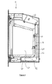
- FIG 4 is a schematic cross-sectional view taken from one side of the stove 10.
- the stove 10 includes a combustion chamber or firebox 40, which is positioned so as to be visible though the panel 22 of the door 16 when the door 16 is closed.
- a flue outlet 42 is provided in an upper part of the firebox 40 to allow smoke and other combustion products to be exhausted to an exterior of the stove 10, typically through a flue provided in the building in which the stove is installed.
- a rear wall 44 of the firebox 40 is provided, towards an upper part, with a first air inlet 46, and towards a lower part with a second air inlet 48.
- the first air inlet 46 communicates with a first conduit 50 which receives air from an exterior of the stove 10, whilst the second air inlet 48 communicates with a second conduit 52 which receives air from the exterior of the stove 10.
- the first conduit 50 contains a first valve which is controlled by one of the rotary control knobs 26, and the second conduit 52 contains a second valve which is controlled by the other of the rotary control knobs 26, as is described in detail below.
- the stove 10 includes a valve assembly 60 which controls airflow to the first and second air inlets 46, 48 of the firebox 40.
- the valve assembly is provided as a removable cartridge 62 which slots into the stove body 14 beneath the firebox 40, as shown in Figure 4 . This arrangement is advantageous as it facilitates servicing or replacement of the valve assembly 60, as the cartridge 62 can simply be slid out of the stove body 14 without disassembling the stove 10.
- FIG. 5 is a schematic perspective representation of the valve assembly 60.
- the valve assembly includes a control fascia 64 on which the rotary control knobs 26 are mounted.
- the control fascia 64 is connected to a valve frame 66 in which first and second valve closures 68, 70 are received.
- the first and second valve closures 68, 70 each have a valve gasket 72 which securely seals an aperture in the first or second conduit 50, 52 when the valve closures 68, 70 are raised to a position in which they are fully engaged with the aperture, to close the aperture and prevent air flow to the first and second air inlets 46, 48.
- FIG. 6 The exploded perspective view of Figure 6 shows the arrangement linking one of the rotary control knobs 26 to the first valve closure 68, but it is to be appreciated that the arrangement linking the other control knob 26 to the second valve closure 70 is identical in its construction and operation, but is a mirror image of the arrangement shown in Figure 6 , as can be seen from Figure 5 .
- the rotary control knob 26 is mounted on a threaded control screw 74 which passes through an aperture in the control fascia 64 and a co-axial threaded aperture in a thread block 76 which is disposed immediately behind the control fascia 64.
- the control knob 26 is secured to the control screw 74 by means of a grub screw 78.
- a compression spring 80 is mounted on the control screw 74 and abuts at one end against a washer 82 which is retained by a pin 83 which passes through the control screw 74 and at the other end against the thread block 76 to bias the control screw 74 towards an extended position.
- the thread of the aperture in the thread block 76 is complementary to the thread of the control screw 74 such that when the control screw 74 is rotated by anti-clockwise rotation of the control knob 26 a free distal end 84 of the control screw 74 extends linearly away from the thread block 76, and when the control screw 74 is rotated in a clockwise direction the free distal end 84 of the control screw 74 retracts linearly towards the thread block 76.
- the inter-engagement of the threads of the control screw 74 and the aperture of the thread block 76 also acts to hold the control screw 74, and thus the control knob 26, in position when rotation of the control knob 26 ceases.
- the valve frame 66 has two side plates 94 which are substantially parallel to each other and which have attachment lugs 96 that are substantially perpendicular to the side plates 92 such that when the side plates 94 are attached to the front plate 92 by means of the attachment lugs 96 the side plates 94 are substantially perpendicular to the front plate 94.
- the valve frame 66 also has a floor plate 97 which extends between the side plates 94.
- a tongue 98 extends outwardly of a rear edge of the floor plate 97.
- the tongue 98 is resiliently biased in a downward direction and, when the valve assembly 60 is received in the stove 10, engages with a base plate of the stove to urge the top of the valve frame 66 towards a plate in which air inlets of the conduits 50, 52 are provided, to hold the valve frame 66 securely in the correct position with respect to the air inlets of the conduits 50, 52.
- the tongue 98 also has a secondary effect of impeding movement of the valve assembly 60 with respect to the stove 10, but does not prevent removal of the valve assembly 60 from the stove if sufficient force is applied to pull the valve assembly 60 out of the stove 10.
- a first pair of mounting holes 100 are provided in a forward portion of each of the side plates 94 for receiving a substantially cylindrical bell crank shaft 102.
- the first mounting holes 100 of the side plates 94 are aligned, such that when the bell crank shaft 102 is received in the first mounting holes 100 its longitudinal axis is substantially parallel to the front plate 92 of the valve frame 66.
- a second pair of mounting holes 104 are provided in a rear portion of each of the side plates for receiving a substantially cylindrical valve shaft 106. The second holes are aligned such that when the valve shaft 106 is received in the second holes 106 its longitudinal axis is substantially parallel to the front plate 92 and the longitudinal axis of the bell crank shaft 102.
- a bell crank 108 is attached to an exterior surface of one end of hollow, generally cylindrical sleeve 110 which is rotatably mounted on the bell crank shaft 102, such that when the bell crank shaft 102 and the sleeve 110 are installed in the valve frame 60 the bell crank 108 is positioned adjacent one of the side plates 94 and can rotate about the bell crank shaft 102.
- the bell crank 108 has a generally flat first arm 111 which acts as an engagement portion.
- a hole or recess is provided in the first arm 111 to retain a distal end of the push rod 88.
- One side of a free end of the first arm 111 is attached to the exterior surface of the end of the sleeve 110.
- a second arm 112 extends outwardly of the first arm 111 in a direction generally perpendicular to the first arm 111, such that in normal use of the valve assembly 60 the second arm 112 extends towards a rear of the valve assembly 60.
- a distal end portion 114 of the second arm 112 is angled upwardly with respect to the second arm 112, and a generally cylindrical rod 116 is mounted on the distal end portion 114 of the second arm 112 extending in a direction generally perpendicular to the second arm 112 such that a longitudinal axis of the rod 116 is substantially parallel to those of the bell crank shaft 102 and the valve shaft 106.
- the first valve closure 68 has first and second side plates 118 which are disposed in a substantially parallel spaced configuration, being linked together by a top plate 120.
- the first and second side plates 118 are each provided with a notch 122 in a front portion of the first and second side plates 118, and when the first valve closure 68 is assembled these notches 122 are aligned such that the first valve closure 68 can be rotatably mounted on the valve shaft 106 by receiving the valve shaft 106 in the aligned notches 122.
- a valve weight 124 is attached to an underside of the top plate 120 at a position intermediate the notches 122 and a rear edge 126 of the top plate 120, and the valve gasket 72 is provided on an upper surface of the top plate 120.
- the first valve closure 68 When the valve assembly 60 is assembled, the first valve closure 68 is mounted on the valve shaft 106, and the valve weight 124 causes the valve closure 68 to rotate in a clockwise direction until the underside of the top plate 120 abuts against the rod 116. Thus, in normal operation of the valve assembly the first valve closure 68 is supported by the valve shaft 106 and by the rod 116.
- valve assembly 60 is cross-sectional views of the valve assembly 60 with the valves in different positions corresponding to different airflow settings.
- Figure 7 shows the valve assembly 60 with the first valve closure 68 in a fully open position. In this position the valve closure 68 rests on a stop 130 of the valve assembly 60.
- Rotation of the control knob 26 in an anti-clockwise direction causes the control screw 74 to move towards the valve closure 68, which in turn causes the push rod 88 to extend.
- the distal end of the push rod 88 which abuts against the first arm 111 of the bell crank 108, causes the bell crank 108 to rotate about the bell crank shaft 102.
- the second arm 112 of the bell crank 108 therefore rotates in an anti-clockwise direction, as shown by the arrow 132 of Figure 8 , and the magnitude of the rotation of the second arm 112 is much larger than the magnitude of the movement of the push rod 88, i.e. the bell crank 108 amplifies the motion of the push rod 88.
- the rod 116 mounted on the distal end portion of the second arm 112 moves with the second arm 112, and as the underside of the top plate 120 of the valve closure 68 abuts against the rod 116, this causes the valve closure 68 to be raised by pivoting around the valve shaft 106.
- the position of the valve weight 124 intermediate the notches 122 and the rear edge 126 of the top plate 120 ensures that the rear edge 126 of the top plate 120 is lifted before the front edge of the top plate 120. This has advantageous effects, which are described below.
- the rotation of the control knob is limited by a first pin 136 which passes through the control screw 74 and interacts with a second pin 138 which extends rearwardly of the thread block 76.
- the first pin 13 acts as a stop to limit rotation of the control screw 74 in either direction.
- the length and position of the first and second pins 136, 138 are selected so that the degree of rotation permitted by the interacting first and second pins 136, 138 ensures that the valve closure 68 has sufficient travel to become fully seated (closed) and fully open with sufficient tolerance to accommodate slight variations in stove dimensions.
Landscapes
- Engineering & Computer Science (AREA)
- Chemical & Material Sciences (AREA)
- Combustion & Propulsion (AREA)
- Mechanical Engineering (AREA)
- General Engineering & Computer Science (AREA)
- Feeding And Controlling Fuel (AREA)
- Cookers (AREA)
- Solid-Fuel Combustion (AREA)
- Mechanically-Actuated Valves (AREA)
Applications Claiming Priority (1)
| Application Number | Priority Date | Filing Date | Title |
|---|---|---|---|
| GB1104740.4A GB2489240B (en) | 2011-03-22 | 2011-03-22 | A stove |
Publications (3)
| Publication Number | Publication Date |
|---|---|
| EP2503247A2 true EP2503247A2 (fr) | 2012-09-26 |
| EP2503247A3 EP2503247A3 (fr) | 2015-08-12 |
| EP2503247B1 EP2503247B1 (fr) | 2017-10-25 |
Family
ID=44012910
Family Applications (1)
| Application Number | Title | Priority Date | Filing Date |
|---|---|---|---|
| EP12152383.1A Not-in-force EP2503247B1 (fr) | 2011-03-22 | 2012-01-25 | Four de chauffage |
Country Status (5)
| Country | Link |
|---|---|
| EP (1) | EP2503247B1 (fr) |
| DK (1) | DK2503247T3 (fr) |
| ES (1) | ES2654591T3 (fr) |
| GB (1) | GB2489240B (fr) |
| PT (1) | PT2503247T (fr) |
Family Cites Families (8)
| Publication number | Priority date | Publication date | Assignee | Title |
|---|---|---|---|---|
| US4313418A (en) * | 1980-03-18 | 1982-02-02 | Janice E. Schrader | Damper control |
| US4483312A (en) * | 1980-07-01 | 1984-11-20 | Martenson Donald S | Free standing stove |
| US4475529A (en) * | 1981-04-29 | 1984-10-09 | Milligan Orley J | Solid fuel burning stove with exterior rear wall baffle |
| GB2389414B (en) * | 2002-06-06 | 2005-09-28 | A J Wells & Sons | Stove |
| DE10248288A1 (de) * | 2002-10-16 | 2004-05-06 | Cera-Design By Britta Von Tasch Gmbh | Mehrseitig einsehbare Feuerstätte |
| US20050194002A1 (en) * | 2004-03-05 | 2005-09-08 | Henry Daniel S. | Adjustable air bypass system for heating appliance |
| DE202008004505U1 (de) * | 2008-04-01 | 2008-07-31 | Leda-Werk Gmbh & Co. Kg Boekhoff & Co. | Kaminofen zum Verbrennen von Feststoffen mit zumindest einem Verbrennungsraum |
| US8469021B2 (en) * | 2009-03-19 | 2013-06-25 | Travis Industries, Inc. | Fireplace assembly with integrated burn control system |
-
2011
- 2011-03-22 GB GB1104740.4A patent/GB2489240B/en not_active Expired - Fee Related
-
2012
- 2012-01-25 ES ES12152383.1T patent/ES2654591T3/es active Active
- 2012-01-25 DK DK12152383.1T patent/DK2503247T3/en active
- 2012-01-25 EP EP12152383.1A patent/EP2503247B1/fr not_active Not-in-force
- 2012-01-25 PT PT121523831T patent/PT2503247T/pt unknown
Non-Patent Citations (1)
| Title |
|---|
| None |
Also Published As
| Publication number | Publication date |
|---|---|
| EP2503247B1 (fr) | 2017-10-25 |
| ES2654591T3 (es) | 2018-02-14 |
| GB201104740D0 (en) | 2011-05-04 |
| EP2503247A3 (fr) | 2015-08-12 |
| PT2503247T (pt) | 2018-01-04 |
| DK2503247T3 (en) | 2018-01-08 |
| GB2489240B (en) | 2016-06-15 |
| GB2489240A (en) | 2012-09-26 |
Similar Documents
| Publication | Publication Date | Title |
|---|---|---|
| US5025776A (en) | Door mounted hinge for oven doors and the like | |
| CN113100639B (zh) | 烹饪设备 | |
| US4001973A (en) | Removable door hinge system | |
| US6257230B1 (en) | Adapter for ventless fireplace | |
| EP2503247A2 (fr) | Four de chauffage | |
| US3067736A (en) | Hinge mechanism | |
| US4512330A (en) | Fireplace screen | |
| CA2760851A1 (fr) | Charniere de porte pour ouvrir et fermer la porte d'un appareil electromenager | |
| KR20120041388A (ko) | 상하 개폐식 가구 도어용 경첩 | |
| US5829426A (en) | Apparatus for holding the lid of barbeque grill | |
| JP4758224B2 (ja) | 開口部装置 | |
| US5027787A (en) | Single cavity gas oven and grill unit | |
| US2216101A (en) | Damper control | |
| US3498285A (en) | Stove latch | |
| US1161523A (en) | Automatic cooking apparatus. | |
| KR101943765B1 (ko) | 좌우 겸용 도어 로킹장치 | |
| US2845923A (en) | Oven door hinge mechanism | |
| PL216103B1 (pl) | Sposób sterowania zintegrowanym mechanizmem klapy szybra i zamka drzwi paleniska kominkowego oraz zintegrowany mechanizm klapy szybra i zamka drzwi paleniska kominkowego | |
| AU2011201318B2 (en) | Improvements to Solid Fuel Burners | |
| KR200245303Y1 (ko) | 가스자동차단장치 | |
| CN201116415Y (zh) | 电磁锁的启闭状态调整结构 | |
| JP2012202044A (ja) | 誤ロック防止装置及びそれを備えた窓用ロック装置 | |
| US1951698A (en) | Oven door | |
| CN208710895U (zh) | 一种消防栓箱门专用开合结构 | |
| RU176002U1 (ru) | Устройство для управления заслонкой горелки биокамина |
Legal Events
| Date | Code | Title | Description |
|---|---|---|---|
| PUAI | Public reference made under article 153(3) epc to a published international application that has entered the european phase |
Free format text: ORIGINAL CODE: 0009012 |
|
| AK | Designated contracting states |
Kind code of ref document: A2 Designated state(s): AL AT BE BG CH CY CZ DE DK EE ES FI FR GB GR HR HU IE IS IT LI LT LU LV MC MK MT NL NO PL PT RO RS SE SI SK SM TR |
|
| AX | Request for extension of the european patent |
Extension state: BA ME |
|
| PUAL | Search report despatched |
Free format text: ORIGINAL CODE: 0009013 |
|
| AK | Designated contracting states |
Kind code of ref document: A3 Designated state(s): AL AT BE BG CH CY CZ DE DK EE ES FI FR GB GR HR HU IE IS IT LI LT LU LV MC MK MT NL NO PL PT RO RS SE SI SK SM TR |
|
| AX | Request for extension of the european patent |
Extension state: BA ME |
|
| RIC1 | Information provided on ipc code assigned before grant |
Ipc: F24B 5/02 20060101AFI20150706BHEP Ipc: F24B 13/00 20060101ALI20150706BHEP Ipc: F23L 13/02 20060101ALI20150706BHEP |
|
| 17P | Request for examination filed |
Effective date: 20160210 |
|
| RBV | Designated contracting states (corrected) |
Designated state(s): AL AT BE BG CH CY CZ DE DK EE ES FI FR GB GR HR HU IE IS IT LI LT LU LV MC MK MT NL NO PL PT RO RS SE SI SK SM TR |
|
| 17Q | First examination report despatched |
Effective date: 20160603 |
|
| GRAP | Despatch of communication of intention to grant a patent |
Free format text: ORIGINAL CODE: EPIDOSNIGR1 |
|
| INTG | Intention to grant announced |
Effective date: 20170606 |
|
| GRAS | Grant fee paid |
Free format text: ORIGINAL CODE: EPIDOSNIGR3 |
|
| GRAA | (expected) grant |
Free format text: ORIGINAL CODE: 0009210 |
|
| AK | Designated contracting states |
Kind code of ref document: B1 Designated state(s): AL AT BE BG CH CY CZ DE DK EE ES FI FR GB GR HR HU IE IS IT LI LT LU LV MC MK MT NL NO PL PT RO RS SE SI SK SM TR |
|
| REG | Reference to a national code |
Ref country code: GB Ref legal event code: FG4D |
|
| REG | Reference to a national code |
Ref country code: CH Ref legal event code: EP |
|
| REG | Reference to a national code |
Ref country code: AT Ref legal event code: REF Ref document number: 940288 Country of ref document: AT Kind code of ref document: T Effective date: 20171115 |
|
| REG | Reference to a national code |
Ref country code: IE Ref legal event code: FG4D |
|
| REG | Reference to a national code |
Ref country code: DE Ref legal event code: R096 Ref document number: 602012038835 Country of ref document: DE |
|
| REG | Reference to a national code |
Ref country code: PT Ref legal event code: SC4A Ref document number: 2503247 Country of ref document: PT Date of ref document: 20180104 Kind code of ref document: T Free format text: AVAILABILITY OF NATIONAL TRANSLATION Effective date: 20171227 |
|
| REG | Reference to a national code |
Ref country code: DK Ref legal event code: T3 Effective date: 20180105 |
|
| REG | Reference to a national code |
Ref country code: NL Ref legal event code: FP |
|
| REG | Reference to a national code |
Ref country code: FR Ref legal event code: PLFP Year of fee payment: 7 |
|
| REG | Reference to a national code |
Ref country code: SE Ref legal event code: TRGR |
|
| REG | Reference to a national code |
Ref country code: ES Ref legal event code: FG2A Ref document number: 2654591 Country of ref document: ES Kind code of ref document: T3 Effective date: 20180214 |
|
| REG | Reference to a national code |
Ref country code: LT Ref legal event code: MG4D |
|
| REG | Reference to a national code |
Ref country code: AT Ref legal event code: MK05 Ref document number: 940288 Country of ref document: AT Kind code of ref document: T Effective date: 20171025 |
|
| PGFP | Annual fee paid to national office [announced via postgrant information from national office to epo] |
Ref country code: NL Payment date: 20180119 Year of fee payment: 7 |
|
| PG25 | Lapsed in a contracting state [announced via postgrant information from national office to epo] |
Ref country code: LT Free format text: LAPSE BECAUSE OF FAILURE TO SUBMIT A TRANSLATION OF THE DESCRIPTION OR TO PAY THE FEE WITHIN THE PRESCRIBED TIME-LIMIT Effective date: 20171025 Ref country code: NO Free format text: LAPSE BECAUSE OF FAILURE TO SUBMIT A TRANSLATION OF THE DESCRIPTION OR TO PAY THE FEE WITHIN THE PRESCRIBED TIME-LIMIT Effective date: 20180125 Ref country code: FI Free format text: LAPSE BECAUSE OF FAILURE TO SUBMIT A TRANSLATION OF THE DESCRIPTION OR TO PAY THE FEE WITHIN THE PRESCRIBED TIME-LIMIT Effective date: 20171025 |
|
| PGFP | Annual fee paid to national office [announced via postgrant information from national office to epo] |
Ref country code: DE Payment date: 20180122 Year of fee payment: 7 Ref country code: DK Payment date: 20180119 Year of fee payment: 7 Ref country code: ES Payment date: 20180227 Year of fee payment: 7 |
|
| PG25 | Lapsed in a contracting state [announced via postgrant information from national office to epo] |
Ref country code: IS Free format text: LAPSE BECAUSE OF FAILURE TO SUBMIT A TRANSLATION OF THE DESCRIPTION OR TO PAY THE FEE WITHIN THE PRESCRIBED TIME-LIMIT Effective date: 20180225 Ref country code: GR Free format text: LAPSE BECAUSE OF FAILURE TO SUBMIT A TRANSLATION OF THE DESCRIPTION OR TO PAY THE FEE WITHIN THE PRESCRIBED TIME-LIMIT Effective date: 20180126 Ref country code: HR Free format text: LAPSE BECAUSE OF FAILURE TO SUBMIT A TRANSLATION OF THE DESCRIPTION OR TO PAY THE FEE WITHIN THE PRESCRIBED TIME-LIMIT Effective date: 20171025 Ref country code: BG Free format text: LAPSE BECAUSE OF FAILURE TO SUBMIT A TRANSLATION OF THE DESCRIPTION OR TO PAY THE FEE WITHIN THE PRESCRIBED TIME-LIMIT Effective date: 20180125 Ref country code: AT Free format text: LAPSE BECAUSE OF FAILURE TO SUBMIT A TRANSLATION OF THE DESCRIPTION OR TO PAY THE FEE WITHIN THE PRESCRIBED TIME-LIMIT Effective date: 20171025 Ref country code: LV Free format text: LAPSE BECAUSE OF FAILURE TO SUBMIT A TRANSLATION OF THE DESCRIPTION OR TO PAY THE FEE WITHIN THE PRESCRIBED TIME-LIMIT Effective date: 20171025 Ref country code: RS Free format text: LAPSE BECAUSE OF FAILURE TO SUBMIT A TRANSLATION OF THE DESCRIPTION OR TO PAY THE FEE WITHIN THE PRESCRIBED TIME-LIMIT Effective date: 20171025 |
|
| PGFP | Annual fee paid to national office [announced via postgrant information from national office to epo] |
Ref country code: FR Payment date: 20180119 Year of fee payment: 7 Ref country code: BE Payment date: 20180119 Year of fee payment: 7 Ref country code: PT Payment date: 20180123 Year of fee payment: 7 Ref country code: SE Payment date: 20180119 Year of fee payment: 7 |
|
| REG | Reference to a national code |
Ref country code: DE Ref legal event code: R097 Ref document number: 602012038835 Country of ref document: DE |
|
| PG25 | Lapsed in a contracting state [announced via postgrant information from national office to epo] |
Ref country code: SK Free format text: LAPSE BECAUSE OF FAILURE TO SUBMIT A TRANSLATION OF THE DESCRIPTION OR TO PAY THE FEE WITHIN THE PRESCRIBED TIME-LIMIT Effective date: 20171025 Ref country code: CZ Free format text: LAPSE BECAUSE OF FAILURE TO SUBMIT A TRANSLATION OF THE DESCRIPTION OR TO PAY THE FEE WITHIN THE PRESCRIBED TIME-LIMIT Effective date: 20171025 Ref country code: CY Free format text: LAPSE BECAUSE OF FAILURE TO SUBMIT A TRANSLATION OF THE DESCRIPTION OR TO PAY THE FEE WITHIN THE PRESCRIBED TIME-LIMIT Effective date: 20171025 Ref country code: EE Free format text: LAPSE BECAUSE OF FAILURE TO SUBMIT A TRANSLATION OF THE DESCRIPTION OR TO PAY THE FEE WITHIN THE PRESCRIBED TIME-LIMIT Effective date: 20171025 |
|
| PG25 | Lapsed in a contracting state [announced via postgrant information from national office to epo] |
Ref country code: PL Free format text: LAPSE BECAUSE OF FAILURE TO SUBMIT A TRANSLATION OF THE DESCRIPTION OR TO PAY THE FEE WITHIN THE PRESCRIBED TIME-LIMIT Effective date: 20171025 Ref country code: RO Free format text: LAPSE BECAUSE OF FAILURE TO SUBMIT A TRANSLATION OF THE DESCRIPTION OR TO PAY THE FEE WITHIN THE PRESCRIBED TIME-LIMIT Effective date: 20171025 Ref country code: IT Free format text: LAPSE BECAUSE OF FAILURE TO SUBMIT A TRANSLATION OF THE DESCRIPTION OR TO PAY THE FEE WITHIN THE PRESCRIBED TIME-LIMIT Effective date: 20171025 Ref country code: SM Free format text: LAPSE BECAUSE OF FAILURE TO SUBMIT A TRANSLATION OF THE DESCRIPTION OR TO PAY THE FEE WITHIN THE PRESCRIBED TIME-LIMIT Effective date: 20171025 |
|
| PLBE | No opposition filed within time limit |
Free format text: ORIGINAL CODE: 0009261 |
|
| REG | Reference to a national code |
Ref country code: CH Ref legal event code: PL |
|
| STAA | Information on the status of an ep patent application or granted ep patent |
Free format text: STATUS: NO OPPOSITION FILED WITHIN TIME LIMIT |
|
| GBPC | Gb: european patent ceased through non-payment of renewal fee |
Effective date: 20180125 |
|
| 26N | No opposition filed |
Effective date: 20180726 |
|
| PG25 | Lapsed in a contracting state [announced via postgrant information from national office to epo] |
Ref country code: LU Free format text: LAPSE BECAUSE OF NON-PAYMENT OF DUE FEES Effective date: 20180125 |
|
| REG | Reference to a national code |
Ref country code: IE Ref legal event code: MM4A |
|
| PG25 | Lapsed in a contracting state [announced via postgrant information from national office to epo] |
Ref country code: GB Free format text: LAPSE BECAUSE OF NON-PAYMENT OF DUE FEES Effective date: 20180125 Ref country code: SI Free format text: LAPSE BECAUSE OF FAILURE TO SUBMIT A TRANSLATION OF THE DESCRIPTION OR TO PAY THE FEE WITHIN THE PRESCRIBED TIME-LIMIT Effective date: 20171025 Ref country code: CH Free format text: LAPSE BECAUSE OF NON-PAYMENT OF DUE FEES Effective date: 20180131 Ref country code: LI Free format text: LAPSE BECAUSE OF NON-PAYMENT OF DUE FEES Effective date: 20180131 |
|
| PG25 | Lapsed in a contracting state [announced via postgrant information from national office to epo] |
Ref country code: IE Free format text: LAPSE BECAUSE OF NON-PAYMENT OF DUE FEES Effective date: 20180125 |
|
| PG25 | Lapsed in a contracting state [announced via postgrant information from national office to epo] |
Ref country code: MC Free format text: LAPSE BECAUSE OF FAILURE TO SUBMIT A TRANSLATION OF THE DESCRIPTION OR TO PAY THE FEE WITHIN THE PRESCRIBED TIME-LIMIT Effective date: 20171025 |
|
| REG | Reference to a national code |
Ref country code: DE Ref legal event code: R119 Ref document number: 602012038835 Country of ref document: DE |
|
| REG | Reference to a national code |
Ref country code: DK Ref legal event code: EBP Effective date: 20190131 |
|
| REG | Reference to a national code |
Ref country code: NL Ref legal event code: MM Effective date: 20190201 |
|
| REG | Reference to a national code |
Ref country code: BE Ref legal event code: MM Effective date: 20190131 |
|
| PG25 | Lapsed in a contracting state [announced via postgrant information from national office to epo] |
Ref country code: FR Free format text: LAPSE BECAUSE OF NON-PAYMENT OF DUE FEES Effective date: 20190131 Ref country code: NL Free format text: LAPSE BECAUSE OF NON-PAYMENT OF DUE FEES Effective date: 20190201 Ref country code: PT Free format text: LAPSE BECAUSE OF NON-PAYMENT OF DUE FEES Effective date: 20190725 Ref country code: DE Free format text: LAPSE BECAUSE OF NON-PAYMENT OF DUE FEES Effective date: 20190801 Ref country code: SE Free format text: LAPSE BECAUSE OF NON-PAYMENT OF DUE FEES Effective date: 20190126 |
|
| PG25 | Lapsed in a contracting state [announced via postgrant information from national office to epo] |
Ref country code: BE Free format text: LAPSE BECAUSE OF NON-PAYMENT OF DUE FEES Effective date: 20190131 |
|
| PG25 | Lapsed in a contracting state [announced via postgrant information from national office to epo] |
Ref country code: DK Free format text: LAPSE BECAUSE OF NON-PAYMENT OF DUE FEES Effective date: 20190131 Ref country code: MT Free format text: LAPSE BECAUSE OF NON-PAYMENT OF DUE FEES Effective date: 20180125 |
|
| REG | Reference to a national code |
Ref country code: ES Ref legal event code: FD2A Effective date: 20200310 |
|
| PG25 | Lapsed in a contracting state [announced via postgrant information from national office to epo] |
Ref country code: TR Free format text: LAPSE BECAUSE OF FAILURE TO SUBMIT A TRANSLATION OF THE DESCRIPTION OR TO PAY THE FEE WITHIN THE PRESCRIBED TIME-LIMIT Effective date: 20171025 |
|
| PG25 | Lapsed in a contracting state [announced via postgrant information from national office to epo] |
Ref country code: ES Free format text: LAPSE BECAUSE OF NON-PAYMENT OF DUE FEES Effective date: 20190126 |
|
| PG25 | Lapsed in a contracting state [announced via postgrant information from national office to epo] |
Ref country code: HU Free format text: LAPSE BECAUSE OF FAILURE TO SUBMIT A TRANSLATION OF THE DESCRIPTION OR TO PAY THE FEE WITHIN THE PRESCRIBED TIME-LIMIT; INVALID AB INITIO Effective date: 20120125 |
|
| PG25 | Lapsed in a contracting state [announced via postgrant information from national office to epo] |
Ref country code: MK Free format text: LAPSE BECAUSE OF NON-PAYMENT OF DUE FEES Effective date: 20171025 |
|
| PG25 | Lapsed in a contracting state [announced via postgrant information from national office to epo] |
Ref country code: AL Free format text: LAPSE BECAUSE OF FAILURE TO SUBMIT A TRANSLATION OF THE DESCRIPTION OR TO PAY THE FEE WITHIN THE PRESCRIBED TIME-LIMIT Effective date: 20171025 |