EP2503262A2 - Sonde geothermique verticale d'enthalpie basse - Google Patents
Sonde geothermique verticale d'enthalpie basse Download PDFInfo
- Publication number
- EP2503262A2 EP2503262A2 EP12425011A EP12425011A EP2503262A2 EP 2503262 A2 EP2503262 A2 EP 2503262A2 EP 12425011 A EP12425011 A EP 12425011A EP 12425011 A EP12425011 A EP 12425011A EP 2503262 A2 EP2503262 A2 EP 2503262A2
- Authority
- EP
- European Patent Office
- Prior art keywords
- tubular shell
- geothermal probe
- low enthalpy
- pipe
- vertical geothermal
- Prior art date
- Legal status (The legal status is an assumption and is not a legal conclusion. Google has not performed a legal analysis and makes no representation as to the accuracy of the status listed.)
- Withdrawn
Links
- 239000000523 sample Substances 0.000 title claims abstract description 61
- 239000012530 fluid Substances 0.000 claims abstract description 17
- 239000007788 liquid Substances 0.000 claims abstract description 11
- LYCAIKOWRPUZTN-UHFFFAOYSA-N Ethylene glycol Chemical compound OCCO LYCAIKOWRPUZTN-UHFFFAOYSA-N 0.000 claims description 18
- XLYOFNOQVPJJNP-UHFFFAOYSA-N water Substances O XLYOFNOQVPJJNP-UHFFFAOYSA-N 0.000 claims description 18
- 239000011810 insulating material Substances 0.000 claims description 5
- 238000007789 sealing Methods 0.000 claims description 5
- 238000003780 insertion Methods 0.000 claims description 4
- 230000037431 insertion Effects 0.000 claims description 4
- 239000000112 cooling gas Substances 0.000 claims description 3
- 239000000654 additive Substances 0.000 claims description 2
- 230000000996 additive effect Effects 0.000 claims description 2
- 239000004020 conductor Substances 0.000 claims description 2
- 238000007710 freezing Methods 0.000 claims description 2
- 238000009434 installation Methods 0.000 description 7
- 239000000463 material Substances 0.000 description 7
- 239000007789 gas Substances 0.000 description 5
- 238000001816 cooling Methods 0.000 description 3
- 238000012423 maintenance Methods 0.000 description 3
- 239000002689 soil Substances 0.000 description 3
- 229910000278 bentonite Inorganic materials 0.000 description 2
- 239000000440 bentonite Substances 0.000 description 2
- 238000010438 heat treatment Methods 0.000 description 2
- 229920001903 high density polyethylene Polymers 0.000 description 2
- 239000004700 high-density polyethylene Substances 0.000 description 2
- 238000007689 inspection Methods 0.000 description 2
- 238000004519 manufacturing process Methods 0.000 description 2
- 238000012986 modification Methods 0.000 description 2
- 230000004048 modification Effects 0.000 description 2
- 239000004033 plastic Substances 0.000 description 2
- 229920003023 plastic Polymers 0.000 description 2
- RYGMFSIKBFXOCR-UHFFFAOYSA-N Copper Chemical compound [Cu] RYGMFSIKBFXOCR-UHFFFAOYSA-N 0.000 description 1
- 208000018672 Dilatation Diseases 0.000 description 1
- 241000950314 Figura Species 0.000 description 1
- 239000004698 Polyethylene Substances 0.000 description 1
- 230000002528 anti-freeze Effects 0.000 description 1
- SVPXDRXYRYOSEX-UHFFFAOYSA-N bentoquatam Chemical compound O.O=[Si]=O.O=[Al]O[Al]=O SVPXDRXYRYOSEX-UHFFFAOYSA-N 0.000 description 1
- 230000006835 compression Effects 0.000 description 1
- 238000007906 compression Methods 0.000 description 1
- 229910052802 copper Inorganic materials 0.000 description 1
- 239000010949 copper Substances 0.000 description 1
- 230000005611 electricity Effects 0.000 description 1
- AEDZKIACDBYJLQ-UHFFFAOYSA-N ethane-1,2-diol;hydrate Chemical compound O.OCCO AEDZKIACDBYJLQ-UHFFFAOYSA-N 0.000 description 1
- 238000001704 evaporation Methods 0.000 description 1
- 230000008020 evaporation Effects 0.000 description 1
- 238000000605 extraction Methods 0.000 description 1
- 230000005484 gravity Effects 0.000 description 1
- 238000003306 harvesting Methods 0.000 description 1
- 230000008595 infiltration Effects 0.000 description 1
- 238000001764 infiltration Methods 0.000 description 1
- 238000007726 management method Methods 0.000 description 1
- 239000000203 mixture Substances 0.000 description 1
- -1 polyethylene Polymers 0.000 description 1
- 229920000573 polyethylene Polymers 0.000 description 1
- 230000009103 reabsorption Effects 0.000 description 1
- 239000004576 sand Substances 0.000 description 1
- 238000006467 substitution reaction Methods 0.000 description 1
- 239000013589 supplement Substances 0.000 description 1
Images
Classifications
-
- F—MECHANICAL ENGINEERING; LIGHTING; HEATING; WEAPONS; BLASTING
- F24—HEATING; RANGES; VENTILATING
- F24T—GEOTHERMAL COLLECTORS; GEOTHERMAL SYSTEMS
- F24T10/00—Geothermal collectors
- F24T10/30—Geothermal collectors using underground reservoirs for accumulating working fluids or intermediate fluids
-
- F—MECHANICAL ENGINEERING; LIGHTING; HEATING; WEAPONS; BLASTING
- F24—HEATING; RANGES; VENTILATING
- F24T—GEOTHERMAL COLLECTORS; GEOTHERMAL SYSTEMS
- F24T10/00—Geothermal collectors
- F24T2010/50—Component parts, details or accessories
-
- Y—GENERAL TAGGING OF NEW TECHNOLOGICAL DEVELOPMENTS; GENERAL TAGGING OF CROSS-SECTIONAL TECHNOLOGIES SPANNING OVER SEVERAL SECTIONS OF THE IPC; TECHNICAL SUBJECTS COVERED BY FORMER USPC CROSS-REFERENCE ART COLLECTIONS [XRACs] AND DIGESTS
- Y02—TECHNOLOGIES OR APPLICATIONS FOR MITIGATION OR ADAPTATION AGAINST CLIMATE CHANGE
- Y02E—REDUCTION OF GREENHOUSE GAS [GHG] EMISSIONS, RELATED TO ENERGY GENERATION, TRANSMISSION OR DISTRIBUTION
- Y02E10/00—Energy generation through renewable energy sources
- Y02E10/10—Geothermal energy
Definitions
- the present invention relates to a low enthalpy vertical geothermal probe.
- the invention concerns a device of the said kind, i.e. a low enthalpy geothermal heat exchanger that, according to the particular solution proposed according to the present invention, is particularly effective in its function of harvesting heat from underground during the winter and of deliverying heat from underground during summer.
- a low enthalpy geothermal plant is therefor eable to totally providefor heating in winter and cooling in summer, and allows for the production of hot sanitary water up to 60°C, all by means of the same plant.
- a geothermal plant is constituted by two separate hydraulic circuits: a geothermal probe, arranged in a borehole made in the soil and inside which glycolic water flows; and a heat distribution plant, also for cooling and for hot sanitary water in a place, generally but not necessarily a house, for which the geothermal plant is intended.
- a heat exchanger is arranged, allowing for thermal exchange between the fluid flowing inside the geothermal probe on one hand and the fluid flowing respectively inside the heat distribution plant and in that of cooling and for sanirary hot water.
- the vertical geothermal probes are heat exchangers, installed vertically in boreholes from 50 to 250m of depth, with holes having a variable diameter depending on the depth and the kind of shape of the geothermal probe.
- the depth of the boreholes is determined according to the volume of the rooms to heat and the kind of soil. Inside the borehole, it is inserted in depth a pipe having the shape of a U or a helix. The remaining empty space is filled with a ternary mixture of water-concrete-bentonite, to assure a good thermal contact between the tubes and the wall of the borehole.
- the fluid circulating within the borehole cumulates heat and provides geothermal power to a heat pump sized according to the heating power which is needed and powered by electricity.
- the electric power for the heat pump must be provided from the outside, it is for this reason that, usually, to the geothermal plant i salso associated a small photovoltaic plant for powering the pump.
- the energetic result is that with 1 kW of electric power it is possible to obtain 3-4 kW of thermal power.
- the purpose of the present invention is therefore that of realising a low enthalpy vertical geothermal probe and a geothermal plant allowing for overcoming the limits of the solutions according to the prior art and achieving the previously described technical results.
- a further aim of the invention is that said geothermal probe and said plant can be made with substantially low costs, as far as both installation costs and management and maintenance costs is concerned.
- Not last aim of the invention is that of realising a low enthalpy vertical geothermal probe and a geothermal plant which are substantially simple, safe and reliable.
- a low enthalpy vertical geothermal probe provided with a pipe, comprising a delivery section and a return section, inside which a thermal exchange fluid flows, said pipe being positioned within a tubular shell, in its turn positioned in a borehole in the ground, inside which a liquid is present, said tubular shell being open at its top, on which a closing element is provided, watertight arranged on the walls of said tubular shell and provided with an opening for the watertight passage of the delivery section of said pipe and with an opening for the watertight passage of the return section of said pipe, and with a further opening, provided with a removable cap.
- said pipe is provided with a helical delivery section and a straight return section.
- said thermal exchange fluid flowing inside said pipe is a cooling gas and said probe is directly connected to a refrigerating compressor.
- said liquid present inside said tubular shell is a solution of water and an anti-freezing additive, preferably a solution of water and ethylene glycol 40% by weight.
- tubular shell and said closing element are made of the same thermal and galvanic insulating material, whereas said pipe is made of a thermal conductive material, said return section of said pipe being preferably coated with a layer of insulating material.
- said closing element is provided with a tubular housing for the insertion with interference of the top of the walls of said tubular shell, locking means of said tubular shell and an additional opening, provided with a removable cap.
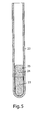
- a ballast inside said tubular shell a ballast can be arranged and preferably, above said ballast, a cap can be arranged being provided on its side surfaces with watertight elements for the walls of said tubular shell.
- the low enthalpy vertical geothermal probe according to the present invention can be applied in any position both inside and outside a site, and its installation depth, varying from a few meters to one hundred meters, and beyond, allows for making the boreholes needed for installation without any need to make specific preliminary geological survey.
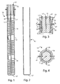
- a low enthalpy vertical geothermal probe is made of a coil pipe 11, a tubular shell 12, open on the top and provided with a closed bottom 12', arranged for protecting said coil pipe 11, and an upper closing element 13, sealingly matching with said tubular shell 12, more in detail in correspondence of its open top, and provided with openings 14, 15 for the passage of the coil pipe 11 and optionally of an additional opening 16 of inspection and insertionor removal of material (in particular of a liquid that preferably is a solution of water and ethylene glycol) inside the probe 10. All of said openings are provided wit closing caps 17.
- said coil pipe 11 is preferably made in copper and is composed of an elicoidal portion 11' inside which a fluid flows downwards and of a straight portion 11 ", arranged within the coils of said elicoidal portion 11', inside which a fluid flows upwards.
- the fluid flowing inside the coil pipe 11 is, according to a particularly preferred embodiment of the present invention, a cooling gas, even if it is possible to use within this pipe also a thermal exchange fluid, as already specified earlier for those cases in which it is desirable to use the vertical geothermal probe according to the present invention in a previously installed geothermal plant according to the prior art and making minimal changes to said plant.
- the straight portion 11" of the coil pipe 11 is coated with a pipe 18 made of insulating materiall, in particular polyethylene, to avoid, in summer, an even only partial reabsorption of the heat previously released and, therefore, maintaining a high differential between the gas inlet temperature and the gas outlet temperature.
- insulating materiall in particular polyethylene
- the tubular shell 12 is made of an insulating material, both thermally and galvanically, and is preferably high density polyethylene (HDPE). Structurally, depending on the installation site and the diameter of the tubular shell, the shell is made of a single piece, or by a plurality of cylindrical portions welded head to head and to which the bottom 12' is welded.
- HDPE high density polyethylene
- the closing element 13 is made with the same material of the tubular shell 12 and is fixed to the tubular shell 12 itself by means of screws or bayonet.
- the ends of the two portions 11' and 11" of the coil pipe 11 are passed respectively in the openings 14, 15 for passing the coil pipe 11 and are fixed for example by compression ends (not shown).
- the optional additional opening 16 can be used in future for possibleinspections or for the insertion or removal of additional quantities of water - ethylene glycol solution. Therefore, during normal usage, such additional opening 16 is closed by the corresponding cap 17, as shown in particular with reference to figure 1 .
- the closing element 13 is made with the same material of the tubular shell 12.
- the shape of the closing element 13 is such to grant the watertight closure on the walls of the tubular shell 12.
- the closing element 13 is provided with a tubular housing 19, shaped so to allow the housing within the top of the walls of the tubular shell 12, in particular with a certain degree of interference between the internal surface of the tubular housing 19 and the internal surface of the top of the walls of the tubular shell 12.
- the sealing in correspondence of these surfaces is additionally granted by the presence of two sealing rings (o-rings 20), housed in specific seats obtained from the internal surface of the tubular housing 19.
- the sealinf between the closing element 13 and the tubular shell 12 prevents undesirable leakage of the solution contained inside the probe 10, and in particular prevents part of the solution can disperse by evaporation, spacially in summer.
- An additional advantage of said sealing is that of preventing possible infiltrations from the soil covering the probe, even if obvious considerations of correct design of the probe would suggest to make a inspection pit for possible future works of ordinary and extraordinary maintenance.
- the closing element 13 is additionally provided with a plurality of fixing screws 21, assuring the mechanical fixing of the closing element 13 on the tubular shell 12.
- the tubular shell 12 is put in the borehole, progressively adding inside it water or another suitable liquid, in order to ease the insertion due to the weight and therefore exploiting the force of gravity, without anyway the need of making use of ballasts, which are always applied in specific cases when it is required, for example when inside the borehole is present water.
- ballasts since the tubular shell is made of plastic material, even if it is filled with water it will tend to float.
- the ballasts according to the prior art present different drawbacks, because they must be applied on the exterior of the tubular shell, implying the possibility they can be catched and can not be found.
- tubular shell 12 When the tubular shell 12 is installed for all of its length its position is fixed by introducing in the interspace between the wall of the borehole and the external surface of the tubular shell 12 sand or concrete mixed with bentonite.
- the coil pipe 11 is introduced in it and then in the water previously poured in the tubular shell is added an antifreeze, in particular ethylene glycol, and possibly other water.
- an antifreeze in particular ethylene glycol, and possibly other water.
- the preferred amount of ethylene glycol in solution in water is 40% by weight. The function of this addition is that of preventing water can freeze in winter.
- the optimal level 22 of the solution of water and ethylene glycol within the probe 10 is not that of completly filling the tubular shell 12, but rather it is preferred to maintain such level 22 about 20 or 30 cm below the top of the tubular shell 12, i.e. below the closing element 13 of the probe 10 that will be added subsequently. In this way, the air above the liquid surface 22 allows for a better coibentation towards the exterior and allows for absorbing the dilatations of the liquid in the functioning due to temperature change within the probe 10.
- the closing element 13 is inserted on the tubular shell 12 and is fixed thereof by fixing screws 21 or by means of other suitable fixing devices (for example a bayonet).
- each geothermal probes 10 needed for the plant after the connection of the different probes 10 and of the probes with the rest of the geothermal plant (a refrigerating compressor or a heat pump or heat exchanger depending on the probes 10 being connected to a specifically made plant or to an already existing plant modified only by the addition of the probes) is completed.
- the preferred connection of the probes 10 is in parallel, because it allows for a more homogeneous distribution of each single probe 10 without intervening with gas control valves.
- each probe 10 offer the same resistance to the fluid flowing within the respective coil pipes 11, allowing for a perfectly identical distribution and allowing for the optimal workong of all the probes 10.
- the advantages of the low enthalpy vertical geothermal probe according to the present invention will be immediately evident for a person skilled in the art.
- the proposed solution allows for making a plant allowing the maximum of efficiency with the lower possible costs.
- the making of the plant according to the proposed solution prevents possible drawbacks due to gas leakages and subsequently the need for maintenance or substitution of components of the plant.
Landscapes
- Engineering & Computer Science (AREA)
- Life Sciences & Earth Sciences (AREA)
- Sustainable Development (AREA)
- Sustainable Energy (AREA)
- Chemical & Material Sciences (AREA)
- Combustion & Propulsion (AREA)
- Mechanical Engineering (AREA)
- General Engineering & Computer Science (AREA)
- Geophysics And Detection Of Objects (AREA)
- Hydrogenated Pyridines (AREA)
Applications Claiming Priority (1)
| Application Number | Priority Date | Filing Date | Title |
|---|---|---|---|
| ITRM2011A000025A IT1404747B1 (it) | 2011-01-24 | 2011-01-24 | Sonda geotermica verticale a bassa entalpia. |
Publications (2)
| Publication Number | Publication Date |
|---|---|
| EP2503262A2 true EP2503262A2 (fr) | 2012-09-26 |
| EP2503262A3 EP2503262A3 (fr) | 2014-03-12 |
Family
ID=43975554
Family Applications (1)
| Application Number | Title | Priority Date | Filing Date |
|---|---|---|---|
| EP12425011.9A Withdrawn EP2503262A3 (fr) | 2011-01-24 | 2012-01-20 | Sonde géothermique verticale d'enthalpie basse |
Country Status (2)
| Country | Link |
|---|---|
| EP (1) | EP2503262A3 (fr) |
| IT (1) | IT1404747B1 (fr) |
Cited By (2)
| Publication number | Priority date | Publication date | Assignee | Title |
|---|---|---|---|---|
| GB2509537A (en) * | 2013-01-08 | 2014-07-09 | David John Trotman | Geothermal Ground Loop Heat Exchanger for Circulating Heat Pump Systems |
| EP4632289A1 (fr) * | 2024-04-11 | 2025-10-15 | Kerstin Dube | Absorbeur de chaleur géothermique et son procédé de fabrication |
Family Cites Families (6)
| Publication number | Priority date | Publication date | Assignee | Title |
|---|---|---|---|---|
| DE1601325A1 (de) * | 1968-01-05 | 1971-01-07 | Schantz Dipl Ing Hugo | Verdampferaggregat einer Waermepumpenanlage fuer eine kombinierte Luftheizung und Warmwasserbereitung |
| FR2357721A1 (fr) * | 1976-07-09 | 1978-02-03 | Vignal Maurice | Procede de preparation d'un trou fore dans le sol pour constituer un echangeur geothermique pour les installations de chauffage |
| WO2008014848A2 (fr) * | 2006-06-20 | 2008-02-07 | Eckhard Meyer-Rieke | Sonde enterree sous la forme d'un systeme a double tube destinee a utiliser l'energie geothermique pour le fonctionnement de pompes a chaleur |
| JP2009103367A (ja) * | 2007-10-23 | 2009-05-14 | Daiwa House Ind Co Ltd | 地中との熱交換のための構造 |
| JP5297044B2 (ja) * | 2008-01-10 | 2013-09-25 | Jfeスチール株式会社 | 地中熱交換器 |
| JP4636205B2 (ja) * | 2008-12-19 | 2011-02-23 | ダイキン工業株式会社 | 地中熱交換器及びそれを備えた空調システム |
-
2011
- 2011-01-24 IT ITRM2011A000025A patent/IT1404747B1/it active
-
2012
- 2012-01-20 EP EP12425011.9A patent/EP2503262A3/fr not_active Withdrawn
Non-Patent Citations (1)
| Title |
|---|
| None |
Cited By (2)
| Publication number | Priority date | Publication date | Assignee | Title |
|---|---|---|---|---|
| GB2509537A (en) * | 2013-01-08 | 2014-07-09 | David John Trotman | Geothermal Ground Loop Heat Exchanger for Circulating Heat Pump Systems |
| EP4632289A1 (fr) * | 2024-04-11 | 2025-10-15 | Kerstin Dube | Absorbeur de chaleur géothermique et son procédé de fabrication |
Also Published As
| Publication number | Publication date |
|---|---|
| ITRM20110025A1 (it) | 2012-07-25 |
| IT1404747B1 (it) | 2013-11-29 |
| EP2503262A3 (fr) | 2014-03-12 |
Similar Documents
| Publication | Publication Date | Title |
|---|---|---|
| RU2421666C2 (ru) | Труба и система для использования низкотемпературной энергии | |
| US7234314B1 (en) | Geothermal heating and cooling system with solar heating | |
| Zheng et al. | The thermal performance of seawater-source heat pump systems in areas of severe cold during winter | |
| RU2429428C2 (ru) | Система и распределительная цистерна для сети низкотемпературной энергии | |
| AU2003257096B2 (en) | Sealed well direct expansion heating and cooling system | |
| US7363769B2 (en) | Electromagnetic signal transmission/reception tower and accompanying base station employing system of coaxial-flow heat exchanging structures installed in well bores to thermally control the environment housing electronic equipment within the base station | |
| US7343753B2 (en) | Coaxial-flow heat transfer system employing a coaxial-flow heat transfer structure having a helically-arranged fin structure disposed along an outer flow channel for constantly rotating an aqueous-based heat transfer fluid flowing therewithin so as to improve heat transfer with geological environments | |
| RU2561840C2 (ru) | Подземный контур в системе низкотемпературной энергии и способ ее получения | |
| US9085412B1 (en) | Underground storage heating and cooling (USHC) system | |
| ES2549627T3 (es) | Sonda geotérmica de circuito cerrado | |
| US20100193152A1 (en) | Sawyer-singleton geothermal energy tank | |
| US20150345873A1 (en) | Underground storage heating and cooling (ushc) system | |
| EP2503262A2 (fr) | Sonde geothermique verticale d'enthalpie basse | |
| US11549693B2 (en) | Hot water tank | |
| CA2747464A1 (fr) | Systeme de transfert d'energie geothermique | |
| CN101375113B (zh) | 利用低能的管道和系统 | |
| ES3054288T3 (en) | Underground ice storage system in aquifers and aquitards for supplying heat | |
| GB1563076A (en) | Heat accumulators | |
| JP6303361B2 (ja) | 採熱井及び融雪方法 | |
| KR101612905B1 (ko) | 지중열 축열을 위한 파일 집합체 | |
| JP6349078B2 (ja) | 熱源水及び循環水熱交換システム | |
| KR101637528B1 (ko) | 지열 회수를 통한 급탕수 공급장치 | |
| RU2517844C2 (ru) | Устройство теплообмена жидкостей и газов | |
| ITRM20120176A1 (it) | Sonda geotermica verticale a bassa entalpia. | |
| ES2475992A1 (es) | Sistema interacumulador para la obtención de agua caliente por medio de un intercambiador de calor |
Legal Events
| Date | Code | Title | Description |
|---|---|---|---|
| PUAI | Public reference made under article 153(3) epc to a published international application that has entered the european phase |
Free format text: ORIGINAL CODE: 0009012 |
|
| AK | Designated contracting states |
Kind code of ref document: A2 Designated state(s): AL AT BE BG CH CY CZ DE DK EE ES FI FR GB GR HR HU IE IS IT LI LT LU LV MC MK MT NL NO PL PT RO RS SE SI SK SM TR |
|
| AX | Request for extension of the european patent |
Extension state: BA ME |
|
| PUAL | Search report despatched |
Free format text: ORIGINAL CODE: 0009013 |
|
| AK | Designated contracting states |
Kind code of ref document: A3 Designated state(s): AL AT BE BG CH CY CZ DE DK EE ES FI FR GB GR HR HU IE IS IT LI LT LU LV MC MK MT NL NO PL PT RO RS SE SI SK SM TR |
|
| AX | Request for extension of the european patent |
Extension state: BA ME |
|
| RIC1 | Information provided on ipc code assigned before grant |
Ipc: F24J 3/08 20060101AFI20140205BHEP |
|
| STAA | Information on the status of an ep patent application or granted ep patent |
Free format text: STATUS: THE APPLICATION IS DEEMED TO BE WITHDRAWN |
|
| 18D | Application deemed to be withdrawn |
Effective date: 20140913 |