EP2503302A2 - Kalibration und Korrektur eines Kreisels - Google Patents
Kalibration und Korrektur eines Kreisels Download PDFInfo
- Publication number
- EP2503302A2 EP2503302A2 EP12004709A EP12004709A EP2503302A2 EP 2503302 A2 EP2503302 A2 EP 2503302A2 EP 12004709 A EP12004709 A EP 12004709A EP 12004709 A EP12004709 A EP 12004709A EP 2503302 A2 EP2503302 A2 EP 2503302A2
- Authority
- EP
- European Patent Office
- Prior art keywords
- sensor
- accelerometer
- information
- data
- gyroscope
- Prior art date
- Legal status (The legal status is an assumption and is not a legal conclusion. Google has not performed a legal analysis and makes no representation as to the accuracy of the status listed.)
- Withdrawn
Links
- 238000012937 correction Methods 0.000 title description 2
- 238000005259 measurement Methods 0.000 claims abstract description 111
- 238000012545 processing Methods 0.000 claims abstract description 41
- 230000033001 locomotion Effects 0.000 claims abstract description 30
- 230000008859 change Effects 0.000 claims abstract description 25
- 238000000034 method Methods 0.000 claims description 74
- 238000004891 communication Methods 0.000 claims description 18
- 230000001133 acceleration Effects 0.000 claims description 7
- 238000006073 displacement reaction Methods 0.000 claims description 4
- 238000010586 diagram Methods 0.000 description 29
- 230000008569 process Effects 0.000 description 26
- 239000000872 buffer Substances 0.000 description 15
- 230000015654 memory Effects 0.000 description 13
- 230000004044 response Effects 0.000 description 11
- 230000006870 function Effects 0.000 description 10
- 238000005516 engineering process Methods 0.000 description 9
- 230000000694 effects Effects 0.000 description 8
- 230000005540 biological transmission Effects 0.000 description 5
- 239000011159 matrix material Substances 0.000 description 5
- 230000036772 blood pressure Effects 0.000 description 4
- 238000001514 detection method Methods 0.000 description 4
- 230000000737 periodic effect Effects 0.000 description 4
- 230000010354 integration Effects 0.000 description 3
- 238000003032 molecular docking Methods 0.000 description 3
- 230000003321 amplification Effects 0.000 description 2
- 230000003139 buffering effect Effects 0.000 description 2
- 230000001413 cellular effect Effects 0.000 description 2
- 230000003750 conditioning effect Effects 0.000 description 2
- 238000005314 correlation function Methods 0.000 description 2
- 239000013078 crystal Substances 0.000 description 2
- 230000014509 gene expression Effects 0.000 description 2
- 230000005484 gravity Effects 0.000 description 2
- 230000000977 initiatory effect Effects 0.000 description 2
- 238000012986 modification Methods 0.000 description 2
- 230000004048 modification Effects 0.000 description 2
- 238000003199 nucleic acid amplification method Methods 0.000 description 2
- 230000002093 peripheral effect Effects 0.000 description 2
- 230000001360 synchronised effect Effects 0.000 description 2
- 230000007704 transition Effects 0.000 description 2
- 238000013519 translation Methods 0.000 description 2
- 230000001960 triggered effect Effects 0.000 description 2
- 238000012935 Averaging Methods 0.000 description 1
- WQZGKKKJIJFFOK-GASJEMHNSA-N Glucose Natural products OC[C@H]1OC(O)[C@H](O)[C@@H](O)[C@@H]1O WQZGKKKJIJFFOK-GASJEMHNSA-N 0.000 description 1
- 230000032683 aging Effects 0.000 description 1
- 238000003491 array Methods 0.000 description 1
- 230000000386 athletic effect Effects 0.000 description 1
- 239000008280 blood Substances 0.000 description 1
- 210000004369 blood Anatomy 0.000 description 1
- 238000009529 body temperature measurement Methods 0.000 description 1
- 238000013461 design Methods 0.000 description 1
- 238000001914 filtration Methods 0.000 description 1
- 239000008103 glucose Substances 0.000 description 1
- 230000002401 inhibitory effect Effects 0.000 description 1
- 238000009434 installation Methods 0.000 description 1
- 230000007774 longterm Effects 0.000 description 1
- 238000012423 maintenance Methods 0.000 description 1
- 238000010295 mobile communication Methods 0.000 description 1
- 230000003287 optical effect Effects 0.000 description 1
- 238000013450 outlier detection Methods 0.000 description 1
- 238000007781 pre-processing Methods 0.000 description 1
- 238000005070 sampling Methods 0.000 description 1
- 239000004065 semiconductor Substances 0.000 description 1
- 230000035945 sensitivity Effects 0.000 description 1
- 230000011664 signaling Effects 0.000 description 1
- 230000006641 stabilisation Effects 0.000 description 1
- 238000011105 stabilization Methods 0.000 description 1
Images






Classifications
-
- G—PHYSICS
- G01—MEASURING; TESTING
- G01C—MEASURING DISTANCES, LEVELS OR BEARINGS; SURVEYING; NAVIGATION; GYROSCOPIC INSTRUMENTS; PHOTOGRAMMETRY OR VIDEOGRAMMETRY
- G01C21/00—Navigation; Navigational instruments not provided for in groups G01C1/00 - G01C19/00
- G01C21/10—Navigation; Navigational instruments not provided for in groups G01C1/00 - G01C19/00 by using measurements of speed or acceleration
- G01C21/12—Navigation; Navigational instruments not provided for in groups G01C1/00 - G01C19/00 by using measurements of speed or acceleration executed aboard the object being navigated; Dead reckoning
- G01C21/16—Navigation; Navigational instruments not provided for in groups G01C1/00 - G01C19/00 by using measurements of speed or acceleration executed aboard the object being navigated; Dead reckoning by integrating acceleration or speed, i.e. inertial navigation
- G01C21/183—Compensation of inertial measurements, e.g. for temperature effects
-
- G—PHYSICS
- G01—MEASURING; TESTING
- G01C—MEASURING DISTANCES, LEVELS OR BEARINGS; SURVEYING; NAVIGATION; GYROSCOPIC INSTRUMENTS; PHOTOGRAMMETRY OR VIDEOGRAMMETRY
- G01C25/00—Manufacturing, calibrating, cleaning, or repairing instruments or devices referred to in the other groups of this subclass
- G01C25/005—Manufacturing, calibrating, cleaning, or repairing instruments or devices referred to in the other groups of this subclass initial alignment, calibration or starting-up of inertial devices
Definitions
- the subject matter disclosed herein relates to the collection and/or processing of sensor data from multiple sensors.
- sensors are available to support a number of applications in today's market. These sensors may convert physical phenomena into analog and/or electrical signals. Such sensors may include, for example, a barometric pressure sensor.
- a barometric pressure sensor may be used to measure atmospheric pressure. Applications for the barometric pressure sensor may include determining altitude. Other applications may include observing atmospheric pressure as it relates to weather conditions.
- Another sensor type may include an accelerometer.
- An accelerometer may sense the direction of gravity and any other force experienced by the sensor.
- the accelerometer may be used to sense linear and/or angular movement, and may also be used, for example, to measure tilt and/or roll.
- Yet another sensor type may include a gyroscope which measures the Coriolis effect and may be used in applications measuring heading changes or in measuring rate of rotation. Gyroscopes have, for example, important applications in the field of navigation.
- Another type of sensor may include a magnetic field sensor that may measure the strength of a magnetic field and, correspondingly, the direction of a magnetic field.
- a compass is an example of a magnetic field sensor. The compass may find use in determining absolute heading in car and pedestrian navigation applications.
- Biometric sensors represent another type of sensors that may have a variety of possible applications. Some examples of biometric sensors may include heart rate monitors, blood pressure monitors, fingerprint detection, touch (heptic) sensors, blood sugar (glucose) level measuring sensors, etc.
- accelerometers may be utilized individually or may be used in combination with other sensors, depending on the particular application.
- accelerometers may be utilized to provide adequate degrees of observability.
- the accelerometer and gyroscope may provide six axes of observability (x, y, z, ⁇ , ⁇ , ⁇ ).
- the accelerometer may sense linear motion (translation in any plane, such as a local horizontal plane). This translation may be measured with reference to at least one axis.
- the accelerometer may also provide a measure of an object's tilt (roll or pitch).
- an object's motion in Cartesian coordinate space (x, y, z) may be sensed, and the direction of gravity may be sensed to estimate an object's roll and pitch.
- the gyroscope may be used to measure the rate of rotation about (x, y, z), i.e., roll ( ⁇ ) and pitch ( ⁇ ) and yaw, which may also be referred to as azimuth or "heading" ( ⁇ ).
- Navigational applications are merely one example of how more than one sensor type may be utilized in combination to provide multi-axes measurement capabilities.
- the utilization of multiple sensors to perform measurements may present a number of challenges to users of these devices. Such challenges may include, for example, size, cost, interfaces, connectivity, and/or power consumption of the multiple sensors.
- motion of a device may be detected in response to receipt of a signal from a first sensor disposed in the device, and a power state of a second sensor also disposed in the device may be changed in response to detected motion.
- FIG. 1 is a block diagram of an example multi-sensor measurement processing unit (MSMPU).
- MSMPU multi-sensor measurement processing unit
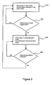
- FIG. 2 is a flow diagram of an example process for power managing a plurality of sensors integrated within a single device.
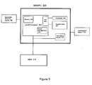
- FIG. 3 is a block diagram of an additional example of a multi-sensor measurement processing unit.
- FIG. 4 is a flow diagram of an example process for switching operational modes of a gyroscope in response to motion detected by an accelerometer.
- FIG. 5 is a block diagram of a further example of a multi-sensor measurement processing unit.
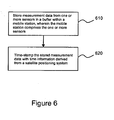
- FIG. 6 is a flow diagram of an example process for time-stamping buffered sensor data.
- FIG. 7 is a flow diagram of an example process for calibrating sensors.
- FIG. 8 is a flow diagram of an example process for determining whether a mobile station has entered or exited a specified region.
- FIG. 9 is a flow diagram of an example process for combining accelerator and gyroscope measurements.
- FIG. 10 is a block diagram of an additional example of an MSMPU.
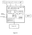
- FIG. 11 is a block diagram of an example mobile station incorporating an MSMPU.
- a processing unit may be implemented within one or more application specific integrated circuits (ASICs), digital signal processors (DSPs), digital signal processing devices (DSPDs), programmable logic devices (PLDs), field programmable gate arrays (FPGAs), processors, controllers, micro-controllers, microprocessors, electronic devices, other devices units designed to perform the functions described herein, and/or combinations thereof.
- ASICs application specific integrated circuits
- DSPs digital signal processors
- DSPDs digital signal processing devices
- PLDs programmable logic devices
- FPGAs field programmable gate arrays
- processors controllers, micro-controllers, microprocessors, electronic devices, other devices units designed to perform the functions described herein, and/or combinations thereof.
- Instructions relate to expressions which represent one or more logical operations.
- instructions may be "machine-readable” by being interpretable by a machine for executing one or more operations on one or more data objects.
- instructions as referred to herein may relate to encoded commands which are executable by a processing circuit having a command set which includes the encoded commands.
- Such an instruction may be encoded in the form of a machine language understood by the processing circuit. Again, these are merely examples of an instruction and claimed subject matter is not limited in this respect.
- Storage medium as referred to herein relates to media capable of maintaining expressions which are perceivable by one or more machines.
- a storage medium may comprise one or more storage devices for storing machine-readable instructions and/or information.
- Such storage devices may comprise any one of several media types including, for example, magnetic, optical or semiconductor storage media.
- Such storage devices may also comprise any type of long term, short term, volatile or non-volatile memory devices.
- these are merely examples of a storage medium, and claimed subject matter is not limited in these respects.
- Such actions and/or processes may be executed by a computing platform under the control of machine-readable instructions stored in a storage medium, for example.
- machine-readable instructions may comprise, for example, software or firmware stored in a storage medium included as part of a computing platform (e.g., included as part of a processing circuit or external to such a processing circuit).
- processes described herein, with reference to flow diagrams or otherwise may also be executed and/or controlled, in whole or in part, by such a computing platform.
- Wireless communication techniques described herein may be in connection with various wireless communication networks such as a wireless wide area network (WWAN), a wireless local area network (WLAN), a wireless personal area network (WPAN), and so on.
- WWAN wireless wide area network
- WLAN wireless local area network
- WPAN wireless personal area network
- a WWAN may be a Code Division Multiple Access (CDMA) network, a Time Division Multiple Access (TDMA) network, a Frequency Division Multiple Access (FDMA) network, an Orthogonal Frequency Division Multiple Access (OFDMA) network, a Single-Carrier Frequency Division Multiple Access (SC-FDMA) network, or any combination of the above networks, and so on.
- CDMA Code Division Multiple Access
- TDMA Time Division Multiple Access
- FDMA Frequency Division Multiple Access
- OFDMA Orthogonal Frequency Division Multiple Access
- SC-FDMA Single-Carrier Frequency Division Multiple Access
- a CDMA network may implement one or more radio access technologies (RATs) such as cdma2000, Wideband-CDMA (W-CDMA), to name just a few radio technologies.
- RATs radio access technologies
- cdma2000 may include technologies implemented according to IS-95, IS-2000, and IS-856 standards.
- a TDMA network may implement Global System for Mobile Communications (GSM), Digital Advanced Mobile Phone System (D-AMPS), or some other RAT.
- GSM and W-CDMA are described in documents from a consortium named "3rd Generation Partnership Project” (3GPP).
- Cdma2000 is described in documents from a consortium named "3rd Generation Partnership Project 2" (3GPP2).
- 3GPP and 3GPP2 documents are publicly available.
- a WLAN may comprise an IEEE 802.11 x network
- a WPAN may comprise a Bluetooth network, an IEEE 802.15x, for example.
- Wireless communication implementations described herein may also be used in connection with any combination of WWAN, WLAN and/or WPAN.
- a device and/or system may estimate its location based, at least in part, on signals received from satellites.
- a device and/or system may obtain "pseudorange" measurements comprising approximations of distances between associated satellites and a navigation satellite receiver.
- a pseudorange may be determined at a receiver that is capable of processing signals from one or more satellites as part of a Satellite Positioning System (SPS).
- SPS Satellite Positioning System
- Such an SPS may comprise, for example, a Global Positioning System (GPS), Galileo, Glonass, to name a few, or any SPS developed in the future.
- GPS Global Positioning System
- Galileo Galileo
- Glonass Glonass
- a satellite navigation receiver may obtain pseudorange measurements to three or more satellites as well as their positions at time of transmitting. Knowing the satellite's orbital parameters, these satellite positions can be calculated for any point in time. A pseudorange measurement may then be determined based, at least in part, on the time a signal travels from a satellite to the receiver, multiplied by the speed of light. While techniques described herein may be provided as implementations of location determination in a GPS, EGNOS, WAAS, Glonass and/or Galileo types of SPS as specific illustrations, it should be understood that these techniques may also apply to other types of SPS, and that claimed subject matter is not limited in this respect.
- Pseudolites may comprise ground-based transmitters that broadcast a PRN code or other ranging code (e.g., similar to a GPS or CDMA cellular signal) modulated on an L-band (or other frequency) carrier signal, which may be synchronized with GPS time.
- PRN code or other ranging code e.g., similar to a GPS or CDMA cellular signal
- L-band (or other frequency) carrier signal which may be synchronized with GPS time.
- Such a transmitter may be assigned a unique PRN code so as to permit identification by a remote receiver.
- Pseudolites may be useful in situations where SPS signals from an orbiting satellite might be unavailable, such as in tunnels, mines, buildings, urban canyons or other enclosed areas. Another implementation of pseudolites is known as radio-beacons.
- the term "satellite”, as used herein, is intended to include pseudolites, equivalents of pseudolites, and possibly others.
- SPS signals is intended to include SPS-like signals from pseudolites or equivalents of pseudolites.
- mobile station refers to a device that may from time to time have a position or location that changes.
- the changes in position and/or location may comprise changes to direction, distance, orientation, etc., as a few examples.
- a mobile station may comprise a cellular telephone, wireless communication device, user equipment, laptop computer, personal navigation device (PND), personal multimedia player (PMP), other personal communication system (PCS) device, and/or other portable communication device.
- PND personal navigation device
- PMP personal multimedia player
- PCS personal communication system
- a mobile station may also comprise a processor and/or computing platform adapted to perform functions controlled by machine-readable instructions.
- the utilization of multiple sensors to perform measurements may present a number of challenges to users of these devices.
- Such challenges may include, for example, size, cost, interfaces, connectivity, and/or power consumption of the multiple sensors.
- techniques described herein may include integrating two or more sensors in a single device.
- Such a device may comprise a component in a mobile station, for example.
- MSMPU multi-sensor measurement processing unit
- the MSMPU may support these applications by providing desirable signal amplification, conditioning, measurement collection, measurement preprocessing, power management of internal and/or external components (including externally connected or accessible sensors), and/or communication of raw and/or pre-processed sensor data to an external processor.
- the external processor may comprise, for example, a mobile station (MS) modem or any other processor.
- FIG. 1 is a block diagram of an example MSMPU 100 coupled to an MS modem (MSM) 110, which may comprise a processor.
- MSMPU 100 includes a pair of sensors, 130 and 140.
- a local processor 120 Also included in this example is a local processor 120.
- Sensor 130 and/or sensor 140 may comprise any of a wide range of sensor types, including, but not limited to, accelerometers, gyroscopes, geomagnetic, pressure, biometric, and temperature sensors, etc.
- local processor 120 may comprise a power management system comprising, for example, circuitry and/or may execute a power management program. Sensors 130 and 140 may transition between power stages under control of the power management system in order to selectively control power consumption in one or both sensors.
- sensor 130 may be placed in an "off” or “sleep mode” state where the sensor is drawing little or no power.
- Sensor 140 may operate in a low power mode, perhaps with limited functionality. Sensor 140 may at some point detect a trigger event. If sensor 140 detects a trigger event, local processor 120 may turn on sensor 130, and may also place sensor 140 in a normal operating mode. Alternatively, in another aspect, sensor 140 may operate in a normal mode while sensor 130 may be placed in an "off” or “low power mode” state. If sensor 140 detects a trigger event, local processor 120 may turn on sensor 130 and place it in a normal operating mode as well.
- the power management system may comprise dedicated logic in local processor 120.
- Dedicated logic may manage power on/off, reduced power operation, and/or sleep modes for various internal and/or external components.
- dedicated logic may provide power management for sensors 130 and 140.
- the power management system may be implemented at least in part as software instructions that are executable on local processor 120.
- Figure 2 is a flow diagram of an example process for power managing a pair of sensors situated within a mobile station.
- a first sensor is in a sleep mode or "off" mode, meaning that the first sensor is drawing little or no power.
- a second sensor is operating in a low-power mode.
- a determination may be made as to whether the second sensor has detected a trigger event.
- the first sensor may be placed into a normal operational mode and the second sensor may also be placed into a normal operational mode in order to perform a measurement activity. The two sensors may stay in the normal operational modes until the measurement activity is completed.
- the first sensor may be turned off or put in a "sleep" mode while the second sensor is placed into the low-power mode at block 210.
- Examples in accordance with claimed subject matter may include all, more than all, or less than all of blocks 210-240.
- the flow diagram of Figure 2 is merely an example technique for power managing a pair of sensors, and claimed subject matter is not limited in this respect.
- FIG. 3 is a block diagram of an example MSMPU 300 comprising a local processor 320, a memory 360, a power management unit 350, a gyroscope 330, and accelerometer 340, and a temperature sensor 335.
- MSMPU 300 may be coupled to an external processor, such as, for example, MSM 310.
- gyroscope 330 and/or accelerometer 340 may provide analog signals to local processor 320.
- MSMPU may comprise an analog-to-digital converter (A/D) 305 for digitizing analog signals from gyroscope 330, accelerometer 340, and/or other sensors.
- A/D analog-to-digital converter
- a geomagnetic sensor 370 and a barometric pressure sensor 380 are coupled to MSMPU 300.
- signal amplification and conditioning circuitry may be included to process externally connected analog sensors such as geomagnetic sensor 370.
- example MSMPU 300 is described with A/D 305 and memory 360 as being integrated within local processor 320, other examples are possible with one or both of A/D 305 and memory 360 not integrated within local processor 320. Further, the particular arrangement and configuration of MSMPU 300 is merely an example, and the scope of claimed subject matter is not limited in these respects.
- geomagnetic sensor 370 is not integrated into MSMPU 300, but is disposed elsewhere within the device incorporating MSMPU 300.
- the ability to position the geomagnetic sensor separately from MSMPU may allow for flexible placement of the geomagnetic sensor. Accordingly, such flexibility in placement of a geomagnetic sensor may enable greater flexibility in form factor design and placement to reduce the effects of electromagnetic interference and/or temperature, for example.
- external sensors 370 and/or 380 as well as MSM 310 may be coupled to MSMPU 300 via any of a wide range of interconnect types, including, but not limited to, 12C and/or SPI interconnects. Of course, this is merely an example interconnect type, and the scope of claimed subject matter is not limited in this respect.
- MSMPU 300 may implement an interrupt pin coupled to MSM 310 or another component. MSMPU 300 may operate the interrupt signal in a latched interrupt mode, for one example. Further, MSMPU 300 may incorporate an internal programmable threshold and dedicated circuitry to set the interrupt pin. However, these are merely examples of how interrupt signaling may be implemented, and the scope of claimed subject matter is not limited in this respect.
- MSMPU 300 may implement at least one general programmable IO pin (GPIO) coupled to MSM 310 or another component. MSMPU 300 may operate the GPIO pin to power on and off a connected component, for one example.
- GPIO general programmable IO pin
- power management unit 350 may provide power control signals to gyroscope 330 and accelerometer 340.
- Power management unit 350 may be implemented as dedicated circuitry, or may be implemented as software and/or firmware stored in memory 360 and executed by local processor 320.
- gyroscope 330 may be turned off while accelerometer 340 is operating in a low power mode. Accelerometer 340 may operate while in the low power mode to detect motion of the device incorporating the MSMPU 300. If motion is detected, accelerometer 340 may be put into a normal operational mode and gyroscope 330 may also be powered on and put into a normal operational mode. In one aspect, each of the sensors 330 and 340, as well as for some implementations external sensors such as geomagnetic sensor 370 and barometric sensor 380, may be powered on, put to sleep, put into low power operational modes, and/or put into normal operational modes independently of one another.
- MSMPU 300 may implement a fast procedure to restore power for gyroscope 330 and/or accelerometer 340.
- one of two or more fast procedures to restore power may be selected, wherein the different modes represent various compromises between wake up time and current consumption.
- the output of accelerometer 340 may be used as a switch to turn on other sensors integrated within MSMPU 300 or elsewhere within the device incorporating MSMPU 300.
- external sensors may be incorporated on the same die as MSMPU 300 or may be implemented as a single system-in-package (SIP).
- SIP system-in-package
- External sensors may also be situated outside of the device incorporating MSMPU 300, perhaps remotely connected with MSMPU 300 via a wireless interconnect, as described further below, or via another type of interconnect.
- sensors integrated within MSMPU 300 may have programmable and/or selectable characteristics.
- accelerometer 340 may implement a selectable "g" level, perhaps with a range of from 2 to 16g, in one example.
- gyroscope 330 may have a selectable angular velocity range, perhaps ranging from 50 to 500 deg/sec for one example.
- MSMPU 300 may incorporate a selectable output resolution for measurement data. In one example, resolutions of either seven bits for low power consumption modes or fourteen to sixteen bits for normal operational modes may be selected. Also, MSMPU may operate at a selectable bandwidth for the interface to MSM 310. For one example, the bandwidth may be selectable between 25 and 1500 Hz.
- MSMPU 300 and its associated sensors may be used in navigational applications.
- Accelerometer 340 may be pre-programmed and/or preconfigured to detect the movement (change in acceleration) and/or change in the tilt angle of the device incorporating MSMPU 300 as either exceeding, falling below, or being between two thresholds (upper and lower) to trigger power management functions for one or more of the other sensors.
- geomagnetic sensor 370 and/or gyroscope 330 and/or barometric pressure sensor 380 and/or a camera sensor (not shown) and/or any other sensor integrated into the device incorporating the MSMPU or remotely connected to the MSMPU can be powered on if motion is detected in order to perform the navigation application.
- the accelerometer output may be used to put any or all the other sensors in a sleep, low power, or off mode, thus reducing the power consumption.
- Figure 4 is a flow diagram of an example process for power managing two or more sensors including an accelerometer within a mobile station.
- one or more sensors are in a sleep mode, meaning that the one or more sensors are drawing little or no power.
- an accelerometer may operate in a low-power mode.
- Block 420 indicates that if the accelerometer detects movement, at block 430 the one or more sensors previously put in sleep mode may be wakened to operate in a normal operational mode.
- the accelerometer may also be put into a normal operational mode in order to perform a measurement activity in conjunction with the one or more other sensors, perhaps including a gyroscope and/or a geomagnetic sensor.
- the various sensors may stay in the normal operational modes until the measurement activity, perhaps including navigational operations for one example, is completed.
- the one or more sensors may be returned to sleep mode and the accelerometer may be placed into the low-power mode at block 410.
- Examples in accordance with claimed subject matter may include all, more than all, or less than all of blocks 410-440. Further, the flow diagram of Figure 4 is merely an-example technique, and claimed subject matter is not limited in this respect.
- accelerometer 340 may be used to detect a free-fall condition of the device incorporating the MSMPU, perhaps a mobile station, in order to power down gyroscope 330 to protect the gyroscope from damage upon impact. This process may be analogous to a process of parking a read/write head of a hard disk to protect it from impact of a fall.
- the power control logic implemented within MSMPU 300 may power on or off or switch the operational modes of not only the internal sensors such as accelerometer 340 and gyroscope 330, but may also power on or off or switch the operational modes of external sensors such as geomagnetic sensor 370 and barometric pressure sensor 380.
- power management unit 350 may also be adapted to power on or off or switch the operational modes of an external processor, such as, for one example, MSM 310.
- power management unit 350 may execute processes to determine conditions under which it may be advantageous to switch modes of operation for various internal and external sensors and/or processors and/or other components. Of course, these are merely examples of power management processes that may be executed by power management unit 350, and the scope of claimed subject matter is not limited in this respect.
- local processor 320 may be used to detect motion based on the measurements from at least one of accelerometer 340 and gyroscope 330. Furthermore, the motion detection event may be used to start the execution of the instructions resident on an external processor such as MSM310.
- FIG. 5 is a block diagram of an example MSMPU 500 coupled to a mobile station modem (MSM) 510.
- MSMPU 500 and MSM 510 may, for one example, be incorporated into a mobile station.
- MSMPU 500 may comprise a local processor 520, a memory 560, a power management unit 550, a gyroscope 530, an accelerometer 540, and a temperature sensor 535.
- gyroscope 530 and/or accelerometer 540 may provide analog signals to local processor 520.
- MSMPU may comprise an analog-to-digital converter (A/D) 505 for converting analog signals from gyroscope 530, accelerometer 540, and/or other sensors.
- A/D analog-to-digital converter
- power management unit 550 may provide power control signals to gyroscope 530 and accelerometer 540.
- Power management unit 550 may be implemented as dedicated circuitry, or may be implemented as software and/or firmware stored in memory 560 and executed by local processor 520.
- MSMPU 500 may further be coupled to a barometric pressure sensor 580 and a geomagnetic sensor 570, and may also receive a wheel tick/odometer signal 585 and an external clock signal 587.
- this is merely one example configuration of an MSMPU and associated sensors and signals, and the scope of claimed subject matter is not limited in this respect.
- MSMPU may comprise one or more buffers adapted to store data from sensors, and/or from local processor 520, and/or from an external processor such as MSM 510.
- MSMPU 500 may comprise a raw data buffer 522 and a processed data buffer 524.
- the buffering capability provided by buffers 522 and/or 524 may be used for various measurements being generated by various components included in and/or coupled to MSMPU 500. For example, a rate at which measurements may be obtained from one or more sensors may be different from a rate at which these measurements are either processed in by the local processor 520 and/or transmitted to an external component such as an external processor, perhaps MSM 510 in one example.
- measurement data from one or more sensors may be collected in one or more buffer in order to transmit the data to MSM 510 or other component in a burst fashion.
- raw data buffer 522 may be used to store data in its raw form (as delivered by one or more sensors) and the processed data buffer may be used for data that may have been processed in some fashion either by local processor 520 or by an external processor such as MSM 510.
- processing may include any type of filtering, averaging, sub-sampling, outlier detection, and/or time stamping the data to associate an instance of time with one or more measurements.
- the buffering techniques described herein are merely example techniques, and the scope of claimed subject matter is not limited in this respect.
- Yet another aspect may comprise the time stamping of various sensor measurements upon storing the measurements in a buffer, such as, for example, either buffer 522 or buffer 524, or upon storing the measurements in a memory, such as, for example, memory 560.
- Measurement data may also be time-stamped upon transmitting the measurement data to an external component, such as, for example, MSM 510.
- the time stamping may be based, in an example, upon a clock signal received over external clock signal 587.
- external clock signal 587 may be generated by any of various common crystals, for example a 32 KHz crystal.
- the external clock signal may also be used by local phase-locked loop (PLL) circuitry to synthesize the higher frequency signal needed to run the local processor.
- PLL phase-locked loop
- a periodic time reference pulse may be accepted by MSMSPU 500 from MSM 510 or other external processor which has access to a reference time standard such as that provided by an SPS, or by the Coordinated Universal Time (UTC) standard, or by any other well known system time.
- Buffer data may be time-stamped with information derived from such system time information, for example time information derived from an SPS.
- time stamps may be synchronized to a reference time that may enable a combination of sensor data with other time-stamped data, such as SPS satellite measurements for navigation applications.
- an external processor for example, a client for sensor information
- start and stop times may correspond to sequential SPS measurement time tags and may be used to synchronize the sensor data to the received SPS data.
- SPS time tags to define a measurement period is merely one example technique, and time tags from a number of different sources may be used to define measurement time periods in other examples.
- Figure 6 is a flow diagram of an example process for time-stamping measurement data.
- measurement data from one or more sensors may be stored in a buffer within a mobile station, wherein the mobile station comprises the one or more sensors.
- the stored measurement data may be time-stamped with time information derived from a satellite positioning system or any other common reference system. Examples in accordance with claimed subject matter may include all, more than all, or less than all of blocks 610-620. Further, the flow diagram of Figure 6 merely illustrates an example technique, and claimed subject matter is not limited in this respect.
- a periodic time reference pulse signal such as that received via external clock 587 or via an SPS or other time pulse source may be used to initiate a transmission of sensor data from buffers 522 and/or 524 or from memory 560 to an external component such as MSM 510.
- MSMPU 500 may process sensor measurements according to desired processes, store the sensor data either in one or both of buffers 522 and 524 or in memory 560, and then transmit the sensor data in response to receiving the periodic time reference signal or in response to receiving a "ready to receive" message from an external component, such as, for example, MSM 510 or from a device in communication with MSM 510.
- initiation to transmit may be triggered by a receipt of a "ready to receive" message over any common I/O peripheral or interface such as 12C, SPI, UART, parallel port, etc.
- same peripherals and/or interfaces may be used to provide the external timing information to MSMPU 500 for measurement time stamping and/or maintenance of the synchronization between MSMPU 500 and external component such as MSM 510.
- circuitry and/or software may be provided to calibrate sensors either integrated within MSMPU 500 and/or externally connected to MSMPU 500.
- an external processor such as MSM 510 is used to execute a navigation application
- the navigation application may estimate one or more states associated with an object such as a mobile station.
- the one or more states may include, but are not limited to, geographic location, altitude, speed, heading, orientation, and/or the like.
- the one or more estimated states may provide information that may be used to calibrate various parameters of sensors incorporated within the mobile station.
- Such parameters may include accelerometer bias, drift, bias as a function of temperature, drift as a function of temperature, measurement noise as a function of temperature, sensitivity as a function of temperature, variation in any of the parameters as a result sensor installation (mounting) on the board or aging, etc.
- accelerometer bias drift
- bias bias as a function of temperature
- drift drift as a function of temperature
- measurement noise as a function of temperature
- sensitivity as a function of temperature
- variation in any of the parameters as a result sensor installation (mounting) on the board or aging, etc.
- Figure 7 is a flow diagram of an example process for calibrating a sensor.
- a change in at least one of position, velocity and altitude for a mobile station may be measured using one or more sensors integrated into the mobile station.
- the change in position may be measured, for an example, measuring a direction and/or distance traveled for the mobile station.
- a change in position for the mobile station may be measured using information from a satellite positioning system at 720.
- an error value may be calculated wherein the error value represents a difference between the measurements obtained by the one or more sensors and the measurements obtained via the satellite positioning system.
- the one or more sensors may be calibrated based at least in part on the error value. Examples in accordance with claimed subject matter may include all, more than all, or less than all of blocks 710-740. Further, the flow diagram of Figure 7 merely illustrates an example technique for calibrating a sensor, and claimed subject matter is not limited in this respect.
- circuitry and/or software and/or firmware may be provided to allow a determination that the device incorporating MSMPU 500 is stationary.
- the determination may be performed by software and/or firmware executed on local processor 520 or may be provided via an external input.
- a wheel tick/odometer input signal 585 may indicate a stationary condition.
- wheel tick/odometer input signal 585 may be used in performing sensor calibration processes.
- the stationary condition may be used to calibrate gyroscope 530 and/or barometric pressure sensor 580. If the device incorporating MSMPU 500 is known to be stationary, any change in pressure can be attributed to the actual variation in pressure and not to a change in altitude.
- MSMPU may be incorporated into any of a range of devices, including, for example, cell phones, personal digital assistants, notebook computers, etc. Such devices may on occasion be placed into a cradle or docking station. In one example, when such a device is placed in the cradle or docking station, the device is stationary. MSMPU 500 may sense or may receive an indication that such a device is placed in the cradle or docking station, deducing that the device is stationary. In an example, the indication of a stationary condition may be utilized in performing calibration operations such as discussed above. In another aspect, MSMPU 500 may detect the transition out of a stationary condition, for example through motion detection.
- temperature sensor 535 may provide temperature measurements that may be used in performing calibration operations in order to develop sensor performance characteristics as a function of temperature.
- a table of accelerometer drift values as a function of temperature may be learned and stored in memory 560.
- the sensor calibration data (such as bias and drift) may be provided to MSMPU 500 for sensor data correction. Correcting raw sensor data with calibration data may provide capabilities for various applications, including, but not limited to, motion detection and motion integration for dead-reckoning application.
- Dead reckoning (DR) may refer to a process of estimating one's current position and advancing that position based on known or measured speed, elapsed time, and heading.
- data from geometric sensor 570 may be used to calibrate gyroscope 530 biases and may also be used to initialize an absolute heading indicated by the geomagnetic sensor.
- geomagnetic sensor 570 may be tilt-compensated using roll and pitch measurements from accelerometer 540.
- Tilt-compensation processes may be implemented by dedicated circuitry resident on MSMPU 500 and/or may be implemented in software and/or firmware that may be executed by local processor 520 and/or MSMPU 500.
- the tilt-compensation processes may utilize measurement data received from externally connected geomagnetic sensor 570.
- gyroscope 530 may be calibrated using sequential and/or periodic and/or event-triggered measurements from geomagnetic sensor 570 to measure the change in the angular information.
- MSMPU 500 may perform motion integration by incorporating measurements from accelerometer 540 and gyroscope 530 to determine the change in the distance and direction traveled (e.g., trajectory or path of motion).
- This aspect may be advantageously employed in geo-fencing applications where it is desirable to determine if an object incorporating MSMPU 500 has exited or entered an area of interest.
- the area of interest may be defined as a circle with a preset and/or programmable radius, for an example, although this is merely an example of how an area of interest may be defined, and the scope of claimed subject matter is not limited in this respect.
- Figure 8 is a flow diagram illustrating an example geo-fence application.
- a starting position may be established for a mobile station.
- a change in position for the mobile station may be detected using accelerometer and gyroscope sensor data. The change in position may be detected, in an example, by detecting a direction and/or distance traveled for the mobile station using techniques known to those of ordinary skill in the art.
- a determination may be made as to whether the mobile station has exited or entered a specified region. Examples in accordance with claimed subject matter may include all, more than all, or less than all of blocks 810-830. Further, the flow diagram of Figure 8 merely illustrates an example technique for geo-fencing, and claimed subject matter is not limited in this respect.
- Figure 9 is a flow diagram of an example process for combining information from both accelerometer 540 and gyroscope 530.
- Such information may comprise motion integration and rotation data, and such information may be utilized to support geo-fencing and/or navigation DR operations.
- information from gyroscope 530 may be used to compute how much the mobile station's orientation has been rotated from the original orientation, in three dimensional space.
- the resulting rotation matrix may be used to convert the accelerometer information back to the measurement frame (orientation) that the accelerometer was in at the beginning of the measurement period.
- These "rotated" measurements may be added to previous measurements to determine a net displacement, because the measurements are all based on the same orientation.
- data may be acquired from a gyroscope, such as, for example gyroscope 530.
- 3x3 matrices may be created, and at block 925 individual roll, pitch, and yaw (heading) values may be summed.
- the matrices from block 910 may be multiplied at block 915 to accumulate the rotations.
- a matrix multiplied with the first rotation matrix may be identified.
- the matrix may be inverted to rotate the sample back to the start of the interval. Processing may proceed to block 940.
- accelerometer data (x, y, z) may be acquired, and at block 935 a 3x1 vector may be created.
- the inverted matrix from block 920 may be used to rotate the sample point back to the starting point.
- individual frames from within the same reference frame may be summed.
- the accumulated rotations (from gyroscope measurements) and distance traveled (from accelerometer measurements) may be combined. Examples in accordance with claimed subject matter may include all, more than all, or less than all of blocks 905-950. Further, the flow diagram of Figure 9 merely illustrates an example technique for combining accelerator and gyroscope measurements, and claimed subject matter is not limited in this respect.
- FIG 10 is a block diagram of an example MSMPU 1000 comprising wireless connectivity.
- MSMPU may comprise similar technologies as described above in connection with Figures 3 and 5 .
- Wireless connectivity may be accomplished via any of a wide range of wireless technologies, including future technologies. Bluetooth, ZigBee, Near Field Communication (NFC), WiFi, and Ultra Wide Band (UWB) are just a few examples of such wireless technologies, and the scope of claimed subject matter is not limited in this respect.
- These technologies are represented in Figure 10 by wireless communication units 1092, 1094, 1096, and 1098.
- a device integrating MSMPU 1000 may be able to communicate with another device which also includes an MSMPU 1084 for peer-to-peer applications such as multi-player games, as one example.
- MSMPU 1000 may also communicate with an external processor 1082 to provide processor 1082 with raw sensor measurements, processed sensor measurements, positional (x,y,z) and/or attitude information ( ⁇ , ⁇ , ⁇ ) in any number of degrees (depending on the availability and operational status of integrated or connected sensors), change in positional and/or attitude information, Euler angles, quaternion, telemetry data, etc.
- MSMPU 1000 may also communicate through any of the wireless technologies with one or more biometric sensors, such as, for example, heart rate monitor (HRM) 1086 and/or blood pressure (BP) monitor 1088.
- HRM heart rate monitor
- BP blood pressure monitor
- sensors may find application in medical and/or fitness/athletic fields, for example.
- Information gathered from internal and/or external sensors may be used by external processor 1082 to derive a navigational solution, and/or user interface and/or gaming control signals, camera image stabilization signals, etc.
- data from at least one MSMPU may be provided to a central processing unit to derive a relative positional and/or attitude information that may be used in a multi-player gaming environment where actions or change in position or change in attitude of one player with respect to another player are desirable to know.
- FIG. 11 is a block diagram of an example of a mobile station 1100.
- a radio transceiver 1170 may be adapted to modulate an RF carrier signal with baseband information, such as voice or data, onto an RF. carrier, and demodulate a modulated RF carrier to obtain such baseband information.
- An antenna 1172 may be adapted to transmit a modulated RF carrier over a wireless communications link and receive a modulated RF carrier over a wireless communications link.
- a baseband processor 1160 may be adapted to provide baseband information from a central processing unit (CPU) 1120 to transceiver 1170 for transmission over a wireless communications link.
- CPU 1120 may obtain such baseband information from an input device within a user interface 1110.
- Baseband processor 1160 may also be adapted to provide baseband information from transceiver 1170 to CPU 1120 for transmission through an output device within user interface 1110.
- User interface 1110 may comprise a plurality of devices for inputting or outputting user information such as voice or data.
- Such devices may include, by way of non-limiting examples, a keyboard, a display screen, a microphone, and a speaker.
- a receiver 1180 may be adapted to receive and demodulate transmissions from an SPS, and provide demodulated information to correlator 1140.
- Correlator 1140 may be adapted to derive correlation functions from the information provided by receiver 1180.
- Correlator 1140 may also be adapted to derive pilot-related correlation functions from information relating to pilot signals provided by transceiver 1170. This information may be used by a mobile station to acquire wireless communications services.
- Channel decoder 1150 may be adapted to decode channel symbols received from baseband processor 1160 into underlying source bits. In one example where channel symbols comprise convolutionally encoded symbols, such a channel decoder may comprise a Viterbi decoder. In a second example, where channel symbols comprise serial or parallel concatenations of convolutional codes, channel decoder 1150 may comprise a turbo decoder.
- a memory 1130 may be adapted to store machine-readable instructions which are executable to perform one or more of processes, implementations, or examples thereof which are described or suggested herein.
- CPU 1120 may be adapted to access and execute such machine-readable instructions.
- Mobile station 1100 for this example comprises an MSMPU 1190.
- MSMPU 1190 may be adapted to perform any or all of the sensor measurement and/or power management operations described herein.
- MSMPU 1190 may be adapted to perform the functions described above in connection with Figures 1-10 .
Landscapes
- Engineering & Computer Science (AREA)
- Radar, Positioning & Navigation (AREA)
- Remote Sensing (AREA)
- Physics & Mathematics (AREA)
- General Physics & Mathematics (AREA)
- Automation & Control Theory (AREA)
- Manufacturing & Machinery (AREA)
- Gyroscopes (AREA)
- Navigation (AREA)
Applications Claiming Priority (4)
| Application Number | Priority Date | Filing Date | Title |
|---|---|---|---|
| US89679507P | 2007-03-23 | 2007-03-23 | |
| US90938007P | 2007-03-30 | 2007-03-30 | |
| US91471607P | 2007-04-27 | 2007-04-27 | |
| EP08732773.0A EP2129999B1 (de) | 2007-03-23 | 2008-03-24 | Multisensor-datenerfassung und/oder -verarbeitung |
Related Parent Applications (2)
| Application Number | Title | Priority Date | Filing Date |
|---|---|---|---|
| EP08732773.0A Division EP2129999B1 (de) | 2007-03-23 | 2008-03-24 | Multisensor-datenerfassung und/oder -verarbeitung |
| EP08732773.0A Division-Into EP2129999B1 (de) | 2007-03-23 | 2008-03-24 | Multisensor-datenerfassung und/oder -verarbeitung |
Publications (2)
| Publication Number | Publication Date |
|---|---|
| EP2503302A2 true EP2503302A2 (de) | 2012-09-26 |
| EP2503302A3 EP2503302A3 (de) | 2014-08-06 |
Family
ID=46719995
Family Applications (1)
| Application Number | Title | Priority Date | Filing Date |
|---|---|---|---|
| EP12004709.7A Withdrawn EP2503302A3 (de) | 2007-03-23 | 2008-03-24 | Kalibration und Korrektur eines Kreisels |
Country Status (1)
| Country | Link |
|---|---|
| EP (1) | EP2503302A3 (de) |
Cited By (1)
| Publication number | Priority date | Publication date | Assignee | Title |
|---|---|---|---|---|
| US11099014B2 (en) * | 2016-10-18 | 2021-08-24 | Sony Semiconductor Solutions Corporation | Chip module, signal processing method, and electronic equipment |
Citations (1)
| Publication number | Priority date | Publication date | Assignee | Title |
|---|---|---|---|---|
| US3442140A (en) * | 1964-12-24 | 1969-05-06 | North American Rockwell | Drift rate compensation for acceleration sensitivity of an inertial navigation platform |
Family Cites Families (4)
| Publication number | Priority date | Publication date | Assignee | Title |
|---|---|---|---|---|
| JPH05172575A (ja) * | 1991-12-19 | 1993-07-09 | Pioneer Electron Corp | ナビゲーション装置 |
| JPH0731062B2 (ja) * | 1992-02-10 | 1995-04-10 | 住友電気工業株式会社 | ジャイロのオフセット補正方法及び装置 |
| US5859693A (en) * | 1997-08-26 | 1999-01-12 | Laser Technology, Inc. | Modularized laser-based survey system |
| KR100571795B1 (ko) * | 2004-02-06 | 2006-04-18 | 삼성전자주식회사 | 복각 검출 기능을 지원하는 지자기 센서 및 그 방법 |
-
2008
- 2008-03-24 EP EP12004709.7A patent/EP2503302A3/de not_active Withdrawn
Patent Citations (1)
| Publication number | Priority date | Publication date | Assignee | Title |
|---|---|---|---|---|
| US3442140A (en) * | 1964-12-24 | 1969-05-06 | North American Rockwell | Drift rate compensation for acceleration sensitivity of an inertial navigation platform |
Cited By (1)
| Publication number | Priority date | Publication date | Assignee | Title |
|---|---|---|---|---|
| US11099014B2 (en) * | 2016-10-18 | 2021-08-24 | Sony Semiconductor Solutions Corporation | Chip module, signal processing method, and electronic equipment |
Also Published As
| Publication number | Publication date |
|---|---|
| EP2503302A3 (de) | 2014-08-06 |
Similar Documents
| Publication | Publication Date | Title |
|---|---|---|
| US11659996B2 (en) | Multi-sensor data collection and/or processing | |
| JP2012150115A5 (de) | ||
| JP2012150116A5 (de) | ||
| US11971498B2 (en) | Hybrid positioning method, electronic apparatus and computer-readable recording medium thereof | |
| US9810536B2 (en) | Method and apparatus for accurate acquisition of inertial sensor data | |
| CN107422355B (zh) | 混合定位方法和电子装置 | |
| US8630798B2 (en) | Electronic system and method for personal navigation | |
| EP2503302A2 (de) | Kalibration und Korrektur eines Kreisels | |
| HK1140813A (en) | Multi-sensor data collection and/or processing |
Legal Events
| Date | Code | Title | Description |
|---|---|---|---|
| PUAI | Public reference made under article 153(3) epc to a published international application that has entered the european phase |
Free format text: ORIGINAL CODE: 0009012 |
|
| 17P | Request for examination filed |
Effective date: 20120622 |
|
| AC | Divisional application: reference to earlier application |
Ref document number: 2129999 Country of ref document: EP Kind code of ref document: P |
|
| AK | Designated contracting states |
Kind code of ref document: A2 Designated state(s): AT BE BG CH CY CZ DE DK EE ES FI FR GB GR HR HU IE IS IT LI LT LU LV MC MT NL NO PL PT RO SE SI SK TR |
|
| PUAL | Search report despatched |
Free format text: ORIGINAL CODE: 0009013 |
|
| AK | Designated contracting states |
Kind code of ref document: A3 Designated state(s): AT BE BG CH CY CZ DE DK EE ES FI FR GB GR HR HU IE IS IT LI LT LU LV MC MT NL NO PL PT RO SE SI SK TR |
|
| RIC1 | Information provided on ipc code assigned before grant |
Ipc: G01C 17/38 20060101ALI20140629BHEP Ipc: G01C 19/42 20060101ALI20140629BHEP Ipc: G01D 5/14 20060101AFI20140629BHEP Ipc: G01C 25/00 20060101ALI20140629BHEP Ipc: G01C 21/16 20060101ALI20140629BHEP |
|
| 17Q | First examination report despatched |
Effective date: 20170308 |
|
| GRAP | Despatch of communication of intention to grant a patent |
Free format text: ORIGINAL CODE: EPIDOSNIGR1 |
|
| INTG | Intention to grant announced |
Effective date: 20191025 |
|
| RAP1 | Party data changed (applicant data changed or rights of an application transferred) |
Owner name: QUALCOMM INCORPORATED |
|
| STAA | Information on the status of an ep patent application or granted ep patent |
Free format text: STATUS: THE APPLICATION IS DEEMED TO BE WITHDRAWN |
|
| 18D | Application deemed to be withdrawn |
Effective date: 20200305 |