EP2503328A1 - Appareil d'analyse et procédé d'analyse - Google Patents
Appareil d'analyse et procédé d'analyse Download PDFInfo
- Publication number
- EP2503328A1 EP2503328A1 EP12160935A EP12160935A EP2503328A1 EP 2503328 A1 EP2503328 A1 EP 2503328A1 EP 12160935 A EP12160935 A EP 12160935A EP 12160935 A EP12160935 A EP 12160935A EP 2503328 A1 EP2503328 A1 EP 2503328A1
- Authority
- EP
- European Patent Office
- Prior art keywords
- microchip
- unit
- cooling
- analysis
- voltage application
- Prior art date
- Legal status (The legal status is an assumption and is not a legal conclusion. Google has not performed a legal analysis and makes no representation as to the accuracy of the status listed.)
- Granted
Links
Images








Classifications
-
- G—PHYSICS
- G01—MEASURING; TESTING
- G01N—INVESTIGATING OR ANALYSING MATERIALS BY DETERMINING THEIR CHEMICAL OR PHYSICAL PROPERTIES
- G01N27/00—Investigating or analysing materials by the use of electric, electrochemical, or magnetic means
- G01N27/26—Investigating or analysing materials by the use of electric, electrochemical, or magnetic means by investigating electrochemical variables; by using electrolysis or electrophoresis
- G01N27/416—Systems
- G01N27/447—Systems using electrophoresis
- G01N27/44704—Details; Accessories
- G01N27/44708—Cooling
-
- B—PERFORMING OPERATIONS; TRANSPORTING
- B01—PHYSICAL OR CHEMICAL PROCESSES OR APPARATUS IN GENERAL
- B01D—SEPARATION
- B01D57/00—Separation, other than separation of solids, not fully covered by a single other group or subclass, e.g. B03C
- B01D57/02—Separation, other than separation of solids, not fully covered by a single other group or subclass, e.g. B03C by electrophoresis
-
- G—PHYSICS
- G01—MEASURING; TESTING
- G01N—INVESTIGATING OR ANALYSING MATERIALS BY DETERMINING THEIR CHEMICAL OR PHYSICAL PROPERTIES
- G01N27/00—Investigating or analysing materials by the use of electric, electrochemical, or magnetic means
- G01N27/26—Investigating or analysing materials by the use of electric, electrochemical, or magnetic means by investigating electrochemical variables; by using electrolysis or electrophoresis
- G01N27/416—Systems
- G01N27/447—Systems using electrophoresis
- G01N27/44756—Apparatus specially adapted therefor
- G01N27/44791—Microapparatus
-
- G—PHYSICS
- G01—MEASURING; TESTING
- G01N—INVESTIGATING OR ANALYSING MATERIALS BY DETERMINING THEIR CHEMICAL OR PHYSICAL PROPERTIES
- G01N27/00—Investigating or analysing materials by the use of electric, electrochemical, or magnetic means
- G01N27/26—Investigating or analysing materials by the use of electric, electrochemical, or magnetic means by investigating electrochemical variables; by using electrolysis or electrophoresis
- G01N27/416—Systems
- G01N27/447—Systems using electrophoresis
- G01N27/44704—Details; Accessories
- G01N27/44713—Particularly adapted electric power supply
-
- G—PHYSICS
- G01—MEASURING; TESTING
- G01N—INVESTIGATING OR ANALYSING MATERIALS BY DETERMINING THEIR CHEMICAL OR PHYSICAL PROPERTIES
- G01N27/00—Investigating or analysing materials by the use of electric, electrochemical, or magnetic means
- G01N27/26—Investigating or analysing materials by the use of electric, electrochemical, or magnetic means by investigating electrochemical variables; by using electrolysis or electrophoresis
- G01N27/416—Systems
- G01N27/447—Systems using electrophoresis
- G01N27/44704—Details; Accessories
- G01N27/44717—Arrangements for investigating the separated zones, e.g. localising zones
- G01N27/44721—Arrangements for investigating the separated zones, e.g. localising zones by optical means
Definitions
- the present invention relates to an analysis apparatus using electrophoresis and an analysis method.
- capillary electrophoresis is used in the fields of analytical biology and analytical biochemistry.
- Capillary electrophoresis is known as a representative example of electrophoresis (see, for example, JP 2001-99813A and JP 2003-166976A ).
- capillary electrophoresis a capillary (microtubule) filled with a buffer solution is used, and a sample is injected into the capillary. Furthermore, both ends of the capillary are immersed in the buffer solution, and in this condition, a voltage is applied inside the capillary.
- the sample Upon application of a voltage, the sample is separated while moving within the capillary. Then, the inside of the capillary is irradiated with, for example, ultraviolet rays, visible light, or infrared rays through a window provided partway along the capillary. Light transmitted through the capillary is received by a light receiving element, and thereafter analysis of the sample is conducted based on the received light, using absorptiometry.
- Microchips are generally made up of a glass substrate provided with fine grooves, and a cover bonded to the glass substrate so as to cover the grooves.
- the formation of grooves in the glass substrate is implemented by applying semiconductor manufacturing technology, and therefore, the width, depth, and number of grooves can be easily set. For this reason, microchips could play a leading role in electrophoresis in future.
- the temperature of the buffer solution needs to be managed so as to be kept within the optimal range during voltage application.
- most apparatuses for performing electrophoresis include an air blowing device and a Peltier element.
- capillaries since capillaries have low heat capacity, the inside of the capillaries can be easily kept within the optimal temperature range simply by operating a cooling apparatus.
- microchips because of their higher heat capacity as compared with capillaries, it is difficult to keep the inside of the microchips within the optimal temperature range simply by arranging and operating a cooling apparatus.
- the analysis apparatus is an analysis apparatus that performs electrophoresis using a microchip provided with a channel.
- the apparatus includes a cooling unit that cools the microchip, a voltage application unit that applies voltage to a buffer solution filled in the channel of the microchip, an optical analysis unit that conducts, through the microchip, optical analysis of a sample introduced in the channel, and a control unit that controls the cooling unit, the voltage application unit, and the optical analysis unit, wherein the control unit causes the cooling unit to start cooling the microchip, and after the microchip has been cooled, causes the voltage application unit and the optical analysis unit to operate.
- the microchip is sufficiently cooled in advance before execution of electrophoresis, and electrophoresis is executed thereafter.
- the present invention enables the temperature of the microchip to be optimized in electrophoresis using a microchip.
- control unit causes the voltage application unit and the optical analysis unit to operate, after a set period of time has elapsed since the cooling unit was caused to start cooling the microchip. In this mode, the microchip can be reliably cooled.
- the analysis apparatus further includes a temperature sensor for measuring a temperature of the microchip, wherein if the temperature measured by the temperature sensor is less than or equal to a first set temperature, the control unit causes the voltage application unit and the optical analysis unit to operate. In this mode, the microchip can be more reliably cooled because whether or not cooling is sufficient can be determined based on the temperature of the microchip.
- the control unit causes the cooling unit to stop cooling or reduce output. If the temperature within the channel of the microchip becomes too low, the viscosity of samples increases and electrophoresis becomes difficult, but such a situation can be avoided in the above mode.
- control unit causes the cooling unit to increase output immediately before causing the voltage application unit and the optical analysis unit to operate, and causes the cooling unit to reduce output after operations of the voltage application unit and the optical analysis unit have ended.
- a rise in the temperature of the microchip can be more strongly suppressed, and therefore it is easy to respond to an increase in the heating value of the microchip.
- the analysis apparatus further includes a first stage and a second stage on which the microchip is to be placed, wherein the cooling unit includes a first cooling unit that cools the microchip placed on the first stage, and a second cooling unit that cools the microchip placed on the second stage, the voltage application unit applies voltage to the microchip placed on the second stage, the optical analysis unit conducts optical analysis of the sample on the microchip placed on the second stage, while the microchip is placed on the first stage, the control unit cools the microchip with the first cooling unit, and when the microchip is thereafter placed on the second stage, the control unit executes voltage application by the voltage application unit and optical analysis by the optical analysis unit while cooling the microchip with the second cooling unit.
- the microchip to be measured next can be cooled in advance, thus improving the efficiency of measurement.
- the cooling unit is at least one of an air blowing device, an electron cooling element, and a heat pipe.
- the microchip prefferably includes a main body portion in which the channel is formed, and a heat radiation member provided on a surface of the main body portion, and the heat radiation member is formed from a material having higher thermal conductivity than a material forming the main body portion. In this case, cooling efficiency in the microchip can be improved.
- the microchip it is preferable for the microchip to include a main body portion in which the channel is formed, and a second channel for passing a cooling medium is further formed along the channel within the main body portion. In this case, the efficiency of cooling in the microchip can also be improved.
- An analysis method is an analysis method for performing an analysis of a sample through electrophoresis using a cooling apparatus, a voltage application apparatus, and an optical analysis apparatus, the cooling apparatus cooling a microchip provided with a channel, the voltage application apparatus applying voltage to a buffer solution filled in the channel of the microchip, and the optical analysis apparatus conducting, through the microchip, optical analysis of the sample that is introduced in the channel, the method comprising the steps of (a) cooling the microchip using the cooling apparatus, and (b) causing the voltage application apparatus and the optical analysis apparatus to operate, after the microchip has been cooled.
- a temperature sensor for measuring a temperature of the microchip is used, and in the step (b), if the temperature measured by the temperature sensor is less than or equal to a first set temperature, the voltage application apparatus and the optical analysis apparatus are caused to operate. Furthermore, in this mode, it is preferable for the method to further include the step of (c) if the temperature measured by the temperature sensor is less than or equal to a second set temperature, stopping the cooling apparatus from cooling the microchip or reducing output of the cooling apparatus.
- step (a) output of the cooling apparatus is increased immediately before the voltage application apparatus and the optical analysis apparatus are caused to operate, and in the step (b), the output of the cooling apparatus is reduced after operations of the voltage application apparatus and the optical analysis apparatus have ended.
- Embodiment 1 of the present invention will be described with reference to FIGS. 1 to 4 .
- FIG. 1 is a block diagram showing the configuration of the analysis apparatus according to Embodiment 1 of the present invention.
- the analysis apparatus 10 of Embodiment 1 is an analysis apparatus 10 that performs electrophoresis using a microchip 30.
- the microchip 30 is provided with a channel 32 in which a buffer solution is filled and furthermore a sample to be analyzed is injected.
- the analysis apparatus 10 also includes a cooling unit that cools the microchip 30, a voltage application unit that applies voltage to the buffer solution filled in the channel 32, an optical analysis unit that conducts, through the microchip 30, optical analysis of a sample introduced in the channel, and a control unit 20.
- the analysis apparatus 10 also includes a stage 11 on which the microchip 30 is to be placed.
- the cooling unit is a cooling apparatus that includes an electron cooling element 12 disposed between the stage 11 and the microchip 30, and a driving circuit 13 that drives the electron cooling element 12.
- the electron cooling element 12 is a Peltier element.
- the driving circuit 13 supplies current to the electron cooling element 12 in accordance with an instruction from the control unit 20, heat absorption by the electron cooling element 12 occurs and the microchip 30 is cooled.
- the cooling unit may be an air blowing device or a heat pipe, instead of the electron cooling element 12.
- the cooling unit may be an air blowing device or a heat pipe, instead of the electron cooling element 12.
- a form is possible in which a combination of at least two of the electron cooling element 12, an air blowing device, and a heat pipe is used as the cooling unit.
- the voltage application unit is a voltage application apparatus that includes a pair of electrodes 14a and 14b disposed at the respective ends of the channel 32, and a power supply circuit 15 that applies voltage between these electrodes.
- the power supply circuit 15 applies voltage between the electrodes 14a and 14b in accordance with an instruction from the control unit 20, electrophoresis occurs within the channel 32. In this case, heat is generated within the channel 32, and the temperature of the microchip 30 rises.
- the optical analysis unit is an optical analysis apparatus that includes a light source 16 that irradiates the channel 32 of the microchip 30 with light, a light receiving element 17 that receives light transmitted through the channel 32 and outputs a signal in accordance with the amount of the light received, and an analysis unit 18.
- the light receiving element 17 is disposed on the stage 11 such that its light receiving surface faces the microchip 30.
- the light source 16 is disposed above the microchip 30 such that its light emitting surface faces the microchip 30 on the stage 11.
- the analysis unit 18 measures the component quantity or component ratio of a target component based on the signal output from the light receiving element 17, and outputs the measurement result to the outside.
- the analysis unit 18 includes an arithmetic apparatus that executes, for example, absorptiometry based on the signal output from the light receiving element 17 and calculates the component quantity of a target component.
- the control unit 20 controls the cooling unit, the voltage application unit, and the optical analysis unit. Specifically, the control unit 20 instructs the driving circuit 13 to supply current, instructs the power supply circuit 15 to apply voltage, and instructs the light source 16 to perform light irradiation.
- the control unit 20 also causes the cooling unit to start cooling the microchip 30, and after the microchip 30 has been cooled, causes the voltage application unit and the optical analysis unit to operate. Specifically, when the analysis apparatus 10 is powered on, the control unit 20 first causes the driving circuit 13, which constitutes the cooling unit, to supply current. Then, after the microchip 30 has been sufficiently cooled, the control unit 20 causes the power supply circuit 15 to apply voltage and further causes the light source 16 to perform light irradiation. As a result, the analysis unit 18 executes measurement of the component quantity of a target component through the microchip 30.
- whether or not the microchip 30 has been sufficiently cooled is determined by, for example, measuring the temperature of the microchip with a temperature sensor 19, which will be described later. Specifically, if the temperature measured by the temperature sensor 19 is less than or equal to a set temperature (a first set temperature), the microchip 30 is determined as having been sufficiently cooled.
- the analysis apparatus 10 can further include the temperature sensor 19 for measuring the temperature of the microchip 30.
- References to a "temperature sensor for measuring the temperature of the microchip" in this specification should be understood as a temperature sensor for directly or indirectly measuring the temperature of the microchip. In the case of indirect measurement, the temperature sensor is not located in direct contact with the microchip.
- the temperature sensor 19 outputs a signal corresponding to the temperature where it is located, i.e. under the electron cooling element 12.
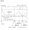
- the control unit 20 determines whether or not the temperature of the microchip 30 is lower than a preset lower limit value (lower-limit temperature: see FIG. 4 ), based on the signal from the temperature sensor 19, i.e.
- the control unit 20 causes the cooling unit to stop cooling or reduce output. This is because if the temperature within the channel 32 of the microchip 30 becomes too low, the viscosity of samples increases and electrophoresis becomes difficult . It is noted that the first set temperature is set as a temperature higher than the second set temperature.
- FIG. 2 is an exploded perspective view showing an example of the microchip used in Embodiment 1 of the present invention.
- the microchip 30 includes a substrate 31 a and a cover member 31 b that covers the substrate 31 a.
- the substrate 31 a and the cover member 31 b are both formed from a light transmissive material such as a transparent resin material or glass.
- the substrate 31 a includes a pair of recessed portions 34a and 34b and a groove 32a connecting these recessed portions.
- the cover member 31 b includes through holes 33a and 33b that are formed at positions aligned with respective openings of the recessed portions 34a and 34b of the substrate 31 a overlaid on the cover member 31 b.
- a portion formed by aligning the recessed portion 34a and the through hole 33a and a portion formed by aligning the recessed portion 34b and the through hole 33b serve as liquid reservoirs of the buffer solution, in which the electrodes 14a and 14b are disposed respectively.
- the position at which the light source 16 performs light irradiation and the position at which the light receiving element 17 receives transmitted light are both not particularly limited as long as they face the channel 32. It is, however, to be noted that in terms of irradiation efficiency, it is preferable for the cover member 31 b to have a recess in a portion that faces the light source 16. Furthermore, in terms of light receiving efficiency, it is also preferable for the substrate 31a to have a recess in a portion that faces the light receiving element 17.
- the main surface of the microchip 30 it is preferable for the main surface of the microchip 30 to have a film adhering thereto in advance in order to prevent dust or the like from entering these recesses before use.
- the film adhering to the cover member 31 b is preferably formed so as to at the same time cover the through holes 33a and 33b, in addition to the recesses.
- FIG. 3 is a flowchart showing the operation of the analysis apparatus according to Embodiment 1 of the present invention.
- FIG. 4 shows a change in the temperature of a microchip when the analysis apparatus according to Embodiment 1 of the present invention is operated. Note that FIGS. 1 and 2 are also appropriately referenced in the following description.
- an analysis method is implemented by operating the analysis apparatus 10. The description of the analysis method according to Embodiment 1 is substituted with the description of the operation of the analysis apparatus 10.
- the control unit 20 first causes the cooling unit to start cooling the microchip 30 (step S1). Specifically, the control unit 20 causes the driving circuit 13 to start supplying current to the electron cooling element 12. In this case, the value of current supplied to the electron cooling element 12 is set constant in order to keep the set temperature constant in the cooling unit. Through the execution of step S1, the temperature of the microchip 30 starts dropping gradually as shown in FIG. 4 .
- step S2 determines whether or not the temperature measured by the temperature sensor 19 is less than or equal to the set temperature (step S2). As a result of the determination in step S2, if the measured temperature is not less than or equal to the set temperature, the control unit 20 enters its standby state. On the other hand, if the result of the determination in step S2 indicates that the measured temperature is less than or equal to the set temperature, the control unit 20 executes step S3.
- step S3 when a sample is injected into the channel 32 of the microchip 30 by an operator, the control unit 20 causes the voltage application unit to start applying voltage and causes the optical analysis unit to start conducting optical analysis (step S3). Specifically, the control unit 20 causes the power supply circuit 15 to apply voltage between the electrodes 14a and 14b and further causes the light source 16 to perform light irradiation. This increases the temperature of the microchip 30, but the temperature will not exceed the upper-limit temperature because the cooling unit continues to cool the microchip.
- step S3 the light receiving element 17 outputs a signal in accordance with the amount of light received, and accordingly the analysis unit 18 measures the component quantity of a target component based on the output signal.
- the analysis unit 18 notifies the control unit 20 of that fact.
- the control unit 20 causes the voltage application unit to stop apply voltage and causes the optical analysis unit to stop conducting optical analysis.
- step S4 determines whether or not all measurements have ended. Specifically, in step S4, the control unit 20 determines whether or not an operator has input an instruction to end all measurements. As a result of the determination in step S4, if all measurements have not ended, the operator will inject a new sample into the microchip 30, upon which the control unit 20 executes step S3 again. On the other hand, if the result of the determination in step S4 indicates that all measurements have ended, the control unit 20 ends the processing.
- Embodiment 1 the microchip 30 is sufficiently cooled in advance prior to execution of electrophoresis, and electrophoresis is executed thereafter. Accordingly, Embodiment 1 enables the temperature of the microchip 30 to be optimized in electrophoresis using the microchip 30.
- Embodiment 2 has a similar configuration to the analysis apparatus 10 of Embodiment 1 shown in FIG. 1 , but it differs from the analysis apparatus of Embodiment 1 in the processing performed by the control unit. Note that the microchip 30 shown in FIGS. 1 and 2 is also used in Embodiment 2.
- FIG. 5 is a flowchart showing the operation of the analysis apparatus according to Embodiment 2 of the present invention.
- FIG. 6 shows a change in the temperature of the microchip when the analysis apparatus according to Embodiment 2 of the present invention is operated. Note that FIGS. 1 and 2 are also appropriately referenced in the following description.
- Step S11 is the same as step S1 shown in FIG. 3 .
- the relationship between the set temperature and the temperature of the microchip is, as shown in FIG. 6 , the same as in the case of FIG. 4 described in Embodiment 1.
- step S12 determines whether or not the temperature measured by the temperature sensor 19 is less than or equal to the set temperature. As a result of the determination in step S12, if the measured temperature is not less than or equal to the set temperature, the control unit 20 enters its standby state. On the other hand, if the result of the determination in step S12 indicates that the measured temperature is less than or equal to the set temperature, the control unit 20 executes step S13.
- step S13 the control unit 20 increases output of the cooling unit and thereby enhances cooling.
- the control unit 20 increases the value of current supplied from the driving circuit 13 to the electron cooling element 12.
- Step S14 is the same as step S3 shown in FIG. 3 .
- step S14 the light receiving element 17 outputs a signal in accordance with the amount of light received, and accordingly the analysis unit 18 measure the component quantity of a target component based on the output signal.
- the analysis unit 18 when the measurement has ended, the analysis unit 18 also notifies the control unit 20 of that fact.
- step S15 when receiving the notification from the analysis unit 18, the control unit 20 stops voltage application by the voltage application unit and optical analysis by the optical analysis unit, and at the same time, reduces output of the cooling unit (step S15). Execution of step S15 suppresses the occurrence of a situation in which the temperature of the microchip 30 becomes lower than the lower-limit temperature.
- step S16 determines whether or not all measurements have ended.
- Step S16 is the same as step S4 shown in FIG. 3 .
- the control unit 20 also determines whether or not an operator has input an instruction to end all measurements. As a result of the determination in step S16, if all measurements have not ended, the operator will inject a new sample into the microchip 30, upon which the control unit 20 executes step S13 again. On the other hand, if the result of the determination in step S16 indicates that all measurements have ended, the control unit 20 ends the processing.
- the control unit 20 increases the output of the cooling unit immediately before operating the voltage application unit and the optical analysis unit (immediately before step S14), and then reduces the output of the cooling unit after operations of the voltage application unit and the optical analysis unit have ended.
- Embodiment 2 it is possible to suppress a rise in the temperature of the microchip 30 more strongly than in Embodiment 1, as shown in FIG. 6 .
- the channel 32 there is a tendency for the channel 32 to have a shorter length and a higher heating value due to demand for downsizing of the microchip 30, and Embodiment 2 is in particular effective in such a case.
- FIG. 7 is a graph showing the upper surface temperature of the microchip, the channel temperature, and the temperature on the stage with the passage of time.
- the horizontal axis indicates time t
- the vertical axis indicates temperature T.
- State 4 and State 5 electrophoresis occurs within the channel 32 (see FIGS. 1 and 2 ) of the microchip 30.
- the adjustment of the output of the cooling unit needs to be performed based on the upper surface temperature of the microchip and the channel temperature. The following describes an analysis technique to be used at each temperature for each state.
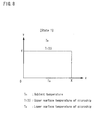
- FIG. 8 shows an example in which a microchip in State 1 is modeled.
- the microchip 30 is shown in a state as viewed from a widthwise side face (see FIG. 2 ).
- FIG. 9 shows an equation of state satisfied by a microchip in State 1.
- FIG. 9 also shows equations of state in the case where initial conditions and boundary conditions are given.
- ⁇ indicates the thermal conductivity of the microchip 30 (which is unique to the material), and ⁇ indicates the heat transfer coefficient from the surface of the microchip to the air (which depends on the material and the ambient conditions).
- the diameter (or width) of the channel 32 is extremely small as compared with the dimensions of the microchip 30 so that the channel 32 can be regarded as a point
- the thickness of the microchip 30 is so small that heat radiation from the side face of the microchip 30 can be ignored, and it is accordingly assumed that there is no temperature distribution in the x-axis direction (only the temperature distribution in the ⁇ -axis direction in FIG. 8 is taken into consideration).
- State 1 is a non-steady state.
- the temperature of the microchip 30 in State 1 can be simulated by applying an analytical technique such as a difference method or a finite-element method to the equations shown in FIG. 9 .
- the output of the cooling unit can be set to an appropriate value in State 1.
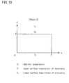
- FIG. 10 shows an example in which a microchip in State 2 is modeled.
- the microchip 30 is also shown in a state as viewed from a widthwise side face (see FIG. 2 ).
- FIG. 11 shows an equation of state satisfied by a microchip in State 2.
- FIG. 11 also shows equations of state in the case where boundary conditions are given.
- ⁇ similarly indicates the thermal conductivity of the microchip 30 (which is unique to the material), and ⁇ similarly indicates the heat transfer coefficient from the surface of the microchip to the air (which depends on the material and the ambient conditions).
- the diameter (or width) of the channel 32 is extremely small as compared with the dimensions of the microchip 30 so that the channel 32 can be regarded as a point
- the thickness of the microchip 30 is so small that heat radiation from the side face of the microchip 30 can be ignored, and it is accordingly assumed that there is no temperature distribution in the x-axis direction (only the temperature distribution in the y-axis direction in FIG. 10 is taken into consideration).
- State 2 is a steady state.
- the temperature of the microchip 30 in State 2 can be simulated by applying an analytical technique such as a difference method or a finite-element method to the equations shown in FIG. 11 .
- an analytical technique such as a difference method or a finite-element method
- the output of the cooling unit can be set to an appropriate value in State 2.
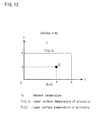
- FIG. 12 shows an example in which a microchip in State 3 and State 4 is modeled.
- the microchip 30 is also shown in a state as viewed from a widthwise side face (see FIG. 2 ).
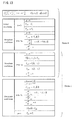
- FIG. 13 shows an equation of state satisfied by a microchip in State 3 or State 4.
- FIG. 13 also shows equations of state in the case where initial conditions and boundary conditions are given.
- ⁇ similarly indicates the thermal conductivity of the microchip 30 (which is unique to the material), and ⁇ similarly indicates the heat transfer coefficient from the surface of the microchip to the air (which depends on the material and the ambient conditions).
- the diameter (or width) of the channel 32 is extremely small as compared with the dimensions of the microchip 30 so that the channel 32 can be regarded as a point, and the thickness of the microchip 30 is so small that heat radiation from the side face of the microchip 30 can be ignored.
- heat is generated from the channel and therefore temperature distribution also occurs in the x-axis direction. For this reason, State 3 and State 4 can be considered to be two-dimensional non-steady states.
- the temperature of the microchip 30 in State 3 and State 4 can be simulated by applying an analytical technique such as a difference method or a finite-element method to the equations shown in FIG. 13 .
- an analytical technique such as a difference method or a finite-element method
- the output of the cooling unit can be set to an appropriate value in State 3 and State 4.
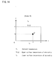
- FIG. 14 shows an example in which a microchip in State 5 is modeled.
- the microchip 30 is also shown in a state as viewed from a widthwise side face (see FIG. 2 ).
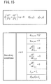
- FIG. 15 shows an equation of state satisfied by a microchip in State 5.
- FIG. 15 also shows equations of state in the case where boundary conditions are given.
- ⁇ similarly indicates the thermal conductivity of the microchip 30 (which is unique to the material).
- the diameter (or width) of the channel 32 is extremely small as compared with the dimensions of the microchip 30 so that the channel 32 can be regarded as a point, and the thickness of the microchip 30 is so small that heat radiation from the side face of the microchip 30 can be ignored.
- heat is generated from the channel, and therefore temperature distribution also occurs in the X-axis direction. For this reason, it can be thought that State 5 is a two-dimensional non-steady state.
- the temperature of the microchip 30 in State 5 can be simulated by applying an analytical technique such as a difference method or a finite-element method to the equations shown in FIG. 15 .
- an analytical technique such as a difference method or a finite-element method
- the output of the cooling unit can be set to an appropriate value in State 5.
- Embodiments 1 and 2 described above are not limited to the examples described above, and may be in any form including any of Modifications 1 to 3 described below.
- FIG. 16 shows the configuration of an analysis apparatus according to Modification 1.
- an analysis apparatus 40 according to Modification 1 further includes a stage 41 and an electron cooling element 42, in addition to the configuration of the analysis apparatus 10 shown in FIG. 1 .
- the driving circuit 13, the power supply circuit 15, the analysis unit 18, and the control unit 20 shown in FIG. 1 are not shown in FIG. 16 .
- control unit 20 causes the driving circuit 13 (see FIG. 1 ) to supply current to the electron cooling element 42 so as to cool the microchip 30 on the stage 41.
- control unit 20 enables voltage application and optical analysis to be executed while cooling the microchip 30.
- the control unit 20 instructs the driving circuit 13 (see FIG. 1 ) to supply current to the electron cooling element 12, instructs the power supply circuit 15 to apply voltage between the electrodes 14a and 14b, and instructs the light source 16 to perform light irradiation.
- the cooling of the microchip 30 prior to the start of measurement is performed on the stage 41, whereas the measurement and the cooling at the time of the measurement are performed on the stage 11.
- the microchip to be measured next can be cooled in advance, thus improving the efficiency of the measurement.
- FIGS. 17 show an example of the configuration of a microchip according to Modification 2, FIG. 17A being a plan view, FIG. 17B being a bottom view, and FIG. 17C being a side view.
- FIGS. 18 show another example of the configuration of the microchip according to Modification 2, FIG. 18A being a plan view, FIG. 18B being a bottom view, and FIG. 18C being a side view.
- FIGS. 19 show sill another example of the configuration of the microchip according to Modification 2, FIG. 19A being a plan view of a cover member and FIG. 19B being a plan view of a substrate.
- a microchip that has a superior heat radiation property than the microchip 30 shown in FIG. 2 is used as the microchip.
- a microchip 35 includes a substrate 31 a and a cover member 31 b that covers the substrate 31 a, and the microchip 35 also includes a heat radiation member 36.
- the heat radiation member 36 is formed from a material such as a metal material that has higher thermal conductivity than the material forming the main body portion (the substrate 31 a and the cover member 31 b) of the microchip.
- the heat radiation member 36 is formed such that the light irradiation from the light source 16 (see FIG. 1 ) to the channel 32 and the reception of transmitted light by the light receiving element 17 (see FIG. 1 ) are not inhibited.
- the heat radiation member 36 is formed so as to not shield the channel 32 on the main surface.
- the heat radiation member 36 is also formed so as to avoid the vicinity of the through holes 33a and 33b provided in the cover member 31 b, in order to avoid contact with the electrodes 14a and 14b (see FIG. 1 ).
- a microchip 37 also includes a heat radiation member 38 in addition to the substrate 31 a and the cover member 31 b that covers the substrate 31 a, as in the example shown in FIGS. 17A to 17C .
- the heat radiation member 38 has a plurality of fins 39 on the bottom surface side as shown in FIGS. 18B and 18C , and therefore has improved heat radiation capability.
- the microchip 37 shown in FIGS. 18A to 18C is useful in the case of using an air blowing apparatus as the cooling unit in place of the electron cooling element 12.
- a microchip 50 includes a substrate 51 a and a cover member 51 b that covers the substrate 51 a.
- the cover member 51 b is the same as the cover member 31 b shown in FIG. 2 , and is provided with through holes 53a and 53b.
- the substrate 51 a includes a groove 52 that forms a channel, and recessed portions 54a and 54b serving as liquid reservoirs, and in addition to these constituent elements, further includes an outer groove 55.
- the outer groove 55 is formed along the groove 52 and the recessed portions 54a and 54b so as to surround them.
- the upper surface of the outer groove 55 is blocked up.
- the outer groove 55 thus forms another channel like the groove 52.
- another channel is provided by the outer groove 55 so as to surround the vicinity of the other channel that is filled with the buffer solution.
- a cooling medium such as a liquid coolant
- a pump that supplies a cooling medium is used as the cooling unit, in place of the electron cooling element 12.
- FIG. 20 shows the configuration of an analysis apparatus according to Modification 3.
- the analysis apparatus 10 shown in FIG. 1 is disposed in a room 60 provided with an air circulation system.
- the air circulation system includes a dust-resistant filter 61, an antistatic blower 62, and a humidification filter 63 on the air intake side and includes an exhaust fan 64 on the air exhaust side.
- reference numerals 65 and 66 in FIG. 20 denote ducts.
- Modification 3 greatly reduces the contamination of dust or the like into the microchip 30. As a result, the accuracy of the measurement can be further improved.
- the temperature of the microchip can be optimized in electrophoresis using a microchip.
- the present invention is thus useful in an electrophoresis apparatus employing a microchip. While the invention has been particularly shown and described with reference to exemplary embodiments thereof, the invention is not limited to these embodiments. It will be understood by those of ordinary skill in the art that various changes in form and details may be made therein without departing from the spirit and scope of the present invention as defined by the claims.
Landscapes
- Life Sciences & Earth Sciences (AREA)
- Chemical & Material Sciences (AREA)
- Health & Medical Sciences (AREA)
- Molecular Biology (AREA)
- Electrochemistry (AREA)
- Chemical Kinetics & Catalysis (AREA)
- Physics & Mathematics (AREA)
- Analytical Chemistry (AREA)
- Biochemistry (AREA)
- General Health & Medical Sciences (AREA)
- General Physics & Mathematics (AREA)
- Immunology (AREA)
- Pathology (AREA)
- Environmental & Geological Engineering (AREA)
- Engineering & Computer Science (AREA)
- Dispersion Chemistry (AREA)
- Investigating, Analyzing Materials By Fluorescence Or Luminescence (AREA)
Applications Claiming Priority (2)
| Application Number | Priority Date | Filing Date | Title |
|---|---|---|---|
| JP2011064411 | 2011-03-23 | ||
| JP2012043555A JP5279926B2 (ja) | 2011-03-23 | 2012-02-29 | 分析装置、及び分析方法 |
Publications (2)
| Publication Number | Publication Date |
|---|---|
| EP2503328A1 true EP2503328A1 (fr) | 2012-09-26 |
| EP2503328B1 EP2503328B1 (fr) | 2022-12-28 |
Family
ID=46000705
Family Applications (1)
| Application Number | Title | Priority Date | Filing Date |
|---|---|---|---|
| EP12160935.8A Active EP2503328B1 (fr) | 2011-03-23 | 2012-03-23 | Appareil d'analyse et procédé d'analyse |
Country Status (4)
| Country | Link |
|---|---|
| US (1) | US8721859B2 (fr) |
| EP (1) | EP2503328B1 (fr) |
| JP (1) | JP5279926B2 (fr) |
| CN (1) | CN102692444B (fr) |
Families Citing this family (3)
| Publication number | Priority date | Publication date | Assignee | Title |
|---|---|---|---|---|
| CN103331099B (zh) * | 2013-06-28 | 2015-04-01 | 上海交通大学 | 自动散热型自由流电泳分离室装置 |
| EP3113863B1 (fr) * | 2014-02-24 | 2023-08-30 | Yourgene Health Canada Inc. | Système d'électrophorèse à socles modulaires |
| CN109477806A (zh) * | 2016-08-18 | 2019-03-15 | 深圳源光科技有限公司 | 具有集成光学感测器的电泳晶片 |
Citations (10)
| Publication number | Priority date | Publication date | Assignee | Title |
|---|---|---|---|---|
| WO1999012016A1 (fr) * | 1997-09-02 | 1999-03-11 | Caliper Technologies Corporation | Systeme microfluidique a regulation electrofluidique et electrothermique |
| JP2001099813A (ja) | 1999-09-29 | 2001-04-13 | Hitachi Ltd | キャピラリ電気泳動装置 |
| JP2003166976A (ja) | 2001-12-04 | 2003-06-13 | Hitachi High-Technologies Corp | マルチキャピラリー電気泳動装置 |
| WO2004059309A1 (fr) * | 2002-12-20 | 2004-07-15 | Northeastern University | Thermostat a commande de precision |
| US20060062696A1 (en) * | 2001-07-27 | 2006-03-23 | Caliper Life Sciences, Inc. | Optimized high throughput analytical systems |
| US20060210994A1 (en) * | 2005-03-15 | 2006-09-21 | Joyce Timothy H | Microfluidic systems and methods for using microfluidic devices |
| US20100108514A1 (en) * | 2007-03-30 | 2010-05-06 | Fujifilm Coporation | Method of controlling temperature |
| WO2010141921A1 (fr) * | 2009-06-05 | 2010-12-09 | Integenx Inc. | Système universel de préparation d'échantillons, et son utilisation dans un système d'analyse intégré |
| EP2418480A2 (fr) * | 2010-08-10 | 2012-02-15 | ARKRAY, Inc. | Appareil d'électrophorèse et son procédé de commande |
| EP2434272A1 (fr) * | 2010-09-27 | 2012-03-28 | Arkray, Inc. | Appareil d'analyse |
Family Cites Families (7)
| Publication number | Priority date | Publication date | Assignee | Title |
|---|---|---|---|---|
| JPH1010088A (ja) * | 1996-06-26 | 1998-01-16 | Hitachi Ltd | キャピラリ−電気泳動装置 |
| JP2000074880A (ja) * | 1998-08-28 | 2000-03-14 | Shimadzu Corp | マイクロチップのサンプル導入方法 |
| JP2001194338A (ja) * | 2000-01-12 | 2001-07-19 | Bunshi Biophotonics Kenkyusho:Kk | 蛍光検出電気泳動用冷却板および蛍光検出電気泳動装置 |
| US7090003B2 (en) * | 2001-10-19 | 2006-08-15 | Wisconsin Alumni Research Foundation | Method and apparatus for temperature control of a microfluidic device |
| WO2007063719A1 (fr) * | 2005-11-29 | 2007-06-07 | Nec Corporation | Puce electrophoretique, appareil electrophoretique et procede d'analyse d'echantillons |
| EP2363205A3 (fr) * | 2006-01-11 | 2014-06-04 | Raindance Technologies, Inc. | Dispositifs Microfluidiques Et Leurs Procédés D'utilisation Dans La Formation Et Le Contrôle De Nanoréacteurs |
| WO2009081722A1 (fr) * | 2007-12-21 | 2009-07-02 | Konica Minolta Medical & Graphic, Inc. | Micropuce et procédé d'envoi de liquide pour micropuce |
-
2012
- 2012-02-29 JP JP2012043555A patent/JP5279926B2/ja active Active
- 2012-03-22 US US13/427,037 patent/US8721859B2/en active Active
- 2012-03-23 CN CN201210080753.9A patent/CN102692444B/zh active Active
- 2012-03-23 EP EP12160935.8A patent/EP2503328B1/fr active Active
Patent Citations (10)
| Publication number | Priority date | Publication date | Assignee | Title |
|---|---|---|---|---|
| WO1999012016A1 (fr) * | 1997-09-02 | 1999-03-11 | Caliper Technologies Corporation | Systeme microfluidique a regulation electrofluidique et electrothermique |
| JP2001099813A (ja) | 1999-09-29 | 2001-04-13 | Hitachi Ltd | キャピラリ電気泳動装置 |
| US20060062696A1 (en) * | 2001-07-27 | 2006-03-23 | Caliper Life Sciences, Inc. | Optimized high throughput analytical systems |
| JP2003166976A (ja) | 2001-12-04 | 2003-06-13 | Hitachi High-Technologies Corp | マルチキャピラリー電気泳動装置 |
| WO2004059309A1 (fr) * | 2002-12-20 | 2004-07-15 | Northeastern University | Thermostat a commande de precision |
| US20060210994A1 (en) * | 2005-03-15 | 2006-09-21 | Joyce Timothy H | Microfluidic systems and methods for using microfluidic devices |
| US20100108514A1 (en) * | 2007-03-30 | 2010-05-06 | Fujifilm Coporation | Method of controlling temperature |
| WO2010141921A1 (fr) * | 2009-06-05 | 2010-12-09 | Integenx Inc. | Système universel de préparation d'échantillons, et son utilisation dans un système d'analyse intégré |
| EP2418480A2 (fr) * | 2010-08-10 | 2012-02-15 | ARKRAY, Inc. | Appareil d'électrophorèse et son procédé de commande |
| EP2434272A1 (fr) * | 2010-09-27 | 2012-03-28 | Arkray, Inc. | Appareil d'analyse |
Also Published As
| Publication number | Publication date |
|---|---|
| CN102692444A (zh) | 2012-09-26 |
| US20120241322A1 (en) | 2012-09-27 |
| US8721859B2 (en) | 2014-05-13 |
| JP5279926B2 (ja) | 2013-09-04 |
| JP2012211894A (ja) | 2012-11-01 |
| EP2503328B1 (fr) | 2022-12-28 |
| CN102692444B (zh) | 2015-10-28 |
Similar Documents
| Publication | Publication Date | Title |
|---|---|---|
| JP5802499B2 (ja) | 分析装置 | |
| US9086338B2 (en) | Sensing device | |
| JP3882484B2 (ja) | 電気泳動方法,電気泳動装置及びキャピラリアレイ | |
| JP4003374B2 (ja) | キャピラリアレイ電気泳動装置及び試料の分離・分析方法 | |
| EP2205358B1 (fr) | Aspiration et distribution de petits volumes de liquides | |
| JP5575043B2 (ja) | 分析装置 | |
| US7883613B2 (en) | Capillary electrophoresis apparatus | |
| JP2009042226A (ja) | キャピラリ電気泳動装置、及びサンプルトレイ | |
| EP2503328B1 (fr) | Appareil d'analyse et procédé d'analyse | |
| WO2017158811A1 (fr) | Appareil d'électrophorèse capillaire | |
| US7841247B2 (en) | Temperature controller for small fluid samples with different heat capacities | |
| CN110618223A (zh) | 具备样品调温功能的装置 | |
| US20240288491A1 (en) | Temperature control apparatus, test apparatus, temperature control method, and non-transitory computer readable medium | |
| KR20140075757A (ko) | 발열점 검출 방법 및 발열점 검출 장치 | |
| JP5928651B2 (ja) | 電気泳動用キャピラリユニット及びそのキャピラリユニットを備えた電気泳動装置 | |
| KR102007507B1 (ko) | 온도 제어 수단을 구비한 ir 분광 분석 셀 | |
| JP2010139491A (ja) | 反応液温度測定方法、反応液温度測定装置、反応液温度調整装置及び遺伝子の増幅反応処理を行うための装置 | |
| Fu et al. | Experimental and numerical investigation into the joule heating effect for electrokinetically driven microfluidic chips utilizing total internal reflection fluorescence microscopy | |
| Ono et al. | Single‐step CE for miniaturized and easy‐to‐use system | |
| JP4107313B2 (ja) | キャピラリアレイ電気泳動装置及び試料の分離・分析方法 | |
| US8815069B2 (en) | Disposable capillary electrophoresis detecting device | |
| US20100108514A1 (en) | Method of controlling temperature | |
| JP3791384B2 (ja) | 光分析用多連装セル | |
| Park et al. | Micro-Polymerase Chain Reaction Chip Reaction Chamber Temperature Measurement | |
| JP2005274421A (ja) | キャピラリ電気泳動装置及びキャピラリ電気泳動装置の排熱用ファン制御方法 |
Legal Events
| Date | Code | Title | Description |
|---|---|---|---|
| PUAI | Public reference made under article 153(3) epc to a published international application that has entered the european phase |
Free format text: ORIGINAL CODE: 0009012 |
|
| AK | Designated contracting states |
Kind code of ref document: A1 Designated state(s): AL AT BE BG CH CY CZ DE DK EE ES FI FR GB GR HR HU IE IS IT LI LT LU LV MC MK MT NL NO PL PT RO RS SE SI SK SM TR |
|
| AX | Request for extension of the european patent |
Extension state: BA ME |
|
| 17P | Request for examination filed |
Effective date: 20130326 |
|
| RAP1 | Party data changed (applicant data changed or rights of an application transferred) |
Owner name: ARKRAY, INC. |
|
| 17Q | First examination report despatched |
Effective date: 20160929 |
|
| STAA | Information on the status of an ep patent application or granted ep patent |
Free format text: STATUS: EXAMINATION IS IN PROGRESS |
|
| GRAP | Despatch of communication of intention to grant a patent |
Free format text: ORIGINAL CODE: EPIDOSNIGR1 |
|
| STAA | Information on the status of an ep patent application or granted ep patent |
Free format text: STATUS: GRANT OF PATENT IS INTENDED |
|
| INTG | Intention to grant announced |
Effective date: 20220921 |
|
| GRAS | Grant fee paid |
Free format text: ORIGINAL CODE: EPIDOSNIGR3 |
|
| GRAA | (expected) grant |
Free format text: ORIGINAL CODE: 0009210 |
|
| STAA | Information on the status of an ep patent application or granted ep patent |
Free format text: STATUS: THE PATENT HAS BEEN GRANTED |
|
| AK | Designated contracting states |
Kind code of ref document: B1 Designated state(s): AL AT BE BG CH CY CZ DE DK EE ES FI FR GB GR HR HU IE IS IT LI LT LU LV MC MK MT NL NO PL PT RO RS SE SI SK SM TR |
|
| REG | Reference to a national code |
Ref country code: GB Ref legal event code: FG4D |
|
| REG | Reference to a national code |
Ref country code: CH Ref legal event code: EP |
|
| REG | Reference to a national code |
Ref country code: DE Ref legal event code: R096 Ref document number: 602012079160 Country of ref document: DE |
|
| REG | Reference to a national code |
Ref country code: AT Ref legal event code: REF Ref document number: 1540801 Country of ref document: AT Kind code of ref document: T Effective date: 20230115 |
|
| REG | Reference to a national code |
Ref country code: IE Ref legal event code: FG4D |
|
| REG | Reference to a national code |
Ref country code: LT Ref legal event code: MG9D |
|
| PG25 | Lapsed in a contracting state [announced via postgrant information from national office to epo] |
Ref country code: SE Free format text: LAPSE BECAUSE OF FAILURE TO SUBMIT A TRANSLATION OF THE DESCRIPTION OR TO PAY THE FEE WITHIN THE PRESCRIBED TIME-LIMIT Effective date: 20221228 Ref country code: NO Free format text: LAPSE BECAUSE OF FAILURE TO SUBMIT A TRANSLATION OF THE DESCRIPTION OR TO PAY THE FEE WITHIN THE PRESCRIBED TIME-LIMIT Effective date: 20230328 Ref country code: LT Free format text: LAPSE BECAUSE OF FAILURE TO SUBMIT A TRANSLATION OF THE DESCRIPTION OR TO PAY THE FEE WITHIN THE PRESCRIBED TIME-LIMIT Effective date: 20221228 Ref country code: FI Free format text: LAPSE BECAUSE OF FAILURE TO SUBMIT A TRANSLATION OF THE DESCRIPTION OR TO PAY THE FEE WITHIN THE PRESCRIBED TIME-LIMIT Effective date: 20221228 |
|
| REG | Reference to a national code |
Ref country code: NL Ref legal event code: MP Effective date: 20221228 |
|
| REG | Reference to a national code |
Ref country code: AT Ref legal event code: MK05 Ref document number: 1540801 Country of ref document: AT Kind code of ref document: T Effective date: 20221228 |
|
| PG25 | Lapsed in a contracting state [announced via postgrant information from national office to epo] |
Ref country code: RS Free format text: LAPSE BECAUSE OF FAILURE TO SUBMIT A TRANSLATION OF THE DESCRIPTION OR TO PAY THE FEE WITHIN THE PRESCRIBED TIME-LIMIT Effective date: 20221228 Ref country code: LV Free format text: LAPSE BECAUSE OF FAILURE TO SUBMIT A TRANSLATION OF THE DESCRIPTION OR TO PAY THE FEE WITHIN THE PRESCRIBED TIME-LIMIT Effective date: 20221228 Ref country code: HR Free format text: LAPSE BECAUSE OF FAILURE TO SUBMIT A TRANSLATION OF THE DESCRIPTION OR TO PAY THE FEE WITHIN THE PRESCRIBED TIME-LIMIT Effective date: 20221228 Ref country code: GR Free format text: LAPSE BECAUSE OF FAILURE TO SUBMIT A TRANSLATION OF THE DESCRIPTION OR TO PAY THE FEE WITHIN THE PRESCRIBED TIME-LIMIT Effective date: 20230329 |
|
| PG25 | Lapsed in a contracting state [announced via postgrant information from national office to epo] |
Ref country code: NL Free format text: LAPSE BECAUSE OF FAILURE TO SUBMIT A TRANSLATION OF THE DESCRIPTION OR TO PAY THE FEE WITHIN THE PRESCRIBED TIME-LIMIT Effective date: 20221228 |
|
| PG25 | Lapsed in a contracting state [announced via postgrant information from national office to epo] |
Ref country code: SM Free format text: LAPSE BECAUSE OF FAILURE TO SUBMIT A TRANSLATION OF THE DESCRIPTION OR TO PAY THE FEE WITHIN THE PRESCRIBED TIME-LIMIT Effective date: 20221228 Ref country code: RO Free format text: LAPSE BECAUSE OF FAILURE TO SUBMIT A TRANSLATION OF THE DESCRIPTION OR TO PAY THE FEE WITHIN THE PRESCRIBED TIME-LIMIT Effective date: 20221228 Ref country code: PT Free format text: LAPSE BECAUSE OF FAILURE TO SUBMIT A TRANSLATION OF THE DESCRIPTION OR TO PAY THE FEE WITHIN THE PRESCRIBED TIME-LIMIT Effective date: 20230428 Ref country code: ES Free format text: LAPSE BECAUSE OF FAILURE TO SUBMIT A TRANSLATION OF THE DESCRIPTION OR TO PAY THE FEE WITHIN THE PRESCRIBED TIME-LIMIT Effective date: 20221228 Ref country code: EE Free format text: LAPSE BECAUSE OF FAILURE TO SUBMIT A TRANSLATION OF THE DESCRIPTION OR TO PAY THE FEE WITHIN THE PRESCRIBED TIME-LIMIT Effective date: 20221228 Ref country code: CZ Free format text: LAPSE BECAUSE OF FAILURE TO SUBMIT A TRANSLATION OF THE DESCRIPTION OR TO PAY THE FEE WITHIN THE PRESCRIBED TIME-LIMIT Effective date: 20221228 Ref country code: AT Free format text: LAPSE BECAUSE OF FAILURE TO SUBMIT A TRANSLATION OF THE DESCRIPTION OR TO PAY THE FEE WITHIN THE PRESCRIBED TIME-LIMIT Effective date: 20221228 |
|
| PG25 | Lapsed in a contracting state [announced via postgrant information from national office to epo] |
Ref country code: SK Free format text: LAPSE BECAUSE OF FAILURE TO SUBMIT A TRANSLATION OF THE DESCRIPTION OR TO PAY THE FEE WITHIN THE PRESCRIBED TIME-LIMIT Effective date: 20221228 Ref country code: PL Free format text: LAPSE BECAUSE OF FAILURE TO SUBMIT A TRANSLATION OF THE DESCRIPTION OR TO PAY THE FEE WITHIN THE PRESCRIBED TIME-LIMIT Effective date: 20221228 Ref country code: IS Free format text: LAPSE BECAUSE OF FAILURE TO SUBMIT A TRANSLATION OF THE DESCRIPTION OR TO PAY THE FEE WITHIN THE PRESCRIBED TIME-LIMIT Effective date: 20230428 Ref country code: AL Free format text: LAPSE BECAUSE OF FAILURE TO SUBMIT A TRANSLATION OF THE DESCRIPTION OR TO PAY THE FEE WITHIN THE PRESCRIBED TIME-LIMIT Effective date: 20221228 |
|
| REG | Reference to a national code |
Ref country code: DE Ref legal event code: R097 Ref document number: 602012079160 Country of ref document: DE |
|
| PG25 | Lapsed in a contracting state [announced via postgrant information from national office to epo] |
Ref country code: MC Free format text: LAPSE BECAUSE OF FAILURE TO SUBMIT A TRANSLATION OF THE DESCRIPTION OR TO PAY THE FEE WITHIN THE PRESCRIBED TIME-LIMIT Effective date: 20221228 Ref country code: DK Free format text: LAPSE BECAUSE OF FAILURE TO SUBMIT A TRANSLATION OF THE DESCRIPTION OR TO PAY THE FEE WITHIN THE PRESCRIBED TIME-LIMIT Effective date: 20221228 |
|
| REG | Reference to a national code |
Ref country code: CH Ref legal event code: PL |
|
| PLBE | No opposition filed within time limit |
Free format text: ORIGINAL CODE: 0009261 |
|
| STAA | Information on the status of an ep patent application or granted ep patent |
Free format text: STATUS: NO OPPOSITION FILED WITHIN TIME LIMIT |
|
| REG | Reference to a national code |
Ref country code: BE Ref legal event code: MM Effective date: 20230331 |
|
| 26N | No opposition filed |
Effective date: 20230929 |
|
| PG25 | Lapsed in a contracting state [announced via postgrant information from national office to epo] |
Ref country code: LU Free format text: LAPSE BECAUSE OF NON-PAYMENT OF DUE FEES Effective date: 20230323 |
|
| REG | Reference to a national code |
Ref country code: IE Ref legal event code: MM4A |
|
| PG25 | Lapsed in a contracting state [announced via postgrant information from national office to epo] |
Ref country code: SI Free format text: LAPSE BECAUSE OF FAILURE TO SUBMIT A TRANSLATION OF THE DESCRIPTION OR TO PAY THE FEE WITHIN THE PRESCRIBED TIME-LIMIT Effective date: 20221228 Ref country code: LI Free format text: LAPSE BECAUSE OF NON-PAYMENT OF DUE FEES Effective date: 20230331 Ref country code: IE Free format text: LAPSE BECAUSE OF NON-PAYMENT OF DUE FEES Effective date: 20230323 Ref country code: CH Free format text: LAPSE BECAUSE OF NON-PAYMENT OF DUE FEES Effective date: 20230331 |
|
| PG25 | Lapsed in a contracting state [announced via postgrant information from national office to epo] |
Ref country code: BE Free format text: LAPSE BECAUSE OF NON-PAYMENT OF DUE FEES Effective date: 20230331 |
|
| PG25 | Lapsed in a contracting state [announced via postgrant information from national office to epo] |
Ref country code: BG Free format text: LAPSE BECAUSE OF FAILURE TO SUBMIT A TRANSLATION OF THE DESCRIPTION OR TO PAY THE FEE WITHIN THE PRESCRIBED TIME-LIMIT Effective date: 20221228 |
|
| PG25 | Lapsed in a contracting state [announced via postgrant information from national office to epo] |
Ref country code: BG Free format text: LAPSE BECAUSE OF FAILURE TO SUBMIT A TRANSLATION OF THE DESCRIPTION OR TO PAY THE FEE WITHIN THE PRESCRIBED TIME-LIMIT Effective date: 20221228 |
|
| PGFP | Annual fee paid to national office [announced via postgrant information from national office to epo] |
Ref country code: DE Payment date: 20250319 Year of fee payment: 14 |
|
| PGFP | Annual fee paid to national office [announced via postgrant information from national office to epo] |
Ref country code: FR Payment date: 20250325 Year of fee payment: 14 |
|
| PGFP | Annual fee paid to national office [announced via postgrant information from national office to epo] |
Ref country code: GB Payment date: 20250321 Year of fee payment: 14 Ref country code: IT Payment date: 20250325 Year of fee payment: 14 |
|
| PG25 | Lapsed in a contracting state [announced via postgrant information from national office to epo] |
Ref country code: CY Free format text: LAPSE BECAUSE OF FAILURE TO SUBMIT A TRANSLATION OF THE DESCRIPTION OR TO PAY THE FEE WITHIN THE PRESCRIBED TIME-LIMIT; INVALID AB INITIO Effective date: 20120323 |
|
| PG25 | Lapsed in a contracting state [announced via postgrant information from national office to epo] |
Ref country code: HU Free format text: LAPSE BECAUSE OF FAILURE TO SUBMIT A TRANSLATION OF THE DESCRIPTION OR TO PAY THE FEE WITHIN THE PRESCRIBED TIME-LIMIT; INVALID AB INITIO Effective date: 20120323 |
|
| PG25 | Lapsed in a contracting state [announced via postgrant information from national office to epo] |
Ref country code: TR Free format text: LAPSE BECAUSE OF FAILURE TO SUBMIT A TRANSLATION OF THE DESCRIPTION OR TO PAY THE FEE WITHIN THE PRESCRIBED TIME-LIMIT Effective date: 20221228 |