EP2503849A2 - Diskrete Eingangssignalerzeugung über Ausgangskurzschlussschaltungserkennung - Google Patents
Diskrete Eingangssignalerzeugung über Ausgangskurzschlussschaltungserkennung Download PDFInfo
- Publication number
- EP2503849A2 EP2503849A2 EP12159624A EP12159624A EP2503849A2 EP 2503849 A2 EP2503849 A2 EP 2503849A2 EP 12159624 A EP12159624 A EP 12159624A EP 12159624 A EP12159624 A EP 12159624A EP 2503849 A2 EP2503849 A2 EP 2503849A2
- Authority
- EP
- European Patent Office
- Prior art keywords
- short
- circuit
- controller
- conditions
- condition
- Prior art date
- Legal status (The legal status is an assumption and is not a legal conclusion. Google has not performed a legal analysis and makes no representation as to the accuracy of the status listed.)
- Granted
Links
Images


Classifications
-
- H—ELECTRICITY
- H05—ELECTRIC TECHNIQUES NOT OTHERWISE PROVIDED FOR
- H05B—ELECTRIC HEATING; ELECTRIC LIGHT SOURCES NOT OTHERWISE PROVIDED FOR; CIRCUIT ARRANGEMENTS FOR ELECTRIC LIGHT SOURCES, IN GENERAL
- H05B47/00—Circuit arrangements for operating light sources in general, i.e. where the type of light source is not relevant
- H05B47/10—Controlling the light source
- H05B47/175—Controlling the light source by remote control
- H05B47/185—Controlling the light source by remote control via power line carrier transmission
-
- H—ELECTRICITY
- H05—ELECTRIC TECHNIQUES NOT OTHERWISE PROVIDED FOR
- H05B—ELECTRIC HEATING; ELECTRIC LIGHT SOURCES NOT OTHERWISE PROVIDED FOR; CIRCUIT ARRANGEMENTS FOR ELECTRIC LIGHT SOURCES, IN GENERAL
- H05B47/00—Circuit arrangements for operating light sources in general, i.e. where the type of light source is not relevant
- H05B47/20—Responsive to malfunctions or to light source life; for protection
- H05B47/25—Circuit arrangements for protecting against overcurrent
-
- Y—GENERAL TAGGING OF NEW TECHNOLOGICAL DEVELOPMENTS; GENERAL TAGGING OF CROSS-SECTIONAL TECHNOLOGIES SPANNING OVER SEVERAL SECTIONS OF THE IPC; TECHNICAL SUBJECTS COVERED BY FORMER USPC CROSS-REFERENCE ART COLLECTIONS [XRACs] AND DIGESTS
- Y02—TECHNOLOGIES OR APPLICATIONS FOR MITIGATION OR ADAPTATION AGAINST CLIMATE CHANGE
- Y02B—CLIMATE CHANGE MITIGATION TECHNOLOGIES RELATED TO BUILDINGS, e.g. HOUSING, HOUSE APPLIANCES OR RELATED END-USER APPLICATIONS
- Y02B20/00—Energy efficient lighting technologies, e.g. halogen lamps or gas discharge lamps
- Y02B20/30—Semiconductor lamps, e.g. solid state lamps [SSL] light emitting diodes [LED] or organic LED [OLED]
Definitions
- the present invention is related to driver circuits that supply power to output devices.
- Driver circuit is a generic term for a circuit tasked with supplying power to a load device.
- a driver circuit may include analog and/or digital circuitry for controlling the supply of power to the load device, and includes circuitry for detecting and protecting attached devices from short-circuit faults.
- a controller includes a driver circuit for supplying power to an output device.
- the driver circuit monitors the power supplied to detect short-circuit conditions at the output. Discrete inputs are generated by introducing intentional short-circuit conditions at the output of the driver circuit.
- the driver circuit detects short-circuit conditions at the output and interpretation logic distinguishes between short-circuit fault conditions and discrete inputs based on monitored characteristics of the detected short-circuit condition.
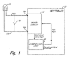
- Fig. 1 is a schematic diagram of a controller that includes a driver circuit connected to supply power to a load and to detect discrete inputs according to an embodiment of the present invention.
- Fig. 2 is a waveform that illustrates distinguishing characteristics between a short-circuit fault and a discrete input according to an embodiment of the present invention.
- Fig. 3 is a flowchart that illustrates a method of distinguishing between short-circuit faults and discrete inputs according to an embodiment of the present invention.
- Fig. 4 is a schematic diagram of a controller that includes a driver circuit connected to supply power to a load and to detect discrete inputs according to another embodiment of the present invention.
- a driver circuit controls the supply of power from an output of the driver circuit to a load device.
- the driver circuit is capable of detecting/receiving discrete input signals at the output of the driver circuit generated by the activation of one or more momentary switch devices. Activation of the one or more momentary switch devices creates a short-circuit condition at the output of the driver circuit that can be detected and distinguished by the driver circuit from short-circuit fault conditions.
- Fig. 1 is a schematic diagram of controller 10 that includes driver circuit 12 connected to supply power to load device 14 (also referred to as output device 14) from output terminals 16a, 16b and to detect discrete inputs at these terminals according to an embodiment of the present invention.
- Driver circuit 12 monitors the output supplied to output device 14 for short-circuit conditions, and provides a signal to interpretation logic 20 indicating whether a short-circuit condition is present.
- Interpretation logic 20 determines, based on characteristics of the short-circuit condition (e.g., duration, frequency, etc.), whether the short-circuit condition is a short-circuit fault condition or a discrete input generated by the activation of momentary switch 18.
- Momentary switch 18 creates an open-circuit between wires 22a and 22b when in an open or non-activated state, such that power flows in a circuit path from output terminals 16a and 16b to output device 14. However, momentary switch 18 creates a short-circuit path between wires 22a and 22b (and therefore between output terminals 16a and 16b) when closed or activated.
- Momentary switch 18 may be implemented using a number of well-known switching technologies, as long as the short-circuit connection provided by momentary switch 18 provides a characteristic short-circuit condition that can be distinguished from short-circuit fault conditions.
- momentary switch 18 may be implemented as an electromechanical switch, in which a user physically activates the switch by pressure or force, and wherein the switch maintains contact for a limited duration before returning to the inactive state.
- interpretation logic 20 identifies discrete inputs based on the (relatively) short duration of the short-circuit condition created by activation of the momentary switch 18.
- momentary switch is a solid-state device coupled with a sensor that detects a desired activation state and in response turns the solid-state device On to create a short-circuit condition between output terminals 16a and 16b.
- a short-circuit condition either due to a short-circuit fault condition in output device 14, a short-circuit fault between wires 22a and 22b, or an intentional short-circuit created by activating momentary switch 18, is detected by driver circuit 12.
- the characteristics of a short-circuit fault condition (associated with output device 14 or between wires 22a and 22b) is different than the characteristics of a short-circuit condition created by the activation of momentary switch 18.
- short-circuit fault conditions are typically non-transient events, in which the short-circuit condition persists for a period of time longer than the short-circuit condition resulting from the closing of momentary switch 18.
- interpretation logic 20 is able to distinguish between short-circuit fault conditions and discrete inputs provided by momentary switch 18.
- a benefit of the configuration described with respect to Fig. 1 is a discrete input is provided at output terminals 16a, 16b of controller 10 without requiring additional terminal connections and separate power supply requirements. This reduces the size and cost of controller 10.
- driver circuit 12 is responsible for the provision of power to output device 14 and monitoring of the provided current for overcurrent conditions.
- driver circuit 12 monitors the current at terminals 16a, 16b and compares the monitored current to a threshold value. If the monitored current exceeds the threshold value, then driver circuit 12 generates a short-circuit status signal that is provided to interpretation logic 20.
- Interpretation logic 20 includes logic for distinguishing between short-circuit fault conditions and discrete inputs provided via momentary switch 18 based on characteristics of the short-circuit condition monitored and reported by driver circuit 12.
- Interpretation logic 20 provides a fault signal output to driver circuit 12 that indicates whether a short-circuit fault condition is present, and a logic value output that indicates whether momentary switch 18 has been activated.
- the logic value output may be employed internally within controller 10, or may be communicated by controller 10 to an external controller (not shown) for processing.
- Interpretation logic 20, and the functions performed by interpretation logic 20 may be implemented with discrete analog and/or digital circuits, field programmable gate arrays (FPGAs), software executed on a microprocessor or machine, or combinations thereof.
- FPGAs field programmable gate arrays
- Fig. 2 is a waveform illustrating the difference between a short-circuit fault and a discrete input.
- the short-circuit status signal provided by driver circuit 12 to interpretation logic 20.
- the short-circuit status signal is high when driver circuit 12 has detected a short-circuit condition at output terminals 16a, 16b.
- the short-circuit status signal is low when no short-circuit condition has been detected by driver circuit 12.
- a first short-circuit condition is detected at time t1 and has a duration defined as t input .
- a second short-circuit condition is detected at time t2 and has a duration defined as t fault .
- the duration of the first short-circuit condition is less than the duration of the second short-circuit condition (i.e., t input ⁇ t fault ).
- the duration of the first short-circuit condition indicates that the condition is not a fault condition, but rather a discrete input generated by the temporary actuation of mentary switch 18.
- the duration of the second short-circuit waveform indicates that the second short-circuit condition is a short-circuit fault condition.
- Fig. 3 is a flowchart that illustrates a method 30 of distinguishing between short-circuit faults and discrete inputs according to an embodiment of the present invention. These steps are performed by interpretation logic 20 (shown in Fig. 1 ), and may be implemented by discrete circuitry, field-programmable gate arrays (FPGAs), or software executed by a processor/microprocessor.
- interpretation logic 20 shown in Fig. 1
- FPGAs field-programmable gate arrays
- step 32 The process begins at step 32.
- step 34 interpretation logic 20 checks the short-circuit status signal provided by driver circuit 12 (shown in Fig. 1 ).
- interpretation logic 20 determines whether the short-circuit status signal indicates a short-circuit condition. If the short-circuit status signal does not indicate a short-circuit condition, then the process returns to step 34 to check the short-circuit status signal. If the short-circuit status signal does indicate a short-circuit condition, then at step 38 interpretation logic 20 starts a timer (not shown).
- the timer value is compared to a short-circuit fault threshold time. If the timer value is greater than the short-circuit fault threshold time, this is indicative of a short-circuit fault condition (i.e., not a discrete input signal).
- interpretation logic 20 In response to the timer value being greater than the short-circuit fault threshold, then at step 42 interpretation logic 20 generates a short-circuit fault signal that is provided to driver circuit 12.
- driver circuit 12 in response to a detected short-circuit fault, driver circuit 12 will remove output power from output device 14 for a period of time, and then re-apply power.
- the process continues at step 34 to check the short-circuit status provided by driver circuit 12.
- step 40 If at step 40, the timer value is not greater than the short-circuit fault threshold then at step 44 interpretation logic 20 checks the short-circuit status signal provided by driver circuit 12. At step 46, interpretation logic 20 determines whether the short-circuit status signal is still indicating the presence of a short-circuit fault. If the short-circuit status signal indicates the short-circuit fault is still present, then the process returns to step 40, wherein the timer value is compared to the short-circuit fault threshold value. In this way, once the timer value exceeds the short-circuit fault threshold value, even if the short-circuit status signal still persists, a short-circuit fault condition is detected and appropriate signal is generated (at step 42).
- step 46 if the short-circuit status signal indicates that the short-circuit condition no longer persists, then at step 48 the timer is stopped.
- the timer value is compared to a discrete input threshold value. If the timer is greater than the discrete input threshold value then at step 52 a logic value is generated that indicates detection of a discrete input signal (i.e., activation of momentary switch 18).
- interpretation logic 20 detects a discrete input only when the timer value is less than the short-circuit fault threshold value and greater than the discrete input threshold value, although in other embodiments the algorithm employed may be modified, so long as a distinction can be made between characteristics of short-circuit fault conditions, and discrete input signals.
- Fig. 4 is a schematic diagram of a controller 60 that includes a driver circuit 62 connected to supply power to a load device 64 (also referred to as output device 64) and to detect discrete inputs according to another embodiment of the present invention. Similar to the embodiment described with respect to Fig. 1 , driver circuit 62 supplies power via output terminals 66a and 66b and wires 72a and 72b to load device 64.
- momentary switches 68 instead of a single momentary switch connected between output terminals 66a and 66b, a plurality of momentary switches 68-1, 68-2, ... 68n (collectively, momentary switches 68) connected in parallel between terminals 66a and 66b.
- each momentary switch is characterized by a different activation characteristic (e.g., each switch creates a short-circuit path that persists for a different duration of time).
- Driver circuit 62 provides power to output device 64 via terminals 66a and 66b and wires 72a and 72b, respectively.
- Driver circuit 62 detects short-circuit conditions.
- various methods may be employed to detect short-circuit conditions, such as by monitoring the output current provided to load device 64, monitoring the dissipation of thermal energy associated the supply of power to load device 64, monitoring impedance associated with the load (e.g., wherein a short-circuit is detected by a decrease in the monitored impedance) as well as other well-known methods.
- Driver circuit 62 creates a short-circuit status signal that is provided to interpretation logic 70, which uses characteristics of the detected short-circuit condition (e.g., frequency time duration) to distinguish between short-circuit fault conditions and discrete inputs provided by one of the plurality of momentary switches 68.
- characteristics of the detected short-circuit condition e.g., frequency time duration
- interpretation logic 70 includes logic for distinguishing between short-circuit fault conditions and discrete inputs provided via momentary switches 68 based on the duration of the short-circuit status signal provided by driver circuit 62.
- each of the plurality of momentary switches 68 has a unique activation period (i.e., creates a short-circuit condition between terminals 66a and 66b for a unique duration of time). The unique activation period of each momentary switch allows interpretation logic 70 to distinguish, not only between short-circuit fault conditions and discrete inputs, but between the plurality of discrete inputs provided via momentary switches 68.
- Interpretation logic 70 provides a fault signal output to driver circuit 62 that indicates whether a short-circuit fault condition is present, and one or more discrete logic value outputs that indicate which of the plurality of momentary switches 68 have been activated.
- the discrete logic values may be employed internally within controller 60, or may be communicate by controller 60 to an external controller (not shown) for processing.
- a driver circuit is able to take advantage of short-circuit detection/protection mechanisms commonly employed to monitor the output provided by the circuit to a particular load to convey discrete inputs to the circuit.
- the discrete input(s) is generated by a momentary switch connected at the output of the driver circuit that is capable of generating a temporary short-circuit at the output.
- Circuitry associated with the driver circuit distinguishes between characteristics of a short-circuit fault and the short-circuit condition created by activation of the momentary switch. In this way, discrete inputs are communicated to the output of the driver circuit without requiring additional pins or wiring.
Landscapes
- Testing Of Short-Circuits, Discontinuities, Leakage, Or Incorrect Line Connections (AREA)
- Emergency Protection Circuit Devices (AREA)
- Electronic Switches (AREA)
Applications Claiming Priority (1)
| Application Number | Priority Date | Filing Date | Title |
|---|---|---|---|
| US13/053,183 US8643982B2 (en) | 2011-03-21 | 2011-03-21 | Discrete input signal generation via output short-circuit detection |
Publications (3)
| Publication Number | Publication Date |
|---|---|
| EP2503849A2 true EP2503849A2 (de) | 2012-09-26 |
| EP2503849A3 EP2503849A3 (de) | 2013-07-17 |
| EP2503849B1 EP2503849B1 (de) | 2016-12-21 |
Family
ID=46027546
Family Applications (1)
| Application Number | Title | Priority Date | Filing Date |
|---|---|---|---|
| EP12159624.1A Active EP2503849B1 (de) | 2011-03-21 | 2012-03-15 | Diskrete Eingangssignalerzeugung über Ausgangskurzschlussschaltungserkennung |
Country Status (2)
| Country | Link |
|---|---|
| US (1) | US8643982B2 (de) |
| EP (1) | EP2503849B1 (de) |
Cited By (1)
| Publication number | Priority date | Publication date | Assignee | Title |
|---|---|---|---|---|
| CN114442715A (zh) * | 2021-12-29 | 2022-05-06 | 中国航空工业集团公司西安航空计算技术研究所 | 一种28v或开路的离散量输出电路 |
Families Citing this family (5)
| Publication number | Priority date | Publication date | Assignee | Title |
|---|---|---|---|---|
| JP5884067B2 (ja) * | 2010-09-15 | 2016-03-15 | パナソニックIpマネジメント株式会社 | 直流接続装置 |
| US9645948B2 (en) * | 2015-01-16 | 2017-05-09 | Hamilton Sundstrand Corporation | Access key generation for computer-readable memory |
| RU2585966C1 (ru) * | 2015-04-16 | 2016-06-10 | федеральное государственное бюджетное образовательное учреждение высшего образования "Иркутский национальный исследовательский технический университет" (ФГБОУ ВО "ИРНИТУ") | Способ определения величины и времени термического воздействия от тока короткого замыкания |
| DE112022004907T5 (de) * | 2021-12-14 | 2024-08-14 | Milwaukee Electric Tool Corporation | Kurzschlussminderung in einem elektrowerkzeug |
| CN115616968B (zh) * | 2022-12-16 | 2023-03-10 | 湖南高至科技有限公司 | 多通道激活控制装置 |
Family Cites Families (7)
| Publication number | Priority date | Publication date | Assignee | Title |
|---|---|---|---|---|
| JP3274377B2 (ja) * | 1996-12-25 | 2002-04-15 | 三菱電機株式会社 | 負荷短絡故障の検出方法及びその装置と電動パワーステアリング装置 |
| JP2005121433A (ja) * | 2003-10-15 | 2005-05-12 | Anden | 断線検出回路 |
| JP4218614B2 (ja) * | 2004-08-27 | 2009-02-04 | アイシン精機株式会社 | 座席状態検出装置、車両用ヘッドランプの照射方向調節装置及び着座検出装置 |
| DE602005012083D1 (de) | 2005-07-29 | 2009-02-12 | Osram Gmbh | Multizellen LED Anordnung, LED Array und Herstellungsverfahren |
| TWI270910B (en) | 2005-12-07 | 2007-01-11 | Inst Information Industry | Electronic switching device using non-interrupt voltage modulation switch |
| EP1879430A1 (de) | 2006-06-20 | 2008-01-16 | Zedel | Gesicherte elektrische Leuchte |
| SI2100368T1 (sl) * | 2006-12-08 | 2011-11-30 | Siemens Ag | Polprevodniški zaščitni elementi za obvladovanje kratkih stikov na strani enosmernega toka pri napetostnih pretvornikih v vmesnem krogu |
-
2011
- 2011-03-21 US US13/053,183 patent/US8643982B2/en active Active
-
2012
- 2012-03-15 EP EP12159624.1A patent/EP2503849B1/de active Active
Non-Patent Citations (1)
| Title |
|---|
| None |
Cited By (2)
| Publication number | Priority date | Publication date | Assignee | Title |
|---|---|---|---|---|
| CN114442715A (zh) * | 2021-12-29 | 2022-05-06 | 中国航空工业集团公司西安航空计算技术研究所 | 一种28v或开路的离散量输出电路 |
| CN114442715B (zh) * | 2021-12-29 | 2023-08-18 | 中国航空工业集团公司西安航空计算技术研究所 | 一种28v或开路的离散量输出电路 |
Also Published As
| Publication number | Publication date |
|---|---|
| EP2503849B1 (de) | 2016-12-21 |
| US8643982B2 (en) | 2014-02-04 |
| US20120243128A1 (en) | 2012-09-27 |
| EP2503849A3 (de) | 2013-07-17 |
Similar Documents
| Publication | Publication Date | Title |
|---|---|---|
| US8643982B2 (en) | Discrete input signal generation via output short-circuit detection | |
| EP1872452B1 (de) | Leistungsverteilungssystem unter verwendung von festkörperleistungsreglern | |
| US7619866B2 (en) | Electric trip device provided with monitoring means, circuit breaker comprising one such trip device and method of monitoring | |
| JP6523181B2 (ja) | 安全開閉装置およびその入力信号の検出方法 | |
| JP2018007551A (ja) | ソフトスタート及び保護を備える電源装置 | |
| US9859702B2 (en) | Interruption of a current | |
| KR102103594B1 (ko) | 소프트―스타트 및 보호를 구비한 전력 공급 장치 | |
| JP2013132157A (ja) | 太陽光発電システム | |
| EP1796238B1 (de) | Gleichstrom Lichtbogenfehler-Detektion und Schutz | |
| US9952286B2 (en) | Power-supply control device and programmable logic controller | |
| EP3391489B1 (de) | Erdschlussdetektions- und schutzschaltungssystem | |
| JP6919808B2 (ja) | 過電流抑制装置及び直流配電システム | |
| TWI502853B (zh) | 用於高電流脈衝電源供應器的短路控制 | |
| KR102053991B1 (ko) | 자가 진단이 가능한 워치독 모니터링 시스템 | |
| EP3627686B1 (de) | Motorantriebsvorrichtung | |
| CN107181235A (zh) | 用于高电流脉冲电源的短路控制 | |
| US8942811B2 (en) | Transcranial current stimulation device and method | |
| JP7723903B2 (ja) | 遮断制御装置 | |
| US10749330B2 (en) | Device and method for monitoring the activity of processing units in an electric trip switch | |
| US20210399569A1 (en) | Method for operating an electrical energy store | |
| EP3446391B1 (de) | Relaisschutzsystem | |
| CN111103842B (zh) | 自参数化的外围组件 | |
| WO2023228592A1 (ja) | バッテリ遮断システムおよび故障検出方法 | |
| HK1247293A1 (zh) | 具有软启动及保护功能的电源装置 | |
| WO2018220798A1 (ja) | モータ制御装置およびモータ制御方法 |
Legal Events
| Date | Code | Title | Description |
|---|---|---|---|
| PUAI | Public reference made under article 153(3) epc to a published international application that has entered the european phase |
Free format text: ORIGINAL CODE: 0009012 |
|
| AK | Designated contracting states |
Kind code of ref document: A2 Designated state(s): AL AT BE BG CH CY CZ DE DK EE ES FI FR GB GR HR HU IE IS IT LI LT LU LV MC MK MT NL NO PL PT RO RS SE SI SK SM TR |
|
| AX | Request for extension of the european patent |
Extension state: BA ME |
|
| PUAL | Search report despatched |
Free format text: ORIGINAL CODE: 0009013 |
|
| AK | Designated contracting states |
Kind code of ref document: A3 Designated state(s): AL AT BE BG CH CY CZ DE DK EE ES FI FR GB GR HR HU IE IS IT LI LT LU LV MC MK MT NL NO PL PT RO RS SE SI SK SM TR |
|
| AX | Request for extension of the european patent |
Extension state: BA ME |
|
| RIC1 | Information provided on ipc code assigned before grant |
Ipc: H05B 33/08 20060101AFI20130611BHEP |
|
| 17P | Request for examination filed |
Effective date: 20140113 |
|
| RBV | Designated contracting states (corrected) |
Designated state(s): AL AT BE BG CH CY CZ DE DK EE ES FI FR GB GR HR HU IE IS IT LI LT LU LV MC MK MT NL NO PL PT RO RS SE SI SK SM TR |
|
| REG | Reference to a national code |
Ref country code: DE Ref legal event code: R079 Ref document number: 602012026770 Country of ref document: DE Free format text: PREVIOUS MAIN CLASS: H05B0033080000 Ipc: H05B0037020000 |
|
| GRAP | Despatch of communication of intention to grant a patent |
Free format text: ORIGINAL CODE: EPIDOSNIGR1 |
|
| RIC1 | Information provided on ipc code assigned before grant |
Ipc: H05B 37/03 20060101ALI20160620BHEP Ipc: H05B 37/02 20060101AFI20160620BHEP Ipc: H05B 33/08 20060101ALI20160620BHEP |
|
| INTG | Intention to grant announced |
Effective date: 20160712 |
|
| GRAS | Grant fee paid |
Free format text: ORIGINAL CODE: EPIDOSNIGR3 |
|
| GRAA | (expected) grant |
Free format text: ORIGINAL CODE: 0009210 |
|
| AK | Designated contracting states |
Kind code of ref document: B1 Designated state(s): AL AT BE BG CH CY CZ DE DK EE ES FI FR GB GR HR HU IE IS IT LI LT LU LV MC MK MT NL NO PL PT RO RS SE SI SK SM TR |
|
| REG | Reference to a national code |
Ref country code: GB Ref legal event code: FG4D |
|
| REG | Reference to a national code |
Ref country code: CH Ref legal event code: EP |
|
| REG | Reference to a national code |
Ref country code: IE Ref legal event code: FG4D |
|
| REG | Reference to a national code |
Ref country code: AT Ref legal event code: REF Ref document number: 856481 Country of ref document: AT Kind code of ref document: T Effective date: 20170115 |
|
| REG | Reference to a national code |
Ref country code: DE Ref legal event code: R096 Ref document number: 602012026770 Country of ref document: DE |
|
| REG | Reference to a national code |
Ref country code: FR Ref legal event code: PLFP Year of fee payment: 6 |
|
| PG25 | Lapsed in a contracting state [announced via postgrant information from national office to epo] |
Ref country code: LV Free format text: LAPSE BECAUSE OF FAILURE TO SUBMIT A TRANSLATION OF THE DESCRIPTION OR TO PAY THE FEE WITHIN THE PRESCRIBED TIME-LIMIT Effective date: 20161221 |
|
| REG | Reference to a national code |
Ref country code: LT Ref legal event code: MG4D |
|
| REG | Reference to a national code |
Ref country code: NL Ref legal event code: MP Effective date: 20161221 |
|
| PG25 | Lapsed in a contracting state [announced via postgrant information from national office to epo] |
Ref country code: LT Free format text: LAPSE BECAUSE OF FAILURE TO SUBMIT A TRANSLATION OF THE DESCRIPTION OR TO PAY THE FEE WITHIN THE PRESCRIBED TIME-LIMIT Effective date: 20161221 Ref country code: SE Free format text: LAPSE BECAUSE OF FAILURE TO SUBMIT A TRANSLATION OF THE DESCRIPTION OR TO PAY THE FEE WITHIN THE PRESCRIBED TIME-LIMIT Effective date: 20161221 Ref country code: NO Free format text: LAPSE BECAUSE OF FAILURE TO SUBMIT A TRANSLATION OF THE DESCRIPTION OR TO PAY THE FEE WITHIN THE PRESCRIBED TIME-LIMIT Effective date: 20170321 Ref country code: GR Free format text: LAPSE BECAUSE OF FAILURE TO SUBMIT A TRANSLATION OF THE DESCRIPTION OR TO PAY THE FEE WITHIN THE PRESCRIBED TIME-LIMIT Effective date: 20170322 |
|
| REG | Reference to a national code |
Ref country code: AT Ref legal event code: MK05 Ref document number: 856481 Country of ref document: AT Kind code of ref document: T Effective date: 20161221 |
|
| PG25 | Lapsed in a contracting state [announced via postgrant information from national office to epo] |
Ref country code: RS Free format text: LAPSE BECAUSE OF FAILURE TO SUBMIT A TRANSLATION OF THE DESCRIPTION OR TO PAY THE FEE WITHIN THE PRESCRIBED TIME-LIMIT Effective date: 20161221 Ref country code: HR Free format text: LAPSE BECAUSE OF FAILURE TO SUBMIT A TRANSLATION OF THE DESCRIPTION OR TO PAY THE FEE WITHIN THE PRESCRIBED TIME-LIMIT Effective date: 20161221 Ref country code: FI Free format text: LAPSE BECAUSE OF FAILURE TO SUBMIT A TRANSLATION OF THE DESCRIPTION OR TO PAY THE FEE WITHIN THE PRESCRIBED TIME-LIMIT Effective date: 20161221 |
|
| PG25 | Lapsed in a contracting state [announced via postgrant information from national office to epo] |
Ref country code: NL Free format text: LAPSE BECAUSE OF FAILURE TO SUBMIT A TRANSLATION OF THE DESCRIPTION OR TO PAY THE FEE WITHIN THE PRESCRIBED TIME-LIMIT Effective date: 20161221 |
|
| PG25 | Lapsed in a contracting state [announced via postgrant information from national office to epo] |
Ref country code: IS Free format text: LAPSE BECAUSE OF FAILURE TO SUBMIT A TRANSLATION OF THE DESCRIPTION OR TO PAY THE FEE WITHIN THE PRESCRIBED TIME-LIMIT Effective date: 20170421 Ref country code: SK Free format text: LAPSE BECAUSE OF FAILURE TO SUBMIT A TRANSLATION OF THE DESCRIPTION OR TO PAY THE FEE WITHIN THE PRESCRIBED TIME-LIMIT Effective date: 20161221 Ref country code: CZ Free format text: LAPSE BECAUSE OF FAILURE TO SUBMIT A TRANSLATION OF THE DESCRIPTION OR TO PAY THE FEE WITHIN THE PRESCRIBED TIME-LIMIT Effective date: 20161221 Ref country code: EE Free format text: LAPSE BECAUSE OF FAILURE TO SUBMIT A TRANSLATION OF THE DESCRIPTION OR TO PAY THE FEE WITHIN THE PRESCRIBED TIME-LIMIT Effective date: 20161221 Ref country code: RO Free format text: LAPSE BECAUSE OF FAILURE TO SUBMIT A TRANSLATION OF THE DESCRIPTION OR TO PAY THE FEE WITHIN THE PRESCRIBED TIME-LIMIT Effective date: 20161221 |
|
| PG25 | Lapsed in a contracting state [announced via postgrant information from national office to epo] |
Ref country code: PT Free format text: LAPSE BECAUSE OF FAILURE TO SUBMIT A TRANSLATION OF THE DESCRIPTION OR TO PAY THE FEE WITHIN THE PRESCRIBED TIME-LIMIT Effective date: 20170421 Ref country code: AT Free format text: LAPSE BECAUSE OF FAILURE TO SUBMIT A TRANSLATION OF THE DESCRIPTION OR TO PAY THE FEE WITHIN THE PRESCRIBED TIME-LIMIT Effective date: 20161221 Ref country code: PL Free format text: LAPSE BECAUSE OF FAILURE TO SUBMIT A TRANSLATION OF THE DESCRIPTION OR TO PAY THE FEE WITHIN THE PRESCRIBED TIME-LIMIT Effective date: 20161221 Ref country code: IT Free format text: LAPSE BECAUSE OF FAILURE TO SUBMIT A TRANSLATION OF THE DESCRIPTION OR TO PAY THE FEE WITHIN THE PRESCRIBED TIME-LIMIT Effective date: 20161221 Ref country code: SM Free format text: LAPSE BECAUSE OF FAILURE TO SUBMIT A TRANSLATION OF THE DESCRIPTION OR TO PAY THE FEE WITHIN THE PRESCRIBED TIME-LIMIT Effective date: 20161221 Ref country code: ES Free format text: LAPSE BECAUSE OF FAILURE TO SUBMIT A TRANSLATION OF THE DESCRIPTION OR TO PAY THE FEE WITHIN THE PRESCRIBED TIME-LIMIT Effective date: 20161221 Ref country code: BE Free format text: LAPSE BECAUSE OF FAILURE TO SUBMIT A TRANSLATION OF THE DESCRIPTION OR TO PAY THE FEE WITHIN THE PRESCRIBED TIME-LIMIT Effective date: 20161221 Ref country code: BG Free format text: LAPSE BECAUSE OF FAILURE TO SUBMIT A TRANSLATION OF THE DESCRIPTION OR TO PAY THE FEE WITHIN THE PRESCRIBED TIME-LIMIT Effective date: 20170321 |
|
| REG | Reference to a national code |
Ref country code: DE Ref legal event code: R097 Ref document number: 602012026770 Country of ref document: DE |
|
| REG | Reference to a national code |
Ref country code: DE Ref legal event code: R119 Ref document number: 602012026770 Country of ref document: DE |
|
| PLBE | No opposition filed within time limit |
Free format text: ORIGINAL CODE: 0009261 |
|
| STAA | Information on the status of an ep patent application or granted ep patent |
Free format text: STATUS: NO OPPOSITION FILED WITHIN TIME LIMIT |
|
| REG | Reference to a national code |
Ref country code: CH Ref legal event code: PL |
|
| 26N | No opposition filed |
Effective date: 20170922 |
|
| PG25 | Lapsed in a contracting state [announced via postgrant information from national office to epo] |
Ref country code: DK Free format text: LAPSE BECAUSE OF FAILURE TO SUBMIT A TRANSLATION OF THE DESCRIPTION OR TO PAY THE FEE WITHIN THE PRESCRIBED TIME-LIMIT Effective date: 20161221 Ref country code: MC Free format text: LAPSE BECAUSE OF FAILURE TO SUBMIT A TRANSLATION OF THE DESCRIPTION OR TO PAY THE FEE WITHIN THE PRESCRIBED TIME-LIMIT Effective date: 20161221 |
|
| REG | Reference to a national code |
Ref country code: IE Ref legal event code: MM4A |
|
| PG25 | Lapsed in a contracting state [announced via postgrant information from national office to epo] |
Ref country code: LU Free format text: LAPSE BECAUSE OF NON-PAYMENT OF DUE FEES Effective date: 20170315 Ref country code: DE Free format text: LAPSE BECAUSE OF NON-PAYMENT OF DUE FEES Effective date: 20171003 |
|
| REG | Reference to a national code |
Ref country code: FR Ref legal event code: PLFP Year of fee payment: 7 |
|
| PG25 | Lapsed in a contracting state [announced via postgrant information from national office to epo] |
Ref country code: IE Free format text: LAPSE BECAUSE OF NON-PAYMENT OF DUE FEES Effective date: 20170315 Ref country code: LI Free format text: LAPSE BECAUSE OF NON-PAYMENT OF DUE FEES Effective date: 20170331 Ref country code: CH Free format text: LAPSE BECAUSE OF NON-PAYMENT OF DUE FEES Effective date: 20170331 Ref country code: SI Free format text: LAPSE BECAUSE OF FAILURE TO SUBMIT A TRANSLATION OF THE DESCRIPTION OR TO PAY THE FEE WITHIN THE PRESCRIBED TIME-LIMIT Effective date: 20161221 |
|
| PG25 | Lapsed in a contracting state [announced via postgrant information from national office to epo] |
Ref country code: MT Free format text: LAPSE BECAUSE OF NON-PAYMENT OF DUE FEES Effective date: 20170315 |
|
| PG25 | Lapsed in a contracting state [announced via postgrant information from national office to epo] |
Ref country code: HU Free format text: LAPSE BECAUSE OF FAILURE TO SUBMIT A TRANSLATION OF THE DESCRIPTION OR TO PAY THE FEE WITHIN THE PRESCRIBED TIME-LIMIT; INVALID AB INITIO Effective date: 20120315 |
|
| PG25 | Lapsed in a contracting state [announced via postgrant information from national office to epo] |
Ref country code: CY Free format text: LAPSE BECAUSE OF NON-PAYMENT OF DUE FEES Effective date: 20161221 |
|
| PG25 | Lapsed in a contracting state [announced via postgrant information from national office to epo] |
Ref country code: MK Free format text: LAPSE BECAUSE OF FAILURE TO SUBMIT A TRANSLATION OF THE DESCRIPTION OR TO PAY THE FEE WITHIN THE PRESCRIBED TIME-LIMIT Effective date: 20161221 |
|
| PG25 | Lapsed in a contracting state [announced via postgrant information from national office to epo] |
Ref country code: TR Free format text: LAPSE BECAUSE OF FAILURE TO SUBMIT A TRANSLATION OF THE DESCRIPTION OR TO PAY THE FEE WITHIN THE PRESCRIBED TIME-LIMIT Effective date: 20161221 |
|
| PG25 | Lapsed in a contracting state [announced via postgrant information from national office to epo] |
Ref country code: AL Free format text: LAPSE BECAUSE OF FAILURE TO SUBMIT A TRANSLATION OF THE DESCRIPTION OR TO PAY THE FEE WITHIN THE PRESCRIBED TIME-LIMIT Effective date: 20161221 |
|
| P01 | Opt-out of the competence of the unified patent court (upc) registered |
Effective date: 20230522 |
|
| PGFP | Annual fee paid to national office [announced via postgrant information from national office to epo] |
Ref country code: GB Payment date: 20260220 Year of fee payment: 15 |
|
| PGFP | Annual fee paid to national office [announced via postgrant information from national office to epo] |
Ref country code: FR Payment date: 20260219 Year of fee payment: 15 |