EP2504852B1 - Elektroschalter mit gleitelement zur herstellung eines kurzschlusses oder wahlschalters - Google Patents
Elektroschalter mit gleitelement zur herstellung eines kurzschlusses oder wahlschalters Download PDFInfo
- Publication number
- EP2504852B1 EP2504852B1 EP10799115.0A EP10799115A EP2504852B1 EP 2504852 B1 EP2504852 B1 EP 2504852B1 EP 10799115 A EP10799115 A EP 10799115A EP 2504852 B1 EP2504852 B1 EP 2504852B1
- Authority
- EP
- European Patent Office
- Prior art keywords
- conductive
- slide
- electrically
- pair
- primary
- Prior art date
- Legal status (The legal status is an assumption and is not a legal conclusion. Google has not performed a legal analysis and makes no representation as to the accuracy of the status listed.)
- Not-in-force
Links
Images

Classifications
-
- H—ELECTRICITY
- H01—ELECTRIC ELEMENTS
- H01H—ELECTRIC SWITCHES; RELAYS; SELECTORS; EMERGENCY PROTECTIVE DEVICES
- H01H15/00—Switches having rectilinearly-movable operating part or parts adapted for actuation in opposite directions, e.g. slide switch
- H01H15/02—Details
- H01H15/06—Movable parts; Contacts mounted thereon
-
- H—ELECTRICITY
- H01—ELECTRIC ELEMENTS
- H01H—ELECTRIC SWITCHES; RELAYS; SELECTORS; EMERGENCY PROTECTIVE DEVICES
- H01H39/00—Switching devices actuated by an explosion produced within the device and initiated by an electric current
- H01H39/006—Opening by severing a conductor
-
- H—ELECTRICITY
- H01—ELECTRIC ELEMENTS
- H01H—ELECTRIC SWITCHES; RELAYS; SELECTORS; EMERGENCY PROTECTIVE DEVICES
- H01H39/00—Switching devices actuated by an explosion produced within the device and initiated by an electric current
- H01H39/004—Closing switches
Definitions
- the present invention relates to an electrical switch.
- the invention relates to an electrical switch said "sliding drawer”, including an electrical switch of the type comprising a hollow body defining a cavity, an actuator formed in this cavity, a sliding drawer mounted in the cavity downstream of the actuator and having at least one conductive portion, and at least two primary electrical conductive pads installed in the thickness of the hollow body and opening laterally into the cavity, the conductive portion of the sliding drawer and the two primary electrical conductive pads being electrically connected between they when the sliding drawer is in a first position, thus closing a first electrical circuit, and the sliding drawer being adapted, under the effect of the operation of the actuator, to move from its first position to a second position in which at least one of said primary electrical conductive pads is no longer connected electrically to said conductive portion of the sliding drawer.
- an electrical switch of the type comprising a hollow body defining a cavity, an actuator formed in this cavity, a sliding drawer mounted in the cavity downstream of the actuator and having at least one conductive portion, and at least two primary electrical conductive pads installed in the thickness of the hollow body and opening laterally
- the electrical switch object of this disclosure can be used as a circuit breaker or as a switch, according to the embodiments. It is particularly suitable for electrical circuits with very high current.
- the document FR 2 788 165 discloses an example of an electrical switch of the aforementioned type, wherein electrical conductive pads passing through the thickness of the hollow body are clamped against the conductive portion of a slide mounted movably inside the hollow body, by screwing. This connection by screwing does not ensure sufficient reliability of the electrical contacts between the movable drawer and the conductive pads. Under the effect of external constraints (vibrations, shocks ...), the Screw connection can loosen, causing false contacts, arcing and other parasitic phenomena.
- WO 97/41582 describes an electrical switch according to the preamble of claims 1 and 2.
- An object of the present invention is to provide an electrical switch without the disadvantages mentioned above.
- an object of the present invention is to provide an electrical switch switch, can be assembled very simply, acting in a very short time, and providing reliable electrical connections.
- a switch of the aforementioned type comprising a hollow body delimiting a cavity, an actuator formed in said cavity, a sliding drawer mounted in said cavity downstream of said actuator and having at least one conductive portion, a first and a second electrical conductive pad forming a first pair, and a downstream electrical conductive pad disposed downstream of said first pair, wherein said electrical conductive pads are installed in the thickness of the hollow body and open laterally in the cavity, in which the conductive portion of the sliding drawer and the two electrical conductive pads of the first pair are electrically connected to each other when the sliding drawer is in a first position, thus closing a first electrical circuit, in which the sliding drawer is able to move from his first position to a second position under the effect of the operation of the actuator, wherein the conductive portion of the sliding spool comprises a first protuberance located upstream of the first electrical conductive pad of the first pair, and a second protuberance located upstream of the electrical conductive pad downstream, and wherein,
- Another object of the present invention is to provide an electrical switch that can be assembled very simply, acting in a very short time and providing reliable electrical connections.
- this objective is achieved by means of an electrical switch of the aforementioned type, in which the connection between the conductive portion of the sliding drawer and the two primary electrical conductive pads is a permanent electrical breakable joint constituted by a weld.
- this objective is also achieved by means of an electrical switch of the aforementioned type, in which the connection between the conductive portion of the sliding drawer and the two electrical conductive pads is a permanent electric breakable joint constituted by a solder.
- the switch has a circuit breaker function: When, under the effect of the actuator, the sliding drawer passes from its first to its second position, at least one of the pads is no longer electrically connected to the portion conductive sliding drawer. The electrical connection between the two primary electrical conductive pads is broken, and the first electrical circuit is open.
- solder like the solder, are inexpensive to achieve.
- Another object of the present invention is to provide an electrical switch that can be assembled very simply, and allowing a very fast breaking of the electrical connections and therefore actuation in a very short time.
- this objective is achieved by means of an electrical switch of the aforementioned type, in which the junction facet of at least one electrical conductive pad and the corresponding junction facet of the diverging conductive portion. downstream.
- each junction facet of each primary electrical conductive pad and the corresponding junction facet of the conductive portion diverges downstream.
- Such a configuration allows the sliding drawer to immediately disengage the primary electrical conductive pads, without parasitic friction, when it passes from its first to its second position. It ensures a reliable break of the first electrical circuit connecting the electrical conductive pads, and thus avoids arcing.
- primary electrical conductor pads means the electrical conductive pads which are connected to the conductive portion of the sliding drawer when it is in its first position, that is to say when the electric switch is in its initial state.
- the electrical switch according to the invention comprises a hollow body 12 delimiting an internal cavity 14 of circular section, closed at its lower end 14b by a bottom wall 15 and partially filled, in its upper part, with
- the cavity 14 may obviously have a rectangular cross section or any other suitable form.
- an axial direction is a direction parallel to the main axis X of the cavity 14 of the hollow body 12.
- a radial direction is a direction perpendicular to the main axis X of the cavity 14 and intersecting this axis.
- the adjectives and adverbs axial, radial, axially and radially are used with reference to the aforementioned axial and radial directions.
- an axial plane is a plane containing the main axis X of the cavity 14 and a radial plane is a plane perpendicular to this axis.
- an axial section is a section defined in an axial plane, and a radial section is a section defined in a radial plane.
- upstream and downstream terms are defined with respect to the direction of the X axis, which corresponds to the direction of movement, inside the cavity 14, of the sliding drawer 18 which will be defined in the following.
- the electrical switch comprises a pyrotechnic gas generator 16 (for example a micro gas generator and its pyrotechnic initiator or a pyrotechnic initiator according to the amount of gas to be supplied to operate the switch) which closes the cavity 14 at its level. upper end 14a.
- a pyrotechnic gas generator 16 for example a micro gas generator and its pyrotechnic initiator or a pyrotechnic initiator according to the amount of gas to be supplied to operate the switch
- the electric switch 10 is therefore single operation.
- electrical conductive pads are installed in the thickness of the hollow body and open laterally into the cavity 14. Each of these conductive pads comprises a junction facet directed towards the inside of the cavity 14.
- a sliding slide 18, comprising a conductive portion 19, is mounted in the cavity 14 downstream of the pyrotechnic gas generator 16.
- the conductive portion 19 of this slide 18 is initially connected to at least two primary electrical conductive pads closing a first electrical circuit .
- the slide 18 Upstream of its conductive portion 19, the slide 18 includes a non-conductive portion 24, at least one portion 24b has a section complementary to that of the cavity 14 and forms a piston adapted to slide inside the sleeve 13 according to the axial direction X.
- the conductive portion 19 is bonded to the non-conductive portion 24.
- the conductive portion 19 and the piston 24 are independent of one another.
- a gas expansion chamber 27 is provided between the pyrotechnic gas generator 16 and the piston 24.
- the piston 24 is provided, on its periphery, with at least one groove capable of receiving an O-ring seal 25, ensuring the seal between the gas expansion chamber 27 and the remainder of the cavity 14.
- a sealing means of the gas expansion chamber may for example be obtained by injecting, in an annular groove of the piston 24, a plastic material. more malleable than the one used to make the piston.
- a sealing means may also consist of a succession of baffles made on the piston 24, and serving to reduce the flow velocity of the leakage gases passing in the gap between the piston 24 and the inner wall of the cavity 14.
- a leakage orifice for the gases can be provided in the downstream part of the cavity 14, for example in its bottom wall 15.
- a hollow body 12 made of polymer reinforced by an injection process has sufficient mechanical strength.
- the hollow body 12 may be reinforced by a metal frame.
- the metal frame may surround the hollow body 12 to form a rigid protective shell.
- the metal armature can be directly inserted into the material at the time of injection.
- the pyrotechnic gas generator 16 and the electrical conductive pads must generally be mounted in insulated inserts.
- the electrical switch comprises, in the various embodiments presented, a pyrotechnic gas generator 16. It should be noted that this example is not limiting and any other device or actuator capable of exerting sufficient effort on the upper part of the sliding drawer 18 for breaking the connection between the electrical conductive pads and the drawer 18, may be used. As an example, it will be possible to use actuators with mechanical or electrical energy.
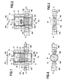
- the electrical switch 10 has a circuit breaker function for a first electrical circuit connecting two electrical conductive pads 20a, 20b opening into the cavity 14.
- the two electrical conductive pads 20a, 20b are arranged on the same radial axis AA, and each comprise a junction facet 26a, 26b, defined in a plane perpendicular to the axis AA and facing inwards of the cavity 14.
- the sliding drawer 18 comprises, in the example, a non-conductive portion (made of insulating material) provided with a first section 24b having a section complementary to that of the cavity 14 and forming a piston, and, downstream of this first section 24b, of a second section 24a of axial length L2.
- the sliding drawer Downstream of this non-conductive portion 24, the sliding drawer further comprises a conductive portion 19 which, in the example, has a length (taken along the axial direction X) substantially equal to the length L1 of the connecting facets 26a, 26b of the conductive pads 20a, 20b.
- junction facet 26a of the first electrical conductive pad 20a is connected to a corresponding junction facet 28a of the conductive portion 19 by a weld 22a, for example a tin-copper solder.
- junction facet 26b of the second primary electrical conductive pad 20b is connected to a corresponding junction facet 28b of the conductive portion 19 by a weld 22b, for example a tin-copper solder.
- the welds 22a, 22b can withstand external stresses such as vibration, shock, etc. and thus ensure reliable electrical contacts.
- the welds 22a, 22b are subjected to increasingly large shear forces.
- the forces due to the gas pressure exceed the shear strength forces of the welded connections 22a, 22b, the welds 22a, 22b break, releasing the sliding drawer 18 which then moves downstream, until abut against the bottom wall of the cavity 14.
- the path traveled by the sliding drawer 18 between its first and second positions is greater than the axial length L1 of the conductive portion 19.
- the connecting facets 28a, 28b and the whole of the conductive portion 19 are found downstream of the connecting facets 26a, 26b of the primary electrical conductor pads 20a, 20b.
- the joining facets 26a, 26b are then located facing the insulating portion 24 of the sliding drawer, so that the electrical connection between the pads 20a, 20b is broken and the first electrical circuit is open.
- the conductive portion 19 may extend upstream of the electrical conductive pads 20a, 20b.
- the conductive portion further has a recess upstream of each of the electrical conductive pads, whereby, after actuation of the pyrotechnic gas generator 16 and displacement of the slide 18, each primary electrical conductive pad 20a, 20b is found positioned opposite a recess, and the primary electrical circuit is open.
- the conductive portion 19 has a substantially parallelepiped shape. Its axial, rectangular section is represented on the figure 3 .
- the joining facets 28a, 28b of the conductive portion 19 of the sliding drawer 18 are planar, as are the corresponding facets 26a, 26b of the primary electrical conductive pads 20a, 20b.
- the conductive portion 19 may have a circular axial section, as illustrated in FIG. figure 4 .
- its connecting facets 28a, 28b have a convex shape and the corresponding connecting facets 26a, 26b of the electrical conductive pads 20a, 20b have a corresponding concave shape.
- the junction facets of the conductive portion 19 and the primary electrical conductive pads 20a, 20b are connected by a solder. All the characteristics, remarks, variants indicated above in connection with the first embodiment of the invention remain valid for this second embodiment and are therefore not repeated here.
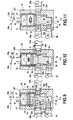
- the electrical switch 100 has a circuit breaker function for a first electrical circuit connecting two electrical conductive pads 20a, 20b opening into the cavity 14.
- two electrical conductive pads 20a, 20b protrude laterally inside the cavity 14. These pads are arranged along the same radial axis AA, and each comprise a junction facet 26a, 26b facing inwards of the cavity 14.
- a sliding drawer 18 is mounted directly downstream of the pyrotechnic gas generator 16.
- This drawer comprises, in the example, a non-conductive portion (made of insulating material) of complementary section to that of the cavity 14 and forming a piston, extended, downstream, by a conductive portion 19 of axial length L8 greater than the length L1 of the connecting facets of the electrical conductive pads 20a, 20b.
- the two electrical conductive pads 20a, 20b are electrically connected through the conductive portion 19, thereby closing an electrical circuit.
- the conductive portion 19 upstream of each of its junction facets, the conductive portion 19 further comprises a recess, 23a, 23b extending over an axial length L3.
- the length L3 is chosen greater than the length L1 of the conductive pads, and more generally so that, after actuation of the pyrotechnic gas generator 16 and movement of the slide 18, each electrical conductive pad 20a, 20b is found positioned opposite a recess 23a, 23b.
- the sliding drawer 18 disengages immediately from the two primary electrical conductor pads 20a, 20b , without parasitic friction, during its movement inside the cavity 14.
- the electrical connection between the two conductive pads is broken very reliably and a cut free of the electrical circuit is obtained.
- the breaking of the electrical connection between the primary electrical conductive pads 20a, 20b and the conductive portion 19, is obtained for a minimum path of the drawer 18 in the direction of sliding X.
- the entire portion of the sliding drawer 18 located upstream of the connecting facets 28a, 28b may be made of an insulating material.
- the sliding drawer 18 does not necessarily include recesses 23a, 23b upstream of the connecting facets 28a, 28b.
- an insulating strip is simply provided on each face of the sliding drawer 18 situated upstream of a junction facet 28a, 28b (for example, an insulating material fills the space formed by a recess 23a, 23b, see the Figures 15 and 16 ).
- junction facets 26a, 26b, 28a, 28b of the primary electrical conductive pads 20a, 20b and the sliding drawer 18 have, in radial section, a rectilinear section.
- these facets may however have non-rectilinear sections, if, in general, they diverge downstream.
- the junctions between the electrical conductive pads 20a, 20b and the conductive portion 19 may be constituted by any type of breakable permanent electrical connection.
- these junctions may be formed by solders, or welds.
- the primary electrical conductive pads 20a, 20b and the conductive portion 19 of the sliding drawer 18 can be made in one piece, but are delimited by breaking primers.
- the primary electrical conductive pads may be biased in contact with the conductive portion by resilient biasing means, for example a spring.
- the sliding drawer 18 advantageously comprises, upstream of each junction facet 28a, 28b of the conductive portion 19, an insulating portion 50a, 50b.
- the primary electrical conductor pads 20a, 20b biased towards the drawer slidable 18 by the springs 52a, 52b, come into contact with these insulating portions 50a, 50b.
- the electrical connection between the primary electrical conductor pads 20a, 20b is thus broken reliably despite the fact that these pads are biased towards the sliding drawer 18 by the springs 52a, 52b.
- a strip of insulating material 50a, 50b is simply attached to the sliding drawer 18 upstream of each junction facet 28a, 28b of the conductive portion 19.
- the sliding drawer 18 comprises a recess 23a, 23b upstream of each junction facet 28a, 28b and each recess 23a, 23b receives a strip of insulating material intended to come opposite an electrical conductive pad when the sliding drawer is located in his second position.
- the sliding drawer 18 may comprise a section of insulating material upstream of its conducting portion 19.
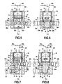
- the switch 200 here comprises a first and a second primary electrical conductive pad 20a, 20b forming a first pair, and a third electrical conductive pad 30 located downstream of the first pad pair (ie in a radial plane situated downstream of the plane in which are disposed the electrical conductive pads 20a, 20b of the first pair) and which will therefore be called "downstream conductive pad" in the following description.
- the electric switch 200 has a switch function. It is for example intended to isolate a faulty component connected to the second primary electrical conductive pad 20b by opening the first electrical circuit connecting the primary electrical conductor pads 20a, 20b and closing a second electrical circuit (bypass circuit) between the first primary electrical conductive pad 20a and the downstream electrical conductive pad 30.
- the switch comprises a sliding drawer 18 mounted in the cavity 14 downstream of the pyrotechnic gas generator 16.
- This sliding drawer 18 comprises a conductive portion 19 bonded, at its upper end, to an insulating portion 24 of complementary section to that of the cavity 14, and forming a piston.
- the switch 200 When the switch 200 is in its initial position (ie its first position), the two primary electrical conductor pads 20a, 20b are electrically connected via the conductive portion 19 of the sliding drawer 18, so as to close a first electrical circuit.
- junction facet 26a of the first electrical conductive pad is connected to the corresponding junction facet 28a of the conductive portion 19 by a weld 22a.
- junction facet 26b of the second electrical conductive pad is connected to the corresponding junction facet 28b of the conductive portion 19 by a weld 22b.
- first and the second primary electrical conductive pad 20a, 20b can be connected to the conductive portion 19 by any permanent electrical breakable junction.
- this junction can be a solder.
- the primary electrical conductive pads 20a, 20b and the conductive portion 19 of the sliding drawer can be made in one piece being delimited by breaking primers.
- the primary electrical conductive pads may be biased in contact with the conductive portion by resilient biasing means, for example a spring.
- the conductive portion 19 comprises a first protuberance in the form of a ramp 34 upstream of its junction facet 28a located opposite the first primary electrical conductive pad 20a.
- the lateral face portion of the conductive portion 19 which is located directly upstream of the facet of junction 28a, diverges upstream along a length L4, taken in the axial direction X.
- the length L4 is chosen substantially equal to the length L1 of the junction facets of the primary electrical conductive pads, also taken in the axial direction X.
- the conductive portion 19 also has a second protuberance in the form of a ramp 38 formed downstream of the connecting facets 28a, 28b. As shown in figure 7 when the sliding drawer 18 is in its first position, this second protrusion 38 is placed directly upstream of the downstream electrical conductive pad 30.
- the length L5 of this ramp 38 (taken in the axial direction X) is substantially equal to that L6 the junction facet 31 of the downstream electrical conductive pad 30 (taken in the axial direction X).
- the conductive portion 19 further comprises a recess 36 provided upstream of its junction facet 28b located opposite the second primary electrical conductive pad 20b.
- the first protrusion 34 is located upstream of the first primary electrical conductive pad 20a
- the recess 36 is located upstream of the second primary electrical conductive pad 20b
- the second protuberance 38 is located upstream of the downstream electrical conductive pad 30.
- the sliding drawer 18 is not in contact with the downstream electrical conductive pad 30, which remains inactive.
- the sliding drawer 18 moves downstream in the direction X, the first and the second protuberance 34, 38 are gradually tightened on the first primary electrical conductive pad 20a and on the downstream electrical conductor pad 30.
- the recess 36 is placed opposite the junction facet 26b of the second electrical conductive pad 20b.
- the electrical conductive pads 20a, 20b are no longer electrically connected and the first electrical circuit is open.
- the tightening of the protuberances 34, 38 on the electrical conductive pads 20a and 30 allows the conductive portion 19 to electrically connect these two pads 20a, 30 and thus to close a second electrical circuit (branch circuit).
- the cavity 14 is terminated in its downstream portion by a guide portion 32, the shape of which is complementary to that of the lower part of the sliding drawer 18.
- the guide portion 32 guides the sliding drawer 18 when it is moves from its first position to its second position. In particular, it prevents the sliding drawer 18 from moving away from the first primary electrical conductive pad 20a and the downstream electrical conductive pad 30, and thus increases the reliability of the electrical contacts in the second electrical circuit (bypass circuit), when the drawer sliding is in its second position.
- the sliding drawer ends, at its lower end, by a conical portion, intended to come into a conical conical recess provided in the bottom wall 15 of the hollow body 12.
- the protuberances 34 and 38 of the conductive portion 19 are located directly upstream of the connecting facets 28a, 28b.
- these protuberances it will obviously be possible for these protuberances to be situated upstream of these joining facets but at a distance from them. In this case, the path traveled by the sliding drawer between its first and second position will simply be larger. However, it must be ensured that the distances between the protuberances and the connecting facets with which they must respectively cooperate remain substantially indicated.
- the conductive portion 19 comprises, in the example considered, a recess 36 located upstream of the second primary electrical conductive pad 20b when the sliding drawer 18 is in its first position.
- This recess makes it possible to break the electrical contact between the sliding drawer and the second conductive pad 20b when the drawer makes its way inside the cavity.
- the sliding drawer may comprise an insulating portion, upstream of the joining facet 28b. This insulating portion is then configured to come opposite the second primary electrical conductive pad 20b once the sliding drawer 18 in its second position.
- the face of the sliding drawer located opposite the second primary electrical conductive pad 20b can diverger downstream, as well as the corresponding junction facet of the conductive pad 20b, whereby the sliding drawer 18 is able to disengage immediately from the electrical conductive pad 20b without parasitic friction.
- the downstream electrical conductive pad may be biased towards the inside of the cavity 14 by resilient biasing means, for example a spring.
- resilient biasing means for example a spring.
- the ramp 38 gradually constrains the downstream electrical conductive pad in a direction opposite to the force of said resilient biasing means.
- the downstream electrical conductive pad is biased in contact with the conductive portion 19 by said resilient biasing means.
- FIGS 9 to 11 illustrate an electric switch 201 according to a variant of the fourth embodiment according to the invention. All the characteristics previously described in connection with the Figures 7 and 8 remain valid and are therefore not described again.
- the conductive portion 19 of the sliding drawer 18 has a third protuberance 40, located in the vicinity of the recess 36.
- this protrusion 40 is positioned downstream of the recess 36 and upstream of the junction facet 28b of the conductive portion 19 connected to the second primary electrical conductive pad 20b.
- This protrusion 40 has an axial length L7 smaller than those L4, L5 of the first and the second protuberance 34, 38.
- the figure 10 shows the sliding drawer 18 in an intermediate position between its first and second position.
- the first and second protuberances 34, 38 began to tighten respectively on the first electrical conductive pad 20a and the downstream electrical conductive pad 30.
- the third protuberance 40 is clamped on the second electrical conductive pad 20b. Furthermore, the sliding drawer 18 is engaged in the guide portion 32.
- the three electrical conductive pads 20a, 20b and 30 are therefore short-circuited and the flow of current in the second circuit electrical (branch circuit) connecting the electrical conductor pads 20a and 30 begins before the first electrical circuit (which connects the electrical conductive pads 20a and 20b) is cut.
- the third protuberance 40 is located downstream of the second primary electrical conductive pad 20b, and the recess 36 is positioned opposite this second electrical conductive pad 20b.
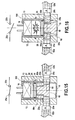
- FIGS. 12 to 14 illustrate an electrical switch 202 according to another variant of the fourth embodiment of the present invention, comprising a plurality of circuits initially mounted in parallel.
- the switch 202 comprises a first pair of primary electrical conductive pads 20a, 20b, and a second pair of primary electrical conductive pads 20c, 20d located downstream of said first pair 20a, 20b.
- the electrical conductive pads of the first pair are defined along an axis AA perpendicular to the axial direction X
- the electrical conductive pads of the second pair 20c, 20d are located along an axis BB parallel to axis AA, downstream of it.
- the sliding drawer 18 comprises a first conductive portion 42, substantially identical to that described in connection with the fifth embodiment described above, and a second conductive portion 44 located downstream of the first conductive portion 42.
- the two conductive portions 42 and 44 are separated from each other by an insulator 46 extending, in the example, in a radial plane.
- a connecting face 28a of the first conductive portion 42 is connected to a first primary electrical conductive pad 20a of the first pair 20a, 20b, and a second connecting facet 28b is connected. to the second primary electrical conductor pad 20b of the first pair 20a, 20b.
- the electrical conductive pads of the first pair 20a, 20b are connected to the first conductive portion 42 by welds 22a, 22b.
- the first conductive portion 42 of the sliding drawer 18 comprises a first protrusion 34 upstream of its junction facet 28a, and a second protrusion 38 located upstream of the first primary electrical conductive pad 20c of the second pair 20c, 20d.
- protuberances have a function identical to those described above in connection with the Figures 7 and 8 .
- the second conductive portion 44 is located opposite the electrical conductive pads 20c, 20d of the second pair.
- it comprises a first junction facet 28c connected by a weld 22c to the corresponding junction facet of the stud 20c, and a second junction facet connected by a weld 22d to the corresponding junction facet of the stud 20d.
- the connections between the electrical conductive pads and the conductive portions of the sliding drawer may be any other type of permanent electric breakable joint.
- these bonds may be solders.
- the electrical conductive pads and the conductive portions of the sliding drawer can be made in one piece, and be delimited by breaking primers.
- the primary electrical conductive pads may be biased in contact with the conductive portion by resilient biasing means, for example a spring.
- the sliding drawer 18 has a first recess 36 upstream of its junction facet 28b connected to the second conductive pad 20b of the first pair, and a second recess 48 upstream of its facet of junction 28d connected to the second electrical conductive pad 20d of the second pair.
- the primary electrical conductor pads 20a, 20b of the first pair are electrically connected via the first conductive portion 42 of the sliding drawer 18 and the primary electrical conductive pads 20c, 20d of the second pair are electrically connected via the second conductive portion 44 of the sliding drawer 18.
- the insulator 46 is placed upstream of the connecting facets 28c, 28d of the sliding drawer 18 connected to the second pair of primary electrical conductive pads 20c, 20d, and downstream of the second protrusion 38 and the second recess 48.
- first recess 36 is positioned opposite the junction facet 26b of the second primary electrical conductive pad of the first pair 20a, 20b.
- second recess 48 is positioned opposite the junction facet 26d of the second primary electrical conductive pad 20d of the second pair 20c, 20d.
- the insulator 46 is found downstream of the first primary electrical conductive pad 20c of the second pair.
- a bypass circuit is closed between the first electrical conductive pad 20a of the first pair and the first electrical conductive pad 20c of the second pair, via the first conductive portion 42 of the sliding drawer.
- the sliding drawer further comprises a third protuberance 40, shorter than the first and second protuberances 34, 38, located upstream of its junction facet 28b, and downstream of the recess 36.
- the sliding drawer By moving from its first to its second position under the effect of the actuation of the pyrotechnic gas generator 16, the sliding drawer passes through an intermediate position illustrated on the figure 13 .
- the first and second protuberances 34, 38 began to tighten respectively on the first primary electrical conductive pad 20a of the first pair and the first electrical conductive pad 20c of the second pair.
- the second electrical pad of the second pair is no longer in contact with the second conductive portion 44.
- the third protrusion 40 has clamped on the second primary electrical conductive pad 20b.
- the three electrical conductive pads 20a, 20b and 20c are short-circuited thanks to the third protrusion 40 and the passage of the current in the second electrical circuit (branch circuit) connecting the electrical conductive pads 20a and 20c begins before the first electrical circuit (which connects the primary electrical conductor pads 20a and 20b) is cut.
Landscapes
- Push-Button Switches (AREA)
- Slide Switches (AREA)
- Switch Cases, Indication, And Locking (AREA)
- Fuses (AREA)
- Air Bags (AREA)
- Switches Operated By Changes In Physical Conditions (AREA)
Claims (17)
- Elektroschalter (10), umfassend:- einen Hohlkörper (12), der einen Hohlraum (14) begrenzt,- ein Betätigungselement (16), das in dem Hohlraum (14) aufgenommen ist,- ein Gleitelement (18), das in dem Hohlraum (14) stromabwärts zum Betätigungselement (16) montiert ist und mindestens einen leitenden Abschnitt (19) umfasst, und- mindestens zwei primäre elektrisch leitende Kontaktstücke (20a, 20b), die in der Dicke des Hohlkörpers (12) installiert sind und seitlich in den Hohlraum (14) münden,wobei der leitende Abschnitt (19) des Gleitelements (18) und die beiden primären elektrisch leitenden Kontaktstücke (20a, 20b) elektrisch miteinander verbunden sind, wenn sich das Gleitelement (18) in einer ersten Position befindet, wodurch eine erste elektrische Schaltung geschlossen wird, und wobei unter der Wirkung der Funktion des Betätigungselements (16) das Gleitelement (18) geeignet ist, von seiner ersten Position in eine zweite Position überzugehen, in der mindestens eines der primären elektrisch leitenden Kontaktstücke (20a, 20b) elektrisch nicht mehr mit dem leitenden Abschnitt (19) des Gleitelements (18) verbunden ist,
wobei der Elektroschalter (10) dadurch gekennzeichnet ist, dass die Verbindung (22a, 22b) zwischen dem leitenden Abschnitt (19) des Gleitelements (18) und den beiden primären elektrisch leitenden Kontaktstücken (20a, 20b) eine permanente zerbrechbare elektrische Verbindung ist, die von einer Schweißnaht gebildet ist. - Elektroschalter (10), umfassend:- einen Hohlkörper (12), der einen Hohlraum (14) begrenzt,- ein Betätigungselement (16), das in dem Hohlraum (14) ausgenommen ist,- ein Gleitelement (18), das in dem Hohlraum (14) stromabwärts zum Betätigungselement (16) montiert ist und mindestens einen leitenden Abschnitt (19) umfasst, und- mindestens zwei primäre elektrisch leitende Kontaktstücke (20a, 20b), die in der Dicke des Hohlkörpers (12) installiert sind und seitlich in den Hohlraum (14) münden,wobei der leitende Abschnitt (19) des Gleitelements (18) und die beiden primären elektrisch leitenden Kontaktstücke (20a, 20b) elektrisch miteinander verbunden sind, wenn sich das Gleitelement (18) in einer ersten Position befindet, wodurch eine erste elektrische Schaltung geschlossen wird, und wobei unter der Wirkung der Funktion des Betätigungselements (16) das Gleitelement (18) geeignet ist, von seiner ersten Position in eine zweite Position überzugehen, in der mindestens eines der primären elektrisch leitenden Kontaktstücke (20a, 20b) elektrisch nicht mehr mit dem leitenden Abschnitt (19) des Gleitelements (18) verbunden ist,
wobei der Elektroschalter (10) dadurch gekennzeichnet ist, dass die Verbindung (22a, 22b) zwischen dem leitenden Abschnitt (19) des Gleitelements (18) und den beiden primären elektrisch leitenden Kontaktstücken (20a, 20b) eine permanente zerbrechbare elektrische Verbindung ist, die von einer Lötstelle gebildet ist. - Elektroschalter nach Anspruch 1 oder 2, bei dem die primären elektrisch leitenden Kontaktstücke einander gegenüberliegend entlang einer Achse senkrecht auf die Gleitrichtung (X) des Gleitelements angeordnet sind.
- Elektroschalter nach einem der Ansprüche 1 bis 3, bei dem das Betätigungselement (16) ein pyrotechnischer Gasgenerator ist, und das Gleitelement (18) einen Kolben (24) bildet oder mit einem solchen verbunden ist, der im Inneren des Hohlraums (14) beweglich ist, wobei eine Expansionskammer (27) zwischen dem Betätigungselement (16) und dem Kolben (24) definiert ist.
- Elektroschalter nach einem der Ansprüche 1 bis 4, bei dem die Verbindungsfacette (26a, 26b) mindestens eines primären elektrisch leitenden Kontaktstücks (20a, 20b) und die entsprechende Verbindungsfacette (28a, 28b) des leitenden Abschnitts (19) stromabwärts divergierend sind.
- Elektroschalter nach einem der Ansprüche 1 bis 5, bei dem das Gleitelement (18) einen Absatz (23a, 23b) stromaufwärts zu mindestens einer Verbindungsfacette (26a, 26b) des leitenden Abschnitts (19) umfasst.
- Elektroschalter nach einem der Ansprüche 1 bis 6, bei dem das Gleitelement (18) einen Isolierabschnitt stromaufwärts zu mindestens einer Verbindungsfacette (26a, 26b) des leitenden Abschnitts (19) umfasst.
- Elektroschalter nach einem der Ansprüche 1 bis 7, bei dem der Hohlraum (14) in seinem stromabwärtigen Teil durch einen Führungsabschnitt (32) beendet ist, der dazu bestimmt ist, das Gleitelement (18) zu führen, wenn dieses von seiner ersten in seine zweite Position übergeht.
- Elektroschalter nach einem der Ansprüche 1 bis 8, bei dem die beiden primären elektrisch leitenden Kontaktstücke (20a, 20b) ein erstes Paar bilden, in dem ein stromabwärtiges elektrisch leitendes Kontaktstück (20) stromabwärts zu dem ersten Paar (20a, 20b) angeordnet ist,
bei dem der leitende Abschnitt (19) des Gleitelements (18) eine erste Ausstülpung (34), die sich stromaufwärts zu dem ersten primären elektrischen Kontaktstück (20a) befindet, und eine zweite Ausstülpung (38) umfasst, die sich stromaufwärts zu dem stromabwärtigen elektrisch leitenden Kontaktstück (30) befindet,
und bei dem, wenn sich das Gleitelement (18) in seiner zweiten Position befindet, die erste und die zweite Ausstülpung (34, 38) derart angeordnet sind, dass sie sich jeweils an die Verbindungsfacetten (26a, 31) des ersten primären elektrisch leitenden Kontaktstücks und des stromabwärtigen elektrisch leitenden Kontaktstücks (30) anlegen, wodurch eine zweite elektrische Schaltung geschlossen wird. - Elektroschalter nach Anspruch 9, ferner umfassend ein zweites stromabwärtiges elektrisch leitendes Kontaktstück stromabwärts zu dem ersten Paar von primären elektrisch leitenden Kontaktstücken, das mit dem ersten stromabwärtigen elektrisch leitenden Kontaktstück ein zweites Paar von primären elektrisch leitenden Kontaktstücken bildet, und bei dem das Gleitelement (18) mindestens einen ersten und einen zweiten leitenden Abschnitt (42, 44) umfasst, die voneinander durch einen Isolator (46) getrennt sind, der sich im Wesentlichen in einer Radialebene des Gleitelements erstreckt, so dass die primären elektrisch leitenden Kontaktstücke (20a, 20b) des ersten Paars elektrisch durch den ersten leitenden Abschnitt (42) des Gleitelements (18) verbunden sind, und die primären elektrisch leitenden Kontaktstücke (20c, 20d) des zweiten Paars elektrisch durch den zweiten leitenden Abschnitt (44) des Gleitelements (18) verbunden sind.
- Elektroschalter nach Anspruch 10, bei dem das erste und das zweite Paar von primären elektrisch leitenden Kontaktstücken (20a, 20b; 20c, 20d) jeweils in Ebenen senkrecht auf die Gleitrichtung (X) des Gleitelements (18) angeordnet sind.
- Elektroschalter nach Anspruch 10 oder 11, bei dem der Isolator (46) stromaufwärts zu dem zweiten Paar von primären elektrisch leitenden Kontaktstücken (20c, 20d) und stromabwärts zu der zweiten Ausstülpung (38) angeordnet ist, weshalb, wenn sich das Gleitelement (18) in seiner zweiten Position befindet, die erste und die zweite Ausstülpung (34, 38) derart angeordnet sind, dass sie sich an die Verbindungsfacetten (26a, 26c) des ersten elektrisch leitenden Kontaktstücks (20a) des ersten Paars (20a, 20b) bzw. des ersten elektrisch leitenden Kontaktstücks (20c) des zweiten Teils (20c, 20d) anlegen.
- Elektroschalter nach Anspruch 9, bei dem das Gleitelement (18) ferner einen Absatz (36) aufweist, der sich stromaufwärts zu dem zweiten primären elektrisch leitenden Kontaktstück (20b) des ersten Paars (20a, 20b) befindet, wenn sich das Gleitelement (18) in seiner ersten Position befindet, und der Absatz (36) derart angeordnet ist, dass er gegenüber das zweite primäre elektrisch leitende Kontaktstück (20b) des ersten Paars (20a, 20b) gelangt, wenn sich das Gleitelement (18) in seiner zweiten Position befindet, wodurch die erste elektrische Schaltung geöffnet und eine zweite elektrische Schaltung geschlossen wird.
- Elektroschalter nach Anspruch 9, bei dem das Gleitelement (18) ferner einen Isolierabschnitt aufweist, der sich stromaufwärts zu dem zweiten primären elektrisch leitenden Kontaktstück (20b) des ersten Paars (20a, 20b) befindet, wenn sich das Gleitelement in seiner ersten Position befindet, und der Isolierabschnitt (36) derart angeordnet ist, dass er gegenüber das zweite primäre elektrisch leitende Kontaktstück (20b) des ersten Paars (20a, 20b) gelangt, wenn sich das Gleitelement (18) in seiner zweiten Position befindet, wodurch die erste elektrische Schaltung geöffnet und eine zweite elektrische Schaltung geschlossen wird.
- Elektroschalter nach Anspruch 10 und einem der Ansprüche 13 oder 14, bei dem das Gleitelement (18) ferner einen zweiten Absatz (48) aufweist, der sich stromaufwärts zu dem zweiten primären elektrisch leitenden Kontaktstück (20d) des zweiten Paars (20c, 20d) befindet, und, wenn sich das Gleitelement (18) in seiner zweiten Position befindet, der zweite Absatz (36, 48) derart angeordnet ist, dass er gegenüber das zweite primäre elektrisch leitende Kontaktstück (20d) des zweiten Paars (20c, 20d) gelangt.
- Elektroschalter nach Anspruch 10 und einem der Ansprüche 13 oder 14, bei dem das Gleitelement (18) ferner einen zweiten Isolierabschnitt aufweist, der sich stromaufwärts zu dem zweiten primären elektrisch leitenden Kontaktstück (20d) des zweiten Paars (20c, 20d) befindet und, wenn sich das Gleitelement (18) in seiner zweiten Position befindet, der zweite Isolierabschnitt derart angeordnet ist, dass er gegenüber die Verbindungsfacette (26d) des zweiten primären elektrisch leitenden Kontaktstücks (20d) des zweiten Paars (20c, 20d) gelangt.
- Elektroschalter nach Anspruch 9, bei dem der leitende Abschnitt (19) ferner eine dritte Ausstülpung (40) umfasst, die sich stromaufwärts zu dem zweiten leitenden Kontaktstück (20b) des ersten Paars (20a, 20b) befindet, wenn sich das Gleitelement (18) in seiner ersten Position befindet, und derart ausgebildet und dimensioniert ist, dass sie sich an die Verbindungsfacette (26b) des zweiten primären elektrisch leitenden Kontaktstücks (20b) anlegt, wenn sich das Gleitelement (18) in einer Zwischenposition zwischen seiner ersten und seiner zweiten Position befindet, und sich dann stromabwärts zu dem zweiten primären elektrisch leitenden Kontaktstück (20b) des ersten Paars (20a, 20b) positioniert, wenn sich das Gleitelement (18) in seiner zweiten Position befindet.
Priority Applications (1)
| Application Number | Priority Date | Filing Date | Title |
|---|---|---|---|
| PL10799115T PL2504852T3 (pl) | 2009-11-27 | 2010-11-26 | Wyłącznik elektryczny mający moduł przesuwny tworzący zwarcie lub przełącznik wybierakowy |
Applications Claiming Priority (2)
| Application Number | Priority Date | Filing Date | Title |
|---|---|---|---|
| FR0958446A FR2953324B1 (fr) | 2009-11-27 | 2009-11-27 | Interrupteur electrique a tiroir coulissant formant coupe-circuit ou commutateur |
| PCT/FR2010/052545 WO2011064510A1 (fr) | 2009-11-27 | 2010-11-26 | Interrupteur electrique a tiroir coulissant formant coupe-circuit ou commutateur |
Publications (2)
| Publication Number | Publication Date |
|---|---|
| EP2504852A1 EP2504852A1 (de) | 2012-10-03 |
| EP2504852B1 true EP2504852B1 (de) | 2015-04-08 |
Family
ID=42312663
Family Applications (1)
| Application Number | Title | Priority Date | Filing Date |
|---|---|---|---|
| EP10799115.0A Not-in-force EP2504852B1 (de) | 2009-11-27 | 2010-11-26 | Elektroschalter mit gleitelement zur herstellung eines kurzschlusses oder wahlschalters |
Country Status (8)
| Country | Link |
|---|---|
| US (1) | US9058940B2 (de) |
| EP (1) | EP2504852B1 (de) |
| JP (1) | JP5743341B2 (de) |
| CN (1) | CN102870183B (de) |
| FR (1) | FR2953324B1 (de) |
| HU (1) | HUE025754T2 (de) |
| PL (1) | PL2504852T3 (de) |
| WO (1) | WO2011064510A1 (de) |
Families Citing this family (41)
| Publication number | Priority date | Publication date | Assignee | Title |
|---|---|---|---|---|
| FR2957452B1 (fr) * | 2010-03-15 | 2012-08-31 | Snpe Materiaux Energetiques | Interrupteur electrique a actionnement pyrotechnique |
| JP5056941B2 (ja) * | 2010-12-27 | 2012-10-24 | ダイキン工業株式会社 | 切断装置 |
| EP2541570B1 (de) * | 2011-06-29 | 2014-12-24 | Raychem International | Elektrischer Schalter für Starkströme, insbesondere mit einer hohen Kurzschlusswiderstandsleistung im kA-Bereich |
| DE102011088347A1 (de) * | 2011-12-13 | 2013-06-13 | Sb Limotive Co., Ltd. | Pyrotechnische Trenneinheit zur Unterbrechung eines Hochvoltpfades in einem Kraftfahrzeug |
| CN104662635B (zh) | 2012-09-28 | 2017-11-17 | 奥托立夫开发公司 | 电烟火开关 |
| EP2811549B1 (de) * | 2013-06-07 | 2018-09-19 | Autoliv Development AB | Auf Überstrom reagierende Vorrichtung |
| EP2811548B1 (de) * | 2013-06-07 | 2017-08-09 | Autoliv Development AB | Batteriemodul mit Trennanordnung |
| FR3010827A1 (fr) * | 2013-09-13 | 2015-03-20 | Commissariat Energie Atomique | Interrupteur destine a court circuiter une source de tension continue de puissance |
| FR3014594B1 (fr) * | 2013-12-09 | 2016-01-01 | Ncs Pyrotechnie & Tech | Coupe-circuit pyrotechnique |
| FR3017240B1 (fr) * | 2014-02-04 | 2016-01-29 | Ncs Pyrotechnie Et Tech Sas | Coupe-circuit pyrotechnique |
| DE102014110825A1 (de) | 2014-07-30 | 2014-09-18 | Peter Lell | Elektrischer Schalter, insbesondere für hohe Spannungen und/oder hohe Ströme |
| US9701205B2 (en) * | 2015-01-08 | 2017-07-11 | GM Global Technology Operations LLC | Power cut off device |
| US11239038B2 (en) * | 2015-05-18 | 2022-02-01 | Gigavac, Llc | Mechanical fuse device |
| US10566160B2 (en) | 2015-05-18 | 2020-02-18 | Gigavac, Llc | Passive triggering mechanisms for use with switching devices incorporating pyrotechnic features |
| GB2539405A (en) * | 2015-06-15 | 2016-12-21 | Weston Aerospace Ltd | System for detecting abnormal movement of a shaft in a gas turbine engine |
| DE102015017310B3 (de) | 2015-09-04 | 2021-08-05 | Peter Lell | Kurzschluss-/Trennschalter und Verwendung des Kurschluss-/Trennschalters |
| JP6632433B2 (ja) * | 2016-03-10 | 2020-01-22 | 株式会社ダイセル | アクチュエータ |
| JP6684170B2 (ja) * | 2016-06-29 | 2020-04-22 | 株式会社ダイセル | 電気回路遮断装置 |
| DE102016115222B4 (de) | 2016-06-30 | 2020-02-13 | Dehn Se + Co Kg | Kurzschließeinrichtung für den Einsatz in Nieder- und Mittelspannungsanlagen zum Sach- und Personenschutz |
| FR3060833B1 (fr) * | 2016-12-20 | 2020-10-30 | Airbus Safran Launchers Sas | Court-circuiteur pyrotechnique |
| FR3064107B1 (fr) * | 2017-03-17 | 2023-03-10 | Livbag Sas | Interrupteur pyrotechnique avec moyens fusibles |
| JP6889065B2 (ja) * | 2017-08-18 | 2021-06-18 | 株式会社ダイセル | 発射体の組立体と電気回路遮断装置 |
| JP6962752B2 (ja) * | 2017-09-12 | 2021-11-05 | 株式会社ダイセル | 電気回路遮断装置 |
| JP6962756B2 (ja) * | 2017-09-15 | 2021-11-05 | 株式会社ダイセル | 電気回路遮断装置 |
| JP7130360B2 (ja) * | 2017-09-15 | 2022-09-05 | 株式会社ダイセル | 電気回路遮断装置 |
| DE102017125208B4 (de) * | 2017-10-27 | 2021-08-12 | Auto-Kabel Management Gmbh | Elektrisches Sicherungselement sowie Verfahren zum Betreiben eines elektrischen Sicherungselementes |
| FR3073664B1 (fr) * | 2017-11-14 | 2019-12-06 | Arianegroup Sas | Dispositif de coupure pyrotechnique |
| SI25615A (sl) | 2018-03-14 | 2019-09-30 | Nela Razvojni Center Za Elektroindustrijo In Elektroniko, D.O.O. | Alternativno spremenljiv električni tokokrog in postopek spreminjanja poti električnega toka v električnem tokokrogu |
| CN109148237A (zh) * | 2018-09-21 | 2019-01-04 | 北京中电安智科技有限公司 | 一种熔丝切割器及新型跌落式熔断器 |
| DE102019211725A1 (de) * | 2019-08-05 | 2021-02-11 | Audi Ag | Sicherungsvorrichtung |
| CN110394950A (zh) * | 2019-09-02 | 2019-11-01 | 李素燕 | 一种用于片材状产品生产的注塑模具 |
| US11443910B2 (en) | 2019-09-27 | 2022-09-13 | Gigavac, Llc | Contact levitation triggering mechanisms for use with switching devices incorporating pyrotechnic features |
| SI25930B (sl) * | 2019-11-06 | 2025-07-31 | Eti Elektroelement, D.O.O. | Stikalni sklop za prekinitev enosmernega električnega tokokroga z dvema viroma električne napetosti |
| FR3103309B1 (fr) | 2019-11-19 | 2023-10-27 | Gigavac Llc | Dispositifs de commutation incorporant un disque de rupture |
| CN112447461A (zh) * | 2020-12-11 | 2021-03-05 | 西安中熔电气股份有限公司 | 一种依次断开导体和熔体的激励熔断器 |
| FR3124886A1 (fr) * | 2021-06-30 | 2023-01-06 | Airbus Operations | Ensemble coupe-circuit pyrotechnique pour aeronef, et aeronef comprenant un tel ensemble. |
| US12347635B2 (en) * | 2021-11-11 | 2025-07-01 | Eaton Intelligent Power Limited | High voltage direct current circuit protection system and method |
| JP2023117242A (ja) * | 2022-02-10 | 2023-08-23 | 株式会社ダイセル | 電気回路遮断装置 |
| JP2023130604A (ja) * | 2022-03-08 | 2023-09-21 | 太平洋精工株式会社 | 電気回路遮断装置 |
| EP4542611A1 (de) * | 2023-10-16 | 2025-04-23 | Miba eMobility GmbH | Elektrische notfall-schaltvorrichtung mit einem verbindungselement zum herstellen einer elektrisch leitenden verbindung |
| WO2026020007A1 (en) * | 2024-07-17 | 2026-01-22 | Sensata Technologies, Inc. | Pyrofuse assemblies with pyrotechnically driven disconnection system |
Family Cites Families (12)
| Publication number | Priority date | Publication date | Assignee | Title |
|---|---|---|---|---|
| JPH0356994Y2 (de) | 1987-04-17 | 1991-12-25 | ||
| DE4422177A1 (de) * | 1994-06-28 | 1996-01-04 | Dynamit Nobel Ag | Pyrotechnisches Hochstromsicherungselement |
| SE9404455L (sv) * | 1994-12-22 | 1996-06-23 | Asea Brown Boveri | Elektrisk kopplingsapparat |
| WO1997041582A1 (de) * | 1996-04-27 | 1997-11-06 | Dynamit Nobel Gmbh Explosivstoff- Und Systemtechnik | Pyrotechnisches schaltelement für elektrische stromkreise |
| JP3666840B2 (ja) | 1998-02-17 | 2005-06-29 | 株式会社オートネットワーク技術研究所 | 回路遮断装置 |
| US6107581A (en) * | 1998-02-17 | 2000-08-22 | Harness System Technologies Research, Ltd. | Circuit breaking device |
| DE19817133A1 (de) * | 1998-04-19 | 1999-10-28 | Lell Peter | Powerswitch |
| FR2788165B1 (fr) * | 1998-12-30 | 2001-02-02 | Pyroalliance | Contacteur electrique a fonctionnement pyrotechnique |
| JP2000315447A (ja) | 1999-04-30 | 2000-11-14 | Yazaki Corp | 接続端子及び回路遮断装置 |
| AU6301500A (en) * | 1999-07-30 | 2001-02-19 | W.W. Grew And Company Limited | Electrical circuit breakers |
| WO2009040992A1 (ja) * | 2007-09-27 | 2009-04-02 | Daikin Industries, Ltd. | 切断装置、ブレーカ、接触器、および電気回路遮断器 |
| JP5359982B2 (ja) * | 2009-06-29 | 2013-12-04 | 豊田合成株式会社 | 車両の電気回路遮断装置 |
-
2009
- 2009-11-27 FR FR0958446A patent/FR2953324B1/fr active Active
-
2010
- 2010-11-26 US US13/512,226 patent/US9058940B2/en not_active Expired - Fee Related
- 2010-11-26 EP EP10799115.0A patent/EP2504852B1/de not_active Not-in-force
- 2010-11-26 WO PCT/FR2010/052545 patent/WO2011064510A1/fr not_active Ceased
- 2010-11-26 JP JP2012540485A patent/JP5743341B2/ja not_active Expired - Fee Related
- 2010-11-26 HU HUE10799115A patent/HUE025754T2/en unknown
- 2010-11-26 PL PL10799115T patent/PL2504852T3/pl unknown
- 2010-11-26 CN CN201080062125.7A patent/CN102870183B/zh not_active Expired - Fee Related
Also Published As
| Publication number | Publication date |
|---|---|
| CN102870183B (zh) | 2015-09-16 |
| HUE025754T2 (en) | 2016-04-28 |
| FR2953324A1 (fr) | 2011-06-03 |
| CN102870183A (zh) | 2013-01-09 |
| WO2011064510A1 (fr) | 2011-06-03 |
| FR2953324B1 (fr) | 2012-06-08 |
| US20130126326A1 (en) | 2013-05-23 |
| PL2504852T3 (pl) | 2015-09-30 |
| US9058940B2 (en) | 2015-06-16 |
| JP2013512539A (ja) | 2013-04-11 |
| JP5743341B2 (ja) | 2015-07-01 |
| EP2504852A1 (de) | 2012-10-03 |
Similar Documents
| Publication | Publication Date | Title |
|---|---|---|
| EP2504852B1 (de) | Elektroschalter mit gleitelement zur herstellung eines kurzschlusses oder wahlschalters | |
| EP2867912B1 (de) | Elektrischer schalter zur herstellung eines schnellbetätigungsschutzschalters | |
| EP3459100B1 (de) | Schaltervorrichtung zur verbindung mit einem elektrischen stromkreis | |
| EP0488863B1 (de) | Pyrotechnischer Detonator mit Koaxialverbindungen | |
| EP3301701B1 (de) | Pyrotechnische schutzschaltung | |
| EP2548213A1 (de) | Elektrischer schutzschalter mit pyrotechnischer betätigung | |
| EP2573785B1 (de) | Elektrischer Dreiphasen-Erdungs-Trennschalter mit pyrotechnischem Stellglied | |
| FR3051281A1 (fr) | Dispositif de coupure electrique et systeme electrique securise comprenant un tel dispositif | |
| EP2073229B1 (de) | Pyrotechnischer Erdungs-Trennschalter mit selbstschließenden elektrischen Kontakten und Schutzanlage gegen interne Lichtbögen, die mit einem solchen Erdungs-Trennschalter ausgestattet ist | |
| FR2953322A1 (fr) | Interrupteur electrique formant coupe-circuit a actionnement rapide | |
| FR3117665A1 (fr) | Dispositif de coupure à accroissement diélectrique | |
| FR3071660A1 (fr) | Dispositif de coupure pyrotechnique | |
| WO2018115644A1 (fr) | Court-circuiteur pyrotechnique | |
| EP4022661B1 (de) | Pyrotechnischer schalter | |
| FR2471662A1 (fr) | Perfectionnements aux dispositifs de coupure a conducteur destructible par effet pyrotechnique avec systeme fusible en derivation | |
| FR3005200A1 (fr) | Interrupteur electrique | |
| FR3060834A1 (fr) | Court-circuiteur pyrotechnique | |
| FR2869450A1 (fr) | Dispositif de coupure pour circuit electrique, a declenchement pilote | |
| WO2024208937A1 (fr) | Coupe-circuit pyrotechnique | |
| EP2029956A1 (de) | Sicherheitsanzünder für feuerwerkskörper | |
| FR2783915A1 (fr) | Transducteur ultrasonore | |
| FR3071658B1 (fr) | Dispositif pyrotechnique destine a ouvrir un premier circuit electrique et a fermer un deuxieme circuit electrique |
Legal Events
| Date | Code | Title | Description |
|---|---|---|---|
| PUAI | Public reference made under article 153(3) epc to a published international application that has entered the european phase |
Free format text: ORIGINAL CODE: 0009012 |
|
| 17P | Request for examination filed |
Effective date: 20120626 |
|
| AK | Designated contracting states |
Kind code of ref document: A1 Designated state(s): AL AT BE BG CH CY CZ DE DK EE ES FI FR GB GR HR HU IE IS IT LI LT LU LV MC MK MT NL NO PL PT RO RS SE SI SK SM TR |
|
| RIN1 | Information on inventor provided before grant (corrected) |
Inventor name: BORG, EVRARD |
|
| DAX | Request for extension of the european patent (deleted) | ||
| GRAP | Despatch of communication of intention to grant a patent |
Free format text: ORIGINAL CODE: EPIDOSNIGR1 |
|
| INTG | Intention to grant announced |
Effective date: 20141023 |
|
| GRAS | Grant fee paid |
Free format text: ORIGINAL CODE: EPIDOSNIGR3 |
|
| GRAA | (expected) grant |
Free format text: ORIGINAL CODE: 0009210 |
|
| AK | Designated contracting states |
Kind code of ref document: B1 Designated state(s): AL AT BE BG CH CY CZ DE DK EE ES FI FR GB GR HR HU IE IS IT LI LT LU LV MC MK MT NL NO PL PT RO RS SE SI SK SM TR |
|
| REG | Reference to a national code |
Ref country code: GB Ref legal event code: FG4D Free format text: NOT ENGLISH |
|
| REG | Reference to a national code |
Ref country code: CH Ref legal event code: EP |
|
| REG | Reference to a national code |
Ref country code: IE Ref legal event code: FG4D Free format text: LANGUAGE OF EP DOCUMENT: FRENCH |
|
| REG | Reference to a national code |
Ref country code: AT Ref legal event code: REF Ref document number: 721102 Country of ref document: AT Kind code of ref document: T Effective date: 20150515 |
|
| REG | Reference to a national code |
Ref country code: DE Ref legal event code: R096 Ref document number: 602010023846 Country of ref document: DE Effective date: 20150521 |
|
| REG | Reference to a national code |
Ref country code: SE Ref legal event code: TRGR |
|
| REG | Reference to a national code |
Ref country code: AT Ref legal event code: MK05 Ref document number: 721102 Country of ref document: AT Kind code of ref document: T Effective date: 20150408 |
|
| REG | Reference to a national code |
Ref country code: LT Ref legal event code: MG4D |
|
| REG | Reference to a national code |
Ref country code: PL Ref legal event code: T3 |
|
| PG25 | Lapsed in a contracting state [announced via postgrant information from national office to epo] |
Ref country code: HR Free format text: LAPSE BECAUSE OF FAILURE TO SUBMIT A TRANSLATION OF THE DESCRIPTION OR TO PAY THE FEE WITHIN THE PRESCRIBED TIME-LIMIT Effective date: 20150408 Ref country code: NO Free format text: LAPSE BECAUSE OF FAILURE TO SUBMIT A TRANSLATION OF THE DESCRIPTION OR TO PAY THE FEE WITHIN THE PRESCRIBED TIME-LIMIT Effective date: 20150708 Ref country code: LT Free format text: LAPSE BECAUSE OF FAILURE TO SUBMIT A TRANSLATION OF THE DESCRIPTION OR TO PAY THE FEE WITHIN THE PRESCRIBED TIME-LIMIT Effective date: 20150408 Ref country code: FI Free format text: LAPSE BECAUSE OF FAILURE TO SUBMIT A TRANSLATION OF THE DESCRIPTION OR TO PAY THE FEE WITHIN THE PRESCRIBED TIME-LIMIT Effective date: 20150408 Ref country code: PT Free format text: LAPSE BECAUSE OF FAILURE TO SUBMIT A TRANSLATION OF THE DESCRIPTION OR TO PAY THE FEE WITHIN THE PRESCRIBED TIME-LIMIT Effective date: 20150810 Ref country code: ES Free format text: LAPSE BECAUSE OF FAILURE TO SUBMIT A TRANSLATION OF THE DESCRIPTION OR TO PAY THE FEE WITHIN THE PRESCRIBED TIME-LIMIT Effective date: 20150408 |
|
| REG | Reference to a national code |
Ref country code: FR Ref legal event code: PLFP Year of fee payment: 6 |
|
| PG25 | Lapsed in a contracting state [announced via postgrant information from national office to epo] |
Ref country code: RS Free format text: LAPSE BECAUSE OF FAILURE TO SUBMIT A TRANSLATION OF THE DESCRIPTION OR TO PAY THE FEE WITHIN THE PRESCRIBED TIME-LIMIT Effective date: 20150408 Ref country code: AT Free format text: LAPSE BECAUSE OF FAILURE TO SUBMIT A TRANSLATION OF THE DESCRIPTION OR TO PAY THE FEE WITHIN THE PRESCRIBED TIME-LIMIT Effective date: 20150408 Ref country code: LV Free format text: LAPSE BECAUSE OF FAILURE TO SUBMIT A TRANSLATION OF THE DESCRIPTION OR TO PAY THE FEE WITHIN THE PRESCRIBED TIME-LIMIT Effective date: 20150408 Ref country code: IS Free format text: LAPSE BECAUSE OF FAILURE TO SUBMIT A TRANSLATION OF THE DESCRIPTION OR TO PAY THE FEE WITHIN THE PRESCRIBED TIME-LIMIT Effective date: 20150808 Ref country code: GR Free format text: LAPSE BECAUSE OF FAILURE TO SUBMIT A TRANSLATION OF THE DESCRIPTION OR TO PAY THE FEE WITHIN THE PRESCRIBED TIME-LIMIT Effective date: 20150709 |
|
| REG | Reference to a national code |
Ref country code: DE Ref legal event code: R097 Ref document number: 602010023846 Country of ref document: DE |
|
| PG25 | Lapsed in a contracting state [announced via postgrant information from national office to epo] |
Ref country code: DK Free format text: LAPSE BECAUSE OF FAILURE TO SUBMIT A TRANSLATION OF THE DESCRIPTION OR TO PAY THE FEE WITHIN THE PRESCRIBED TIME-LIMIT Effective date: 20150408 Ref country code: EE Free format text: LAPSE BECAUSE OF FAILURE TO SUBMIT A TRANSLATION OF THE DESCRIPTION OR TO PAY THE FEE WITHIN THE PRESCRIBED TIME-LIMIT Effective date: 20150408 |
|
| PGFP | Annual fee paid to national office [announced via postgrant information from national office to epo] |
Ref country code: TR Payment date: 20151106 Year of fee payment: 6 |
|
| PLBE | No opposition filed within time limit |
Free format text: ORIGINAL CODE: 0009261 |
|
| STAA | Information on the status of an ep patent application or granted ep patent |
Free format text: STATUS: NO OPPOSITION FILED WITHIN TIME LIMIT |
|
| PG25 | Lapsed in a contracting state [announced via postgrant information from national office to epo] |
Ref country code: SK Free format text: LAPSE BECAUSE OF FAILURE TO SUBMIT A TRANSLATION OF THE DESCRIPTION OR TO PAY THE FEE WITHIN THE PRESCRIBED TIME-LIMIT Effective date: 20150408 Ref country code: RO Free format text: LAPSE BECAUSE OF NON-PAYMENT OF DUE FEES Effective date: 20150408 |
|
| PGFP | Annual fee paid to national office [announced via postgrant information from national office to epo] |
Ref country code: CZ Payment date: 20151026 Year of fee payment: 6 |
|
| 26N | No opposition filed |
Effective date: 20160111 |
|
| REG | Reference to a national code |
Ref country code: HU Ref legal event code: AG4A Ref document number: E025754 Country of ref document: HU |
|
| PG25 | Lapsed in a contracting state [announced via postgrant information from national office to epo] |
Ref country code: IT Free format text: LAPSE BECAUSE OF FAILURE TO SUBMIT A TRANSLATION OF THE DESCRIPTION OR TO PAY THE FEE WITHIN THE PRESCRIBED TIME-LIMIT Effective date: 20150408 |
|
| PG25 | Lapsed in a contracting state [announced via postgrant information from national office to epo] |
Ref country code: SI Free format text: LAPSE BECAUSE OF FAILURE TO SUBMIT A TRANSLATION OF THE DESCRIPTION OR TO PAY THE FEE WITHIN THE PRESCRIBED TIME-LIMIT Effective date: 20150408 |
|
| PG25 | Lapsed in a contracting state [announced via postgrant information from national office to epo] |
Ref country code: MC Free format text: LAPSE BECAUSE OF FAILURE TO SUBMIT A TRANSLATION OF THE DESCRIPTION OR TO PAY THE FEE WITHIN THE PRESCRIBED TIME-LIMIT Effective date: 20150408 Ref country code: LU Free format text: LAPSE BECAUSE OF FAILURE TO SUBMIT A TRANSLATION OF THE DESCRIPTION OR TO PAY THE FEE WITHIN THE PRESCRIBED TIME-LIMIT Effective date: 20151126 |
|
| REG | Reference to a national code |
Ref country code: CH Ref legal event code: PL |
|
| PG25 | Lapsed in a contracting state [announced via postgrant information from national office to epo] |
Ref country code: LI Free format text: LAPSE BECAUSE OF NON-PAYMENT OF DUE FEES Effective date: 20151130 Ref country code: CH Free format text: LAPSE BECAUSE OF NON-PAYMENT OF DUE FEES Effective date: 20151130 |
|
| REG | Reference to a national code |
Ref country code: IE Ref legal event code: MM4A |
|
| PG25 | Lapsed in a contracting state [announced via postgrant information from national office to epo] |
Ref country code: IE Free format text: LAPSE BECAUSE OF NON-PAYMENT OF DUE FEES Effective date: 20151126 |
|
| REG | Reference to a national code |
Ref country code: FR Ref legal event code: PLFP Year of fee payment: 7 |
|
| PGFP | Annual fee paid to national office [announced via postgrant information from national office to epo] |
Ref country code: PL Payment date: 20151026 Year of fee payment: 6 |
|
| PG25 | Lapsed in a contracting state [announced via postgrant information from national office to epo] |
Ref country code: SM Free format text: LAPSE BECAUSE OF FAILURE TO SUBMIT A TRANSLATION OF THE DESCRIPTION OR TO PAY THE FEE WITHIN THE PRESCRIBED TIME-LIMIT Effective date: 20150408 Ref country code: BG Free format text: LAPSE BECAUSE OF FAILURE TO SUBMIT A TRANSLATION OF THE DESCRIPTION OR TO PAY THE FEE WITHIN THE PRESCRIBED TIME-LIMIT Effective date: 20150408 |
|
| PG25 | Lapsed in a contracting state [announced via postgrant information from national office to epo] |
Ref country code: CY Free format text: LAPSE BECAUSE OF FAILURE TO SUBMIT A TRANSLATION OF THE DESCRIPTION OR TO PAY THE FEE WITHIN THE PRESCRIBED TIME-LIMIT Effective date: 20150408 |
|
| PG25 | Lapsed in a contracting state [announced via postgrant information from national office to epo] |
Ref country code: BE Free format text: LAPSE BECAUSE OF NON-PAYMENT OF DUE FEES Effective date: 20151130 Ref country code: CZ Free format text: LAPSE BECAUSE OF NON-PAYMENT OF DUE FEES Effective date: 20161126 |
|
| PG25 | Lapsed in a contracting state [announced via postgrant information from national office to epo] |
Ref country code: MT Free format text: LAPSE BECAUSE OF FAILURE TO SUBMIT A TRANSLATION OF THE DESCRIPTION OR TO PAY THE FEE WITHIN THE PRESCRIBED TIME-LIMIT Effective date: 20150408 |
|
| REG | Reference to a national code |
Ref country code: FR Ref legal event code: PLFP Year of fee payment: 8 |
|
| REG | Reference to a national code |
Ref country code: DE Ref legal event code: R082 Ref document number: 602010023846 Country of ref document: DE Representative=s name: CBDL PATENTANWAELTE, DE Ref country code: DE Ref legal event code: R081 Ref document number: 602010023846 Country of ref document: DE Owner name: ARIANEGROUP SAS, FR Free format text: FORMER OWNER: HERAKLES, LE HAILLAN, FR |
|
| REG | Reference to a national code |
Ref country code: DE Ref legal event code: R081 Ref document number: 602010023846 Country of ref document: DE Owner name: ARIANEGROUP SAS, FR Free format text: FORMER OWNER: AIRBUS SAFRAN LAUNCHERS SAS, ISSY-LES-MOULINEAUX, FR Ref country code: DE Ref legal event code: R082 Ref document number: 602010023846 Country of ref document: DE Representative=s name: CBDL PATENTANWAELTE, DE |
|
| PGFP | Annual fee paid to national office [announced via postgrant information from national office to epo] |
Ref country code: DE Payment date: 20171116 Year of fee payment: 8 Ref country code: FR Payment date: 20171123 Year of fee payment: 8 Ref country code: HU Payment date: 20171017 Year of fee payment: 8 |
|
| PGFP | Annual fee paid to national office [announced via postgrant information from national office to epo] |
Ref country code: NL Payment date: 20171012 Year of fee payment: 8 Ref country code: SE Payment date: 20171117 Year of fee payment: 8 Ref country code: GB Payment date: 20171121 Year of fee payment: 8 |
|
| REG | Reference to a national code |
Ref country code: GB Ref legal event code: 732E Free format text: REGISTERED BETWEEN 20180215 AND 20180221 |
|
| PG25 | Lapsed in a contracting state [announced via postgrant information from national office to epo] |
Ref country code: PL Free format text: LAPSE BECAUSE OF NON-PAYMENT OF DUE FEES Effective date: 20161126 |
|
| PG25 | Lapsed in a contracting state [announced via postgrant information from national office to epo] |
Ref country code: MK Free format text: LAPSE BECAUSE OF FAILURE TO SUBMIT A TRANSLATION OF THE DESCRIPTION OR TO PAY THE FEE WITHIN THE PRESCRIBED TIME-LIMIT Effective date: 20150408 |
|
| REG | Reference to a national code |
Ref country code: FR Ref legal event code: CD Owner name: ARIANEGROUP SAS, FR Effective date: 20180621 Ref country code: FR Ref legal event code: TP Owner name: ARIANEGROUP SAS, FR Effective date: 20180621 |
|
| PG25 | Lapsed in a contracting state [announced via postgrant information from national office to epo] |
Ref country code: AL Free format text: LAPSE BECAUSE OF FAILURE TO SUBMIT A TRANSLATION OF THE DESCRIPTION OR TO PAY THE FEE WITHIN THE PRESCRIBED TIME-LIMIT Effective date: 20150408 |
|
| REG | Reference to a national code |
Ref country code: DE Ref legal event code: R119 Ref document number: 602010023846 Country of ref document: DE |
|
| REG | Reference to a national code |
Ref country code: SE Ref legal event code: EUG |
|
| REG | Reference to a national code |
Ref country code: NL Ref legal event code: MM Effective date: 20181201 |
|
| GBPC | Gb: european patent ceased through non-payment of renewal fee |
Effective date: 20181126 |
|
| PG25 | Lapsed in a contracting state [announced via postgrant information from national office to epo] |
Ref country code: SE Free format text: LAPSE BECAUSE OF NON-PAYMENT OF DUE FEES Effective date: 20181127 |
|
| PG25 | Lapsed in a contracting state [announced via postgrant information from national office to epo] |
Ref country code: NL Free format text: LAPSE BECAUSE OF NON-PAYMENT OF DUE FEES Effective date: 20181201 Ref country code: HU Free format text: LAPSE BECAUSE OF NON-PAYMENT OF DUE FEES Effective date: 20181127 |
|
| PG25 | Lapsed in a contracting state [announced via postgrant information from national office to epo] |
Ref country code: DE Free format text: LAPSE BECAUSE OF NON-PAYMENT OF DUE FEES Effective date: 20190601 Ref country code: FR Free format text: LAPSE BECAUSE OF NON-PAYMENT OF DUE FEES Effective date: 20181130 |
|
| PG25 | Lapsed in a contracting state [announced via postgrant information from national office to epo] |
Ref country code: GB Free format text: LAPSE BECAUSE OF NON-PAYMENT OF DUE FEES Effective date: 20181126 |
|
| PG25 | Lapsed in a contracting state [announced via postgrant information from national office to epo] |
Ref country code: TR Free format text: LAPSE BECAUSE OF NON-PAYMENT OF DUE FEES Effective date: 20161126 |