EP2505371A2 - Appareil d'enregistrement - Google Patents
Appareil d'enregistrement Download PDFInfo
- Publication number
- EP2505371A2 EP2505371A2 EP12161484A EP12161484A EP2505371A2 EP 2505371 A2 EP2505371 A2 EP 2505371A2 EP 12161484 A EP12161484 A EP 12161484A EP 12161484 A EP12161484 A EP 12161484A EP 2505371 A2 EP2505371 A2 EP 2505371A2
- Authority
- EP
- European Patent Office
- Prior art keywords
- housing
- tank
- cartridge
- moving body
- recording
- Prior art date
- Legal status (The legal status is an assumption and is not a legal conclusion. Google has not performed a legal analysis and makes no representation as to the accuracy of the status listed.)
- Granted
Links
Images


Classifications
-
- B—PERFORMING OPERATIONS; TRANSPORTING
- B41—PRINTING; LINING MACHINES; TYPEWRITERS; STAMPS
- B41J—TYPEWRITERS; SELECTIVE PRINTING MECHANISMS, i.e. MECHANISMS PRINTING OTHERWISE THAN FROM A FORME; CORRECTION OF TYPOGRAPHICAL ERRORS
- B41J29/00—Details of, or accessories for, typewriters or selective printing mechanisms not otherwise provided for
- B41J29/12—Guards, shields or dust excluders
- B41J29/13—Cases or covers
Definitions
- the present invention relates to a recording apparatus which records an image on a recording medium.
- Patent Document 1 there is disclosed a recording apparatus that includes a tank mount portion in which a tank, which stores a recording agent for an image recording on a recording medium, is mounted.
- the recording apparatus includes a first housing and a second housing.
- the first housing is located below the second housing and has the tank mount portion.
- the second housing is pivotable upward relative to the first housing between a close position at which the second housing is adjacent to the first housing and a distant position at which the second housing is distant farther from the first housing than the second housing at the close position.
- the inventors of the present invention found that the following problem occurred in a case where the tank mount portion is disposed in the second housing.
- the problem occurs in a case where, when the second housing is pivoted for another purpose (such as a maintenance work) beside attaching and detaching of the tank, the tank is in the process of being mounted in the tank mount portion, i.e., the tank is located in the tank mount portion, but is not thoroughly mounted (fixed) therein.
- the tank is moved inside the tank mount portion simultaneously with the rotation of the second housing.
- the tank collides with the tank mount portion, and that the tank and the tank mount portion are damaged.
- even in a case where the tank is mounted in the tank mount portion by a user in a state in which the second housing is positioned at the distant position it is also possible that the tank and the tank mount portion are damaged.
- a recording apparatus comprising: a first housing; a second housing configured to be connected to the first housing via a shaft and rotatable about the shaft relative to the first housing between a close position at which an image is recorded on a recording medium and a distant position at which the second housing is distant farther from the first housing than at the close position; a tank mount portion provided in the second housing such that a mounting direction of a tank with respect to the tank mount portion in a state in which the second housing is at the distant position has a downward component in a vertical direction, the tank storing a recording agent for an image recording on the recording medium.
- the tank mount portion includes a resistance applying mechanism configured to apply a resistance force, when the second housing is at the distant position, to the tank in a state in which at least a part of the tank is inserted into the tank mount portion, the resistance force being different from a kinetic friction force which is applied from an inner surface of the tank mount portion to the tank and which acts in a direction opposite to the mounting direction.
- the resistance force is applied to the tank in addition to the kinetic friction force between the tank and the inner surface of the tank mount portion, allowing to restrain the impact between the tank and the tank mount portion. Therefore, the tank and the tank mount portion are less subject to being damaged.
- a contact is disposed on an end portion of the tank mount portion in the mounting direction and detects contact thereof with the tank, and that the resistance applying mechanism applies the resistance to the tank in a position distant from the contact in the direction opposite to the mounting direction. Therefore, the damage of the contact can be restrained.
- the resistance applying mechanism is located in a position adjacent to the contact. This allows restraining of the damage of the contact more certainly.
- the resistance applying mechanism includes a moving body movable between a projecting position at which the moving body is projected from the inner surface of the tank mount portion in a state in which the second housing is at the distant position and a retracted position at which the moving body is not projected from the inner surface thereof in a state in which the second housing is at the close position.
- the moving body in the state in which the second housing is at the distant position, the moving body is at the projecting position, so that the tank can be stopped from moving in the mounting direction.
- the moving body In the state in which the second housing is at the close position, the moving body is at the retracted position, so that the tank can be easily mounted in the tank mount portion.
- the resistance applying mechanism includes a force applying portion configured to apply a force to move the moving body from the retracted position to the projecting position, and an engaging portion configured to be engaged with the moving body such that the moving body is moved against the force by the force applying portion from the projecting position to the retracted position while the second housing is pivoted from the distant position to the close position. Therefore, operating simultaneously with the pivot of the second housing, the moving body can be surely moved to the projecting position or the retracted position.
- the resistance applying mechanism includes a limiting portion configured to limit a movement of the moving body such that the moving body is maintained at the projecting position against the force by the force applying portion in a state in which the second housing is at the distant position. Therefore, in the state in which the second housing is positioned at the distant position, the movement of the tank in the mounting direction can be certainly stopped.
- the moving body has: one inclined surface inclined from a top portion of the moving body in a direction opposite to the mounting direction; and another inclined surface inclined from the top portion of the moving body in the mounting direction, and that an acute angle of the one inclined surface with respect to the inner surface of the tank mount portion is greater than an acute angle of said another inclined surface with respect to the inner surface thereof in a state in which the moving body is at the projecting position.
- the resistance applying mechanism is formed of an elastic material. This simplifies a structure of the resistance applying mechanism.
- the recording apparatus further comprises a supporting portion which supports the recording medium, and a recording portion which records an image by using the recording agent on the recording medium supported by the supporting portion, and that the first housing supports the supporting portion, and the second housing supports the recording portion such that the recording portion is opposed to the supporting portion in the state in which the second housing is at the close position. Therefore, in the state in which the second housing is at the distant position, the user can perform a maintenance work in which a jammed recording medium between the recording portion and the supporting portion is removed, a maintenance work in the recording portion, and a maintenance work in the supporting portion.
- the mounting direction is a horizontal direction in the state in which the second housing is at the close position.
- the resistance applying mechanism includes a force applying portion configured to apply a force to move the moving body from the retracted position to the projecting position, and an engaging portion configured to be engaged with the moving body such that the moving body is positioned at the retracted position against the force by the force applying portion in the state in which the second housing is at the close position.
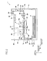
- the inkjet printer 1 includes an upper housing 1a (as an example of a second housing) and a lower housing 1b (as an example of a first housing) each of which has a rectangular parallelepiped shape and which have substantially the same size.
- the upper housing 1a has an opening on a lower surface thereof and the lower housing 1b has an opening on an upper surface thereof.
- an internal space of the inkjet printer 1 is defined as shown in Fig. 2 .
- a sheet-discharge portion 31 is disposed in an upper portion of a top panel of the upper housing 1a.
- a sheet feed path through which a recording sheet P is fed from a sheet-feed unit 1c (described later) to the sheet-discharge portion 31 along a thick arrow shown in Fig. 2 .
- the upper housing 1a is connected to the lower housing 1b via a shaft 1h which is disposed at a side of a bottom end of the upper housing 1a and extends in a main scanning direction.
- the upper housing 1a is pivotable about the shaft 1h relative to the lower housing 1b.
- the upper housing 1a is pivotable between a close position, a position shown in Fig. 2 , in which the upper housing 1a is adjacent to the lower housing 1b and a distant position, a position shown in Fig. 1 , at which the upper housing 1a is positioned farther away from the lower housing 1b than the upper housing 1a at the close position.
- the jam treatment is a work in which the user removes a jammed recording sheet P in the sheet feed path during a recording operation.
- the maintenance works in the recording portion 9 includes a work in which the user removes a foreign matter adhered to an ejection surface 10a, a work in which the user adjusts a position in which a head 10 is disposed, a work in which the user replaces the head 10 with another, and so on.
- the maintenance works in the supporting portion 60 includes a work in which the user removes a foreign matter adhered to a supporting surface 61a, a work in which the user adjusts a position in which the supporting portion 60 is disposed, a work in which the user replaces the supporting portion 60 with another, and so on.
- the maintenance works includes a cleaning work and a replacement work of composing elements that are accommodated in the upper housing 1a and the lower housing 1b such as a sheet-supply roller 21, guides 20, and pairs of feed rollers 22 through 28.
- a spring (not shown) which applies a force to the upper housing 1a in a direction in which the upper housing 1a is opened or moved from the close position to the distant position.
- the upper housing 1a can be opened up to an inclined angle of about 35 degrees with respect to a horizontal surface.
- the distant position of the upper housing 1a is not limited to the position shown in Fig. 1 .
- the distant position can be a position that is different from the close position and at which the upper housing 1a is distant farther from the lower housing 1b than at the close position.
- a lock mechanism 70 which limits a pivot of the upper housing 1a at the close position.
- a cover 1d which covers the front side of the upper housing 1a and can be opened and closed.
- the cover 1d is pivotable about a shaft 1g that is disposed in a lower end of the cover 1d such that the front side of the upper housing 1a is opened and closed.
- the user first opens the cover 1d and releases a limitation by the lock mechanism 70.
- the upper housing 1a is then pivoted from the close position to the distant position.
- the pivot of the upper housing 1a is limited by the lock mechanism 70, and then the cover 1d is closed.
- the upper housing 1a there are accommodated two heads 10 (a pre-coat head 10 which ejects a pretreatment liquid and an inkjet head 10 which ejects a black ink, in an order from an upstream side in a sheet feed direction shown in the thick arrow in Fig. 2 ), a frame 3 which supports the two heads 10 and an upper one of a pair of feed rollers 24, the two cartridges 35 which are respectively mounted in two cartridge mount portions 80 (as an example of a tank mount portion), and a controller 1p (shown in Fig. 2 ) which controls operations of respective portions of the printer 1.
- the two heads 10 and the frame 3 constitute the recording portion 9 which records an image on the recording sheet P.
- the two heads 10 are held by the upper housing 1a through the frame 3.
- the upper housing 1a there are also accommodated upper rollers 25, 26 of two pairs of feed rollers 25, 26, an upper guide 29 of two guides 29 that are disposed between the feed rollers 25, 26, two pairs of feed rollers 27, 28, and two pairs of guides 29 that are disposed between the two pairs of feed rollers 26, 28 in the sheet feed direction.
- the upper housing 1a is pivoted from the close position to the distant position, the above-described accommodated components are all moved with the upper housing 1a.
- Fig. 2 an illustration of some components that are accommodated in the upper housing 1a is omitted.
- the lower housing 1b accommodates or retains the supporting portion 60 and the sheet-feed unit 1c.
- the lower housing 1b also accommodates a sheet sensor 32, two pairs of feed rollers 22, 23, and two pairs of guides 29 that are disposed between the sheet-feed unit 1c and the pair of feed rollers 23 in the sheet feed direction.
- Each cartridge 35 (as an example of a tank) stores the pretreatment liquid or the black ink as a recording agent that is supplied to a corresponding head 10.
- the pretreatment liquid and the black ink are generally referred to as a liquid.
- the pretreatment liquid is a liquid for preventing an ink bleeding (leaking) and exuding, for improving a chromogenic effect and a fast-dry effect, and so forth.
- the cartridge 35 has a rectangular parallelepiped configuration. As shown in Fig. 3C , in a front surface 35a of the cartridge 35 as a surface of the cartridge 35 on a downstream portion in a mounting direction of the cartridge 35 relative to the cartridge mount portion 80, there are disposed a liquid supply portion 36 and a contact 37.
- the liquid supply portion 36 and the contact 37 are arranged side by side in the main scanning direction.
- the liquid supply portion 36 consists of an elastic member such as rubber that seals an opening formed in the front surface 35a of the cartridge 35.
- a hollow needle 86 penetrates through the liquid supply portion 36, i.e., the elastic member, and the cartridge 35 is connected to the corresponding head 10 through a tube (not shown) and a pump (not shown) that are connected to the hollow needle 86.
- the liquid stored in the cartridge 35 is supplied to the head 10.
- each pump is driven by the controller 1p only in a case where the liquid is forcibly supplied to the corresponding head, i.e., in a case where a purging operation is performed or an initial induction of the liquid is performed. Because a negative pressure occurs in a channel in the head 10 during an image recording, the liquid in the cartridge 35 is automatically supplied to the head 10.
- the contact 37 of the cartridge 35 is a contact of 1C chip type in which liquid data, e.g., a sort and an amount of liquid, and so on are stored.
- the contact 37 may be a contact which supplies electricity to a sensor or the like that is disposed in the cartridge 35.
- Each head 10 is a line-type head extending in the main scanning direction and having a generally rectangular parallelepiped configuration. Two heads 10 are distanced from each other in a sub-scanning direction and supported by the frame 3. Each head 10 is supported by the frame 3 so as to be opposed to the supporting portion 60 at an interval suitable for the recording in the state in which the upper housing 1a is at the close position.
- a lower surface of each head 10 is an ejection surface 10a in which a plurality of nozzles or ejection openings are formed. Further, there is formed a channel in each head 10 through which the liquid supplied from the cartridge 35 is sent to the nozzles.
- the sheet-supply unit 1c includes a sheet-supply tray 20 and the sheet-supply roller 21.
- the sheet-supply tray 20 is detachably attached to the lower housing 1b in the sub-scanning direction.
- the sheet-supply tray 20 is a box-like member opening upward and can accommodate the recording sheets P with a plurality of sizes.
- the sheet-supply roller 21 is rotated by controlling of the controller 1p so as to supply an uppermost one of the recording sheets P stored in the sheet-supply tray 20.
- the recording sheet P supplied by the sheet-supply roller 21 is fed to the supporting portion 60, guided by the guides 29 and nipped by the feed rollers 22, 23, in order.
- the supporting portion 60 is located to be opposed to the recording portion 9 in a vertical direction.
- the supporting portion 60 includes two platens 61 which are respectively opposed to the corresponding heads 10, and a frame 11 which supports the platens 61.
- the frame 11 rotatably supports a lower one of the pair of the feed rollers 24.
- Each platen 61 has a size that is slightly larger than that of the ejection surface 10a of each head 10 in the main scanning direction and in the sub-scanning direction and is opposed to the ejection surface 10a in the vertical direction.
- An upper surface of the platen 61 is the supporting surface 61a which is opposed to the ejection surface 10a and supports the recording sheet P.
- a material and working (processing) are devised so as to be suitable for supporting of the recording sheet P.
- a lightly-adhesive silicon layer is formed on the supporting surface 61a or that a multiplicity of ribs in the sub-scanning direction are formed on the supporting surface 61a prevents the recording sheet P placed on the supporting surface 61a from rising from the supporting surface 61a.
- the platen 61 is formed of a resin.
- the controller 1p when the controller 1p receives a command for the recording from an external device, based on the recording command, the controller 1p drives a sheet-supply motor (not shown) for the sheet-supply roller 21, feed motors (not shown) for the respective pairs of feed rollers 22 through 28, and so on.
- the recording sheet P supplied from the sheet-supply tray 20 is fed to the supporting portion 60 through the guides 29.
- the recording sheet P sent to the supporting portion 60 is conveyed, supported by the supporting surface 61a and nipped by the pairs of feed rollers 23, 24, 25 that are rotated.
- each head 10 is driven by the control of the controller 1p to eject the liquid through the nozzles of each ejection surface 10a toward a surface of the recording sheet P, so that an image is formed on the recording sheet P.
- An ink ejection from the nozzles of each head 10 is performed based on a detection signal from the sheet sensor 32 under the control of the controller 1p.
- the recording sheet P is then fed upward, guided by the guides 29 and nipped by the pairs of feed rollers 26, 27, 28, and discharged to the sheet-discharge portion 31 through an opening 30 that is formed in an upper portion of the upper housing 1a.
- the controller 1p can detect whether a jamming (a jamming of the recording sheet P in the sheet feed path) occurs. More precisely, the jamming is detected by the controller 1p, based on signals from the sheet sensor 32 and/or respective drive motors of the pair of feed motors 22 through 28. In a case where the jamming occurs during the recording operation, the controller 1p controls the heads 10 and the respective motors such that the recording operation is stopped (suspended).
- a jamming a jamming of the recording sheet P in the sheet feed path
- the user opens the cover 1d and, after the limitation by the lock mechanism 70 is released, pivots the upper housing 1a from the close position to the distant position.
- the upper housing 1a is returned to the close position.
- the pivot of the upper housing 1a is limited by the lock mechanism 70 and the cover 1d is closed. The jam treatment is thus finished.
- the recording operation starts when the controller 1p again receives the recording command from the external device.
- the two cartridge mount portions 80 are disposed in the upper portion of the upper housing 1a. As shown in Fig. 1 and Fig. 3A , the two cartridge mount portions 80 are arranged side by side in the main scanning direction. As shown in Fig. 3A , the two cartridge mount portions 80 are formed symmetrically with respect to a line L (indicated by a two-dot chain line in Fig. 3A ) which passes on just a middle of the two cartridge mount portions 80 in the main scanning direction and extends in the vertical direction. In the present embodiment, because the two cartridge mount portions 80 have the same structure, one of the two cartridge portions 80 will be described as follows.
- the cartridge mount portion 80 has a recessed portion 81 to which the cartridge 35 having a generally rectangular parallelepiped shape is attachable.
- An opening 81b of the recessed portion 81 is an insertion opening in which the cartridge 35 is inserted and is formed in the front surface of the upper housing 1a.
- the recessed portion 81 extends from the opening 81b toward the downstream portion in the mounting direction of the cartridge 35 in the cartridge mount portion 80. Accordingly, the mounting direction of the cartridge 35 in the cartridge mount portion 80 is a horizontal direction in the state in which the upper housing 1a is at the close position, as shown in Fig.
- a contact 83 and the hollow needle 86 in a bottom portion 82 are disposed as a downstream surface of the recessed portion 81 in the mounting direction of the cartridge 35 in the cartridge mount portion 80.
- the contact 83 and the hollow needle 86 are arranged side by side in the main scanning direction.
- a state in which the cartridge 35 is thoroughly mounted in the recessed portion 81 is a state in which the cartridge 35 is positioned at a position where the cartridge 35 is arranged when the hollow needle 86 penetrates through the liquid supply portion 36.
- the contact 83 in the present embodiment consists of an IC board.
- the contact 83 may be a contact which is electrically connected to a contact which supplies electric power to a sensor and so on that are disposed in the cartridge 35.
- the hollow needle 86 protrudes from the bottom portion 82 along the mounting direction of the cartridge 35.
- the hollow needle 86 is connected to the tube (not shown) that is connected to the head 10. When the hollow needle 86 penetrates through the liquid supply portion 36, the cartridge 35 is connected to the corresponding head 10 that is opposed to the cartridge 35.
- a penetrating portion 84 at a position adjacent to the contact 83 and the hollow needle 86.
- the penetrating portion 84 is disposed at a lower inner surface 81a of the recessed portion 81.
- a resistance applying mechanism 90 in the penetrating portion 84 of the cartridge mount portion 80.
- the resistance applying mechanism 90 includes a pivot member 91 (as an example of a moving body), an engaging portion 95 and a spring 92.
- the penetrating portion 84 is located at a position that is aligned with the hollow needle 86 in the mounting direction of the cartridge 35 in the cartridge mount portion 80. In other words, the resistance applying mechanism 90 is located at the position that is aligned with the hollow needle 86 in the mounting direction of the cartridge 35 in the cartridge mount portion 80.
- the penetrating portion 84 may be disposed at a left, a right or an upper inner surface of the recessed portion 81 other than the lower inner surface 81a of the recessed portion 81, and the resistance applying mechanism 90 may be disposed therein.
- the pivot member 91 is pivotably supported by a shaft 89 which is disposed in the penetrating portion 84 and extends in the main scanning direction.
- the penetrating portion 84 is located on an upstream portion of the contact 82 and an end of the hollow needle 86 in the inner surface 81a in the mounting direction.
- the pivot member 91 is located so as to apply the resistance to the cartridge 35 on the upstream portion of the contact 83 and the end of the hollow needle 86 in the mounting direction. As shown in Fig.
- the pivot member 91 includes a horizontal portion 91a which extends horizontally in the sub-scanning direction in the state in which the upper housing 1a is at the close position and an inclining portion 91b which extends obliquely downward from one of opposite ends of the horizontal portion 91a, and has a L-shaped configuration.
- An upper surface of the horizontal portion 91a constitutes a part of the lower inner surface 81a of the recessed portion 81 in the state in which the upper housing 1a is at the close position.
- One of opposite ends of the coil spring 92 (as an example of a force applying portion) is fixed to a lower end portion of the inclining portion 91b, i.e., one of opposite end portions thereof that is farther away from the shaft 89.
- the other end of the spring 92 is fixed to a flange 93 that is formed in a lower surface of the cartridge mount portion 80. Accordingly, the pivot member 91 is applied a force by the spring 92 in a clockwise direction in Fig. 3B .
- the coil spring 92 is adopted as the force applying portion, but any elastic member can be adopted as long as the elastic member can apply a force to the pivot member 91 in the clockwise direction in Fig. 3B .
- the spring 92 is also supported by the upper housing 1a.
- a projecting portion 97 In the lower end portion of the inclining portion 91b, there is formed a projecting portion 97.
- a stopper 94 is formed in the vicinity of the inclining portion 91b.
- the projecting portion 97 and the stopper 94 constitute a limiting portion 96 which limits a range of pivot of the pivot member 91.
- the contact between the projecting portion 97 and the stopper 94 limits the pivot range of the pivot member 91 such that the horizontal portion 91a stays (maintains) at a projecting position (described later).
- the pivot member 91 is prevented from pivoting too much by the spring 92 and is positioned at the projecting position, so that, in the cartridge mount portion 80, the cartridge 35 can be certainly stopped from moving in the mounting direction in the state in which the upper housing 1a is at the distant position.
- the two engaging portions 95 are respectively formed on respective upper ends of two frames 1e that are components of the lower housing 1b. As shown in Fig. 3B , each engaging portion 95 is formed so as to be opposed to the corresponding penetrating portion 84 in the state in which the upper housing 1a is at the close position.
- the engaging portion 95 also includes an inclined surface 95a which is engageable with the inclined portion 91b in the state in which the upper housing 1a is at the close position. Further, since the engaging portion 95 is engaged with the inclined portion 91b when the upper housing 1a is pivoted from the distant position to the close position, the pivot member 91 is pivoted in a counterclockwise direction in Fig. 3B .
- the resistance applying mechanism 90 operates simultaneously with the pivot of the upper housing 1a.
- the pivot member 91 of the resistance applying mechanism 90 is applied the force by the spring 92, but the pivot of the pivot member 91 is limited because the inclining portion 9 1 b and the engaging portion 95 are engaged with each other. Therefore, the pivot member 91 is positioned at a retracted position at which the other end of the horizontal portion 91a does not project to the recessed portion 81, i.e., does not project from the lower inner surface 81a.
- an inclined surface 91d which is inclined from a top end portion 91c of the horizontal portion 91a toward the upstream portion thereof in the mounting direction is greater in angle with respect to the lower inner surface 81a than an inclined surface 91e which is inclined from the top end portion 91c of the horizontal portion 91a toward a downstream portion thereof in the mounting direction.
- the pivot member 91 When the upper housing 1a is pivoted from the distant position to the close position, a bottom end of the inclining portion 91b first contacts the inclined surface 95a of the engaging portion 95. Then, as the upper housing 1a approaches the close position, the inclining portion 91b is pressed by the inclined surface 95a. When the upper housing 1a reaches the close position, the pivot member 91 is positioned at the retracted position due to the engagement with the engaging portion 95. The engaging portion 95 is engaged with the inclining portion 91b against the force of the spring 92 such that the pivot member 91 moves from the projecting position to the retracted position. Thus, the pivot member 91 can be selectively positioned at the projecting position or at the retracted position corresponding to the pivot of the upper housing 1a.
- the pivot member 91 is positioned at the retracted position. At this time, even when the cartridge 35 is mounted in the cartridge mount portion 80, the cartridge 35 can be mounted in the cartridge mount portion 80 without being caught on the pivot member 91. Further, in the state in which the upper housing 1a is at the close position, the mounting direction of the cartridge 35 in the cartridge mount portion 80 is in parallel with the horizontal direction or the sub-scanning direction. Thus, the cartridge 35 can be mounted in the cartridge mount portion 80 with a given mounting force by the user. Accordingly, without a high-impact between the contacts 37, 83 and between the liquid supply portion 36 and the hollow needle 86, and without a damage of the cartridge 35 and the cartridge mount portion 80, the cartridge 35 can be mounted in the cartridge mount portion 80.
- the cartridge 35 When the upper housing 1a is pivoted from the close position to the distant position in a state in which a front end of the cartridge 35 in the mounting direction or a downstream end of the cartridge 35 in the mounting direction is inserted into the recessed portion 81 of the cartridge mount portion 80, the cartridge 35 operates simultaneously with the pivot of the upper housing 1a and is moved obliquely downward, i.e., in the direction including the downward component in the vertical direction relative to the cartridge mount portion 80. Further, when the cartridge 35 is inserted into the recessed portion 81 of the cartridge mount portion 80 in a state in which the upper housing 1a is at the distant position, as shown in Fig. 3C , the mounting direction of the cartridge 35 relative to the cartridge mount portion 80 extends obliquely downward, i.e., in the direction including the downward component in the vertical direction.
- the pivot member 91 is positioned at the projecting position. Therefore, even when the cartridge 35 quickly and actively moves from a position indicated by a two-dot chain line in Fig. 3C in the mounting direction, the movement of the cartridge 35 is stopped by the pivot member 91. In other words, before the cartridge 35 is thoroughly mounted in the cartridge mount portion 80, an end of the pivot member 91 at the projecting position and the cartridge 35 are in contact with each other, and the resistance for stopping of the movement of the cartridge 35 is applied by the pivot member 91.
- the resistance force is a force different from the kinetic friction force that occurs due to the contact between the cartridge 35 and the left and the right inner surfaces and the upper and the lower inner surfaces of the recessed portion 81 and a force which acts in an opposite direction to the mounting direction.
- An impact power due to the contact with the cartridge 35 and the pivot member 91 is smaller than an impact power due to the contact with the cartridge 35 and the cartridge mount portion 80 when the cartridge 35 is moved to a position at which the cartridge 35 is completely mounted in the cartridge mount portion 80.
- the cartridge 35 and the pivot member 91 are free of damage by the contact with them. Since the movement of the cartridge 35 is stopped by the pivot member 91, without having a high-impact on the contacts 37, 83 and the liquid supply portion 36 and the hollow needle 86, the cartridge 35 and the cartridge mount portion 80 are prevented from being damaged.
- the resistance is applied to the cartridge 35 by the pivot member 91, in addition to the kinetic friction force between the cartridge 35 and the inner surface 81a.
- the impact between the cartridge mount portion 80 and the cartridge 35 can be restrained. Accordingly, the cartridge mount portion 80 and the cartridge 35 are less subject to the damage.
- the user obtains the workspace.
- the upper housing 1a is at the distant position and the workspace for the user is secured, the user can perform the jam treatment and the maintenance works in the recording portion 9 and the supporting portion 60.
- the upper housing 1a is pivoted from the close position to the distant position in order that the user performs the jam treatment and the maintenance works in the recording portion 9 and the supporting portion 60, and the upper housing 1a is not pivoted in order that the cartridge 35 is inserted into or extracted from the upper housing 1a.
- the upper housing 1a is pivoted for the purpose different from the insertion and extraction of the cartridge 35.
- the upper housing 1a is pivoted from the close position to the distant position in a state in which the cartridge 35 is in the process of the mounting in the cartridge mount portion 80, or a case where the cartridge 35 is mounted in the cartridge mount portion 80 in a state in which the upper housing 1a is at the distant position.
- the impact between the cartridge mount portion 80 and the cartridge 35 can be restrained, so that the cartridge mount portion 80 and the cartridge 35 are restrained from being damaged.
- the pivot member 91 is located on the upstream portion of the contact 83 and the end of the hollow needle 86 in the inner surface 81a in the mounting direction.
- the resistance can be applied to the cartridge 35 on the upstream portion of the contact 83 and the end of the hollow needle 86 in the mounting direction. Accordingly, the contact 83 and the hollow needle 86 can be restrained from being damaged.
- the contact 83 and the contact 37 of the cartridge 35 are electrically connected to each other.
- the contacts 83, 37 that are electrically connected are deformed, there is the possibility that the contacts 83, 37 cannot be electrically connected to each other.
- the contacts 37, 83 are restrained from being deformed, so that the damage of the cartridge 35 and the cartridge mount portion 80 can be restrained.
- the pivot member is located at a position more distanced from the contact 83 and the hollow needle 86 than a center of the recessed portion 81 in the main scanning direction, when the cartridge 35 is mounted in the recessed portion 81 in the state in which the upper housing 1a is at the distant position, there is the possibility that the cartridge 35 is rotated about a contact point of the cartridge 35 and the pivot member as a center of the rotation and the cartridge 35 contacts the contact 83 and the hollow needle 86.
- the pivot member 91 is located to be adjacent to the contact 83 and the hollow needle 86 in the main scanning direction. Therefore, the damage of the contact 83 and the hollow needle 86 can be more certainly restrained.
- the resistance applying mechanism 90 includes the pivot member 91 which is pivotable between the retracted position and the projecting position, the cartridge 35 can be stopped from moving in the mounting direction. Further, the pivot member 91 is at the retracted position when the upper housing 1a is at the close position, so that, when the upper housing 1a is at the close position, the cartridge 35 can be easily mounted in the cartridge mount portion 80.
- the resistance applying mechanism 90 also includes the spring 92 which applies the force to the pivot member 91 and the engaging portion 95 which is engaged with the pivot member 91, simultaneously with the pivot of the upper housing 1a, the pivot member 91 can be surely moved between the projecting position and the retracted position.
- the upper housing 1a supports the recording portion 9 and the lower housing 1b supports the supporting portion 60, when the upper housing 1a is pivoted from the close position to the distant position, the user can perform the maintenance work in which the jammed recording sheet P is removed between the recording portion 9 and the supporting portion 60, the maintenance work in the recording portion 9, and the maintenance work in the supporting portion 60.
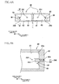
- a resistance applying mechanism 290 as shown in Figs. 4A and 4B may be adopted. As shown in Fig. 4A , each of the two resistance applying mechanisms 290 in the modified embodiment is disposed in the bottom portion 82 of the recessed portion 81 of each cartridge mount portion 80. Each resistance applying mechanism 290 includes two elastic bodies 291 that are arranged side by side in the main scanning direction.
- the elastic body 291 includes a spring 292 which is located in a circular hole 82b that is formed in the bottom portion 82, and a cylindrical portion 293 which is fixed to the spring 292.
- a diameter of the cylindrical portion 293 is slightly smaller than that of the hole 82b.
- the cylindrical portion 293 is applied a force by the spring 292 such that, when no cartridge 35 is mounted in the cartridge mount portion 80, the cylindrical portion 293 is positioned at a projecting position, a position shown in Fig. 4B , at which a part of the cylindrical portion 293 is projected from the hole 82b. In a state in which the cylindrical portion 293 is at the projecting position, an end of the cylindrical portion 293 is located on an upstream portion of the end of the hollow needle 86 in the mounting direction.
- the user pushes the cartridge 35 into the cartridge mount portion 80 with a force larger than the force by the spring 292 such that the cartridge 35 can be mounted in the cartridge mount portion 80.
- the two elastic bodies 291 constitute the resistance applying mechanism 290, so that a structure of the resistance applying mechanism 290 is simplified.
- the resistance applying mechanism 290 in the modified embodiment may consist of one elastic body 291. In this case, it is desirable that the elastic body 291 is located in a position adjacent to the contact 83 and the hollow needle 86.
- the printer 1 in the above-mentioned embodiments includes the cartridges 35, but the recording apparatus to which the present invention is applied may include no cartridges 35.
- the recording apparatus may include the cartridge mount portion 80 in which the cartridge 35 can be mounted. Three or more cartridge mount portions 80 may be disposed in the main scanning direction or a plurality of the cartridge mount portions 80 may be aligned with each other in the vertical direction.
- the cartridge includes a reservoir portion which stores the pretreatment liquid and the ink as a recording agent that are supplied to the heads 10 in order to record an image on the recording sheet
- the cartridge may also include waste liquid reservoir portion which stores a waste liquid that is discharged from the heads 10.
- the contact 37 of the cartridge 35 may not be a contact that is electrically connected to the contact 83.
- the contact 37 is enough to have a structure to contact the contact 83.
- the contact 83 may not be a contact that is electrically connected to the contact 37 of the cartridge 35.
- the contact 83 may be a mechanical switch which outputs a detection signal when the contact 83 is pressed due to the contact thereof with the contact 37 of the cartridge 35.
- the present invention is applicable to any one of a line-type printer and a serial-type printer. Further, the present invention is, not limited to a printer, applicable to a facsimile machine, a copier machine, and so forth, and also applicable to a recording apparatus which performs a recording operation by ejecting liquid except ink.
- the present invention is not limited to an inkjet recording apparatus, and is applicable to, for example, a laser-type recording apparatus, a thermal-type recording apparatus and so on.
- the recording media are not limited to the recording sheets P, and may be various recordable media.
- the resistance applying mechanism 90 may be located in a position that is aligned with the contact 83 in the mounting direction of the cartridge 35 in the cartridge mount portion 80.
- the resistance applying mechanisms 90, 290 may be disposed in the vicinity of the opening 81b of the cartridge mount portion 80. In other words, the resistance applying mechanisms 90, 290 may be located far distanced from the contact 83 and so on.
- the resistance applying mechanism 90 may have no limiting portion 96. Further, in the state in which the pivot member 91 is at the projecting position, the angle of the inclined surface 91d of the horizontal portion 91a with respect to the lower inner surface 81a may be smaller than that of the inclined surface 91eor may be the same as that of the inclined surface 91 e.
- the elastic body 291 may be formed of an elastic material such as rubber.
Landscapes
- Ink Jet (AREA)
- Printers Characterized By Their Purpose (AREA)
Applications Claiming Priority (1)
| Application Number | Priority Date | Filing Date | Title |
|---|---|---|---|
| JP2011079592A JP5382044B2 (ja) | 2011-03-31 | 2011-03-31 | 記録装置 |
Publications (3)
| Publication Number | Publication Date |
|---|---|
| EP2505371A2 true EP2505371A2 (fr) | 2012-10-03 |
| EP2505371A3 EP2505371A3 (fr) | 2013-02-27 |
| EP2505371B1 EP2505371B1 (fr) | 2014-09-17 |
Family
ID=45954400
Family Applications (1)
| Application Number | Title | Priority Date | Filing Date |
|---|---|---|---|
| EP12161484.6A Active EP2505371B1 (fr) | 2011-03-31 | 2012-03-27 | Appareil d'enregistrement |
Country Status (3)
| Country | Link |
|---|---|
| US (3) | US9004676B2 (fr) |
| EP (1) | EP2505371B1 (fr) |
| JP (1) | JP5382044B2 (fr) |
Families Citing this family (7)
| Publication number | Priority date | Publication date | Assignee | Title |
|---|---|---|---|---|
| JP5343994B2 (ja) | 2011-03-31 | 2013-11-13 | ブラザー工業株式会社 | 記録装置 |
| EP2586618B1 (fr) | 2011-10-31 | 2014-09-24 | Brother Kogyo Kabushiki Kaisha | Appareil d'enregistrement doté d'un dispositif de transport pour un support d'enregistrement |
| EP2586617B1 (fr) * | 2011-10-31 | 2014-09-24 | Brother Kogyo Kabushiki Kaisha | Appareil d'enregistrement à mécanisme de convoyage sur support d'enregistrement |
| US8662661B2 (en) * | 2011-10-31 | 2014-03-04 | Brother Kogyo Kabushiki Kaisha | Liquid ejection apparatus having first casing and second casing rotatable relative to first casing |
| EP2599635B1 (fr) | 2011-11-30 | 2014-11-05 | Brother Kogyo Kabushiki Kaisha | Dispositif d'éjection d'un liquide |
| JP6171313B2 (ja) * | 2011-12-08 | 2017-08-02 | セイコーエプソン株式会社 | 液体噴射装置 |
| JP6135073B2 (ja) * | 2012-09-01 | 2017-05-31 | 株式会社リコー | 画像形成装置 |
Citations (1)
| Publication number | Priority date | Publication date | Assignee | Title |
|---|---|---|---|---|
| JP2004345307A (ja) | 2003-05-26 | 2004-12-09 | Canon Finetech Inc | 記録装置 |
Family Cites Families (36)
| Publication number | Priority date | Publication date | Assignee | Title |
|---|---|---|---|---|
| JPS58116182A (ja) | 1981-12-29 | 1983-07-11 | Fujitsu Ltd | カバ−開放検出機構 |
| JPS60172575A (ja) | 1984-02-20 | 1985-09-06 | Canon Electronics Inc | プリンタ |
| EP0598701B1 (fr) | 1986-12-10 | 1998-03-25 | Canon Kabushiki Kaisha | Appareil d'enregistrement et méthode de remise en état de décharges |
| JP2617933B2 (ja) | 1987-04-13 | 1997-06-11 | キヤノン株式会社 | インクジエツト記録装置 |
| JPH0682245B2 (ja) * | 1987-12-22 | 1994-10-19 | キヤノン株式会社 | 画像形成装置 |
| JPH066377Y2 (ja) * | 1989-10-25 | 1994-02-16 | ブラザー工業株式会社 | 感光体カートリッジ |
| JPH0798402B2 (ja) * | 1990-07-26 | 1995-10-25 | ブラザー工業株式会社 | レーザプリンタ |
| JP3049888B2 (ja) | 1991-11-08 | 2000-06-05 | ブラザー工業株式会社 | 印字装置 |
| JPH0651582A (ja) * | 1992-07-30 | 1994-02-25 | Brother Ind Ltd | 電子写真装置 |
| JPH082754A (ja) * | 1994-06-22 | 1996-01-09 | Matsushita Graphic Commun Syst Inc | インクジェット記録装置 |
| JPH09258576A (ja) * | 1996-03-25 | 1997-10-03 | Ricoh Co Ltd | 複写装置 |
| JP3715797B2 (ja) | 1998-09-22 | 2005-11-16 | キヤノン株式会社 | シート吸着搬送装置及び記録装置 |
| EP1289761B1 (fr) | 2000-05-24 | 2006-05-17 | Silverbrook Research Pty. Limited | Element platine rotatif |
| JP2002001987A (ja) * | 2000-06-23 | 2002-01-08 | Canon Inc | インクジェット方式画像形成装置 |
| US20040051764A1 (en) * | 2002-09-13 | 2004-03-18 | Cook Brian Dale | Easy install ink tank for an ink jet off-carrier system |
| US7008051B2 (en) * | 2002-10-10 | 2006-03-07 | Akermalm Per G | Expanded ink supply system for ink jet printers |
| JP4432416B2 (ja) | 2003-09-12 | 2010-03-17 | 富士ゼロックス株式会社 | 記録装置 |
| JP4273896B2 (ja) | 2003-09-24 | 2009-06-03 | ブラザー工業株式会社 | インクジェットプリンタ |
| JP2005199521A (ja) * | 2004-01-14 | 2005-07-28 | Brother Ind Ltd | 画像形成装置、プロセスカートリッジ及び露光走査装置 |
| JP2006044128A (ja) | 2004-08-06 | 2006-02-16 | Ricoh Co Ltd | 画像形成装置 |
| EP1640820B1 (fr) * | 2004-08-06 | 2011-12-14 | Brother Kogyo Kabushiki Kaisha | Cartouches de révélateur avec une partie extérieure en saillie |
| JP2006142608A (ja) | 2004-11-18 | 2006-06-08 | Canon Inc | プリント装置及びプリント制御方法 |
| UA91582C2 (ru) * | 2005-12-26 | 2010-08-10 | Сейко Эпсон Корпорейшн | контейнер с материалом для печати и плата, устанавливаемая в контейнере с материалом для печати |
| JP4144637B2 (ja) | 2005-12-26 | 2008-09-03 | セイコーエプソン株式会社 | 印刷材収容体、基板、印刷装置および印刷材収容体を準備する方法 |
| JP4605394B2 (ja) * | 2006-03-31 | 2011-01-05 | ブラザー工業株式会社 | インクカートリッジの収納装置に対する保護装置 |
| JP4697453B2 (ja) * | 2006-06-29 | 2011-06-08 | セイコーエプソン株式会社 | カートリッジの着脱装置、記録装置及び液体噴射装置 |
| US7986420B2 (en) | 2006-11-29 | 2011-07-26 | International Business Machines Corporation | Sensing paper jam, out-of-paper, and cover open in a printer |
| JP5182466B2 (ja) * | 2007-02-07 | 2013-04-17 | セイコーエプソン株式会社 | 液体カートリッジ着脱装置および液体噴射装置 |
| US7654640B2 (en) * | 2007-03-21 | 2010-02-02 | Silverbrook Research Pty Ltd | Printhead with drive circuitry components adjacent the printhead IC |
| US8136929B2 (en) | 2007-06-20 | 2012-03-20 | Seiko Epson Corporation | Installing fluid container in fluid ejection device |
| JP4766011B2 (ja) * | 2007-06-20 | 2011-09-07 | セイコーエプソン株式会社 | 流体噴射装置およびその製造方法 |
| WO2008156202A1 (fr) | 2007-06-20 | 2008-12-24 | Seiko Epson Corporation | Appareil d'injection de fluide, et son procédé de fabrication |
| JP4952655B2 (ja) * | 2008-05-22 | 2012-06-13 | セイコーエプソン株式会社 | 流体噴射装置およびその製造方法 |
| JP2009072931A (ja) | 2007-09-19 | 2009-04-09 | Ryobi Ltd | 印刷機の表面処理装置におけるカバーロック機構 |
| JP2010208038A (ja) * | 2009-03-06 | 2010-09-24 | Seiko Epson Corp | 液体噴射装置及び液体収容容器 |
| JP5343994B2 (ja) | 2011-03-31 | 2013-11-13 | ブラザー工業株式会社 | 記録装置 |
-
2011
- 2011-03-31 JP JP2011079592A patent/JP5382044B2/ja active Active
-
2012
- 2012-03-27 EP EP12161484.6A patent/EP2505371B1/fr active Active
- 2012-03-29 US US13/434,203 patent/US9004676B2/en not_active Ceased
-
2017
- 2017-04-14 US US15/487,744 patent/USRE47670E1/en active Active
-
2019
- 2019-09-24 US US16/580,382 patent/USRE48702E1/en active Active
Patent Citations (1)
| Publication number | Priority date | Publication date | Assignee | Title |
|---|---|---|---|---|
| JP2004345307A (ja) | 2003-05-26 | 2004-12-09 | Canon Finetech Inc | 記録装置 |
Also Published As
| Publication number | Publication date |
|---|---|
| JP5382044B2 (ja) | 2014-01-08 |
| EP2505371A3 (fr) | 2013-02-27 |
| US20120251166A1 (en) | 2012-10-04 |
| USRE48702E1 (en) | 2021-08-24 |
| EP2505371B1 (fr) | 2014-09-17 |
| US9004676B2 (en) | 2015-04-14 |
| JP2012213877A (ja) | 2012-11-08 |
| USRE47670E1 (en) | 2019-10-29 |
Similar Documents
| Publication | Publication Date | Title |
|---|---|---|
| USRE48702E1 (en) | Recording apparatus | |
| US8899706B2 (en) | Recording apparatus | |
| EP1733892B1 (fr) | Appareil de traitement de bourrage pour imprimante et procede associe | |
| US20130106967A1 (en) | Recording apparatus with recording-medium conveying mechanism | |
| US9617109B2 (en) | Image recording apparatus | |
| EP2565040B1 (fr) | Appareil d'éjection de liquide | |
| US9296233B2 (en) | Liquid ejecting device | |
| JP5892137B2 (ja) | 記録装置 | |
| CN115315354B (zh) | 喷墨记录装置 | |
| JP2011056840A (ja) | 記録装置 | |
| US8632158B2 (en) | Liquid ejection apparatus | |
| US8651602B2 (en) | Liquid ejection apparatus and method for supplying liquid | |
| US9016851B2 (en) | Recording apparatus | |
| US9199486B2 (en) | Recording apparatus | |
| US8833932B2 (en) | Recording apparatus | |
| US8276169B2 (en) | Medium processing device | |
| JP7171306B2 (ja) | 液体吐出装置 | |
| KR100484191B1 (ko) | 잉크젯프린터 | |
| JP2009234669A (ja) | トレイ送り装置、記録装置 |
Legal Events
| Date | Code | Title | Description |
|---|---|---|---|
| PUAI | Public reference made under article 153(3) epc to a published international application that has entered the european phase |
Free format text: ORIGINAL CODE: 0009012 |
|
| AK | Designated contracting states |
Kind code of ref document: A2 Designated state(s): AL AT BE BG CH CY CZ DE DK EE ES FI FR GB GR HR HU IE IS IT LI LT LU LV MC MK MT NL NO PL PT RO RS SE SI SK SM TR |
|
| AX | Request for extension of the european patent |
Extension state: BA ME |
|
| PUAL | Search report despatched |
Free format text: ORIGINAL CODE: 0009013 |
|
| AK | Designated contracting states |
Kind code of ref document: A3 Designated state(s): AL AT BE BG CH CY CZ DE DK EE ES FI FR GB GR HR HU IE IS IT LI LT LU LV MC MK MT NL NO PL PT RO RS SE SI SK SM TR |
|
| AX | Request for extension of the european patent |
Extension state: BA ME |
|
| RIC1 | Information provided on ipc code assigned before grant |
Ipc: B41J 29/13 20060101AFI20130123BHEP |
|
| 17P | Request for examination filed |
Effective date: 20130827 |
|
| RBV | Designated contracting states (corrected) |
Designated state(s): AL AT BE BG CH CY CZ DE DK EE ES FI FR GB GR HR HU IE IS IT LI LT LU LV MC MK MT NL NO PL PT RO RS SE SI SK SM TR |
|
| GRAP | Despatch of communication of intention to grant a patent |
Free format text: ORIGINAL CODE: EPIDOSNIGR1 |
|
| INTG | Intention to grant announced |
Effective date: 20140417 |
|
| GRAS | Grant fee paid |
Free format text: ORIGINAL CODE: EPIDOSNIGR3 |
|
| GRAA | (expected) grant |
Free format text: ORIGINAL CODE: 0009210 |
|
| AK | Designated contracting states |
Kind code of ref document: B1 Designated state(s): AL AT BE BG CH CY CZ DE DK EE ES FI FR GB GR HR HU IE IS IT LI LT LU LV MC MK MT NL NO PL PT RO RS SE SI SK SM TR |
|
| REG | Reference to a national code |
Ref country code: GB Ref legal event code: FG4D |
|
| REG | Reference to a national code |
Ref country code: CH Ref legal event code: EP |
|
| REG | Reference to a national code |
Ref country code: IE Ref legal event code: FG4D |
|
| REG | Reference to a national code |
Ref country code: AT Ref legal event code: REF Ref document number: 687494 Country of ref document: AT Kind code of ref document: T Effective date: 20141015 |
|
| REG | Reference to a national code |
Ref country code: DE Ref legal event code: R096 Ref document number: 602012003108 Country of ref document: DE Effective date: 20141030 |
|
| PG25 | Lapsed in a contracting state [announced via postgrant information from national office to epo] |
Ref country code: GR Free format text: LAPSE BECAUSE OF FAILURE TO SUBMIT A TRANSLATION OF THE DESCRIPTION OR TO PAY THE FEE WITHIN THE PRESCRIBED TIME-LIMIT Effective date: 20141218 Ref country code: FI Free format text: LAPSE BECAUSE OF FAILURE TO SUBMIT A TRANSLATION OF THE DESCRIPTION OR TO PAY THE FEE WITHIN THE PRESCRIBED TIME-LIMIT Effective date: 20140917 Ref country code: NO Free format text: LAPSE BECAUSE OF FAILURE TO SUBMIT A TRANSLATION OF THE DESCRIPTION OR TO PAY THE FEE WITHIN THE PRESCRIBED TIME-LIMIT Effective date: 20141217 Ref country code: LT Free format text: LAPSE BECAUSE OF FAILURE TO SUBMIT A TRANSLATION OF THE DESCRIPTION OR TO PAY THE FEE WITHIN THE PRESCRIBED TIME-LIMIT Effective date: 20140917 Ref country code: SE Free format text: LAPSE BECAUSE OF FAILURE TO SUBMIT A TRANSLATION OF THE DESCRIPTION OR TO PAY THE FEE WITHIN THE PRESCRIBED TIME-LIMIT Effective date: 20140917 |
|
| REG | Reference to a national code |
Ref country code: NL Ref legal event code: VDEP Effective date: 20140917 |
|
| REG | Reference to a national code |
Ref country code: LT Ref legal event code: MG4D |
|
| PG25 | Lapsed in a contracting state [announced via postgrant information from national office to epo] |
Ref country code: HR Free format text: LAPSE BECAUSE OF FAILURE TO SUBMIT A TRANSLATION OF THE DESCRIPTION OR TO PAY THE FEE WITHIN THE PRESCRIBED TIME-LIMIT Effective date: 20140917 Ref country code: CY Free format text: LAPSE BECAUSE OF FAILURE TO SUBMIT A TRANSLATION OF THE DESCRIPTION OR TO PAY THE FEE WITHIN THE PRESCRIBED TIME-LIMIT Effective date: 20140917 Ref country code: LV Free format text: LAPSE BECAUSE OF FAILURE TO SUBMIT A TRANSLATION OF THE DESCRIPTION OR TO PAY THE FEE WITHIN THE PRESCRIBED TIME-LIMIT Effective date: 20140917 Ref country code: RS Free format text: LAPSE BECAUSE OF FAILURE TO SUBMIT A TRANSLATION OF THE DESCRIPTION OR TO PAY THE FEE WITHIN THE PRESCRIBED TIME-LIMIT Effective date: 20140917 |
|
| REG | Reference to a national code |
Ref country code: AT Ref legal event code: MK05 Ref document number: 687494 Country of ref document: AT Kind code of ref document: T Effective date: 20140917 |
|
| PG25 | Lapsed in a contracting state [announced via postgrant information from national office to epo] |
Ref country code: NL Free format text: LAPSE BECAUSE OF FAILURE TO SUBMIT A TRANSLATION OF THE DESCRIPTION OR TO PAY THE FEE WITHIN THE PRESCRIBED TIME-LIMIT Effective date: 20140917 |
|
| PG25 | Lapsed in a contracting state [announced via postgrant information from national office to epo] |
Ref country code: PT Free format text: LAPSE BECAUSE OF FAILURE TO SUBMIT A TRANSLATION OF THE DESCRIPTION OR TO PAY THE FEE WITHIN THE PRESCRIBED TIME-LIMIT Effective date: 20150119 Ref country code: SK Free format text: LAPSE BECAUSE OF FAILURE TO SUBMIT A TRANSLATION OF THE DESCRIPTION OR TO PAY THE FEE WITHIN THE PRESCRIBED TIME-LIMIT Effective date: 20140917 Ref country code: RO Free format text: LAPSE BECAUSE OF FAILURE TO SUBMIT A TRANSLATION OF THE DESCRIPTION OR TO PAY THE FEE WITHIN THE PRESCRIBED TIME-LIMIT Effective date: 20140917 Ref country code: ES Free format text: LAPSE BECAUSE OF FAILURE TO SUBMIT A TRANSLATION OF THE DESCRIPTION OR TO PAY THE FEE WITHIN THE PRESCRIBED TIME-LIMIT Effective date: 20140917 Ref country code: EE Free format text: LAPSE BECAUSE OF FAILURE TO SUBMIT A TRANSLATION OF THE DESCRIPTION OR TO PAY THE FEE WITHIN THE PRESCRIBED TIME-LIMIT Effective date: 20140917 Ref country code: CZ Free format text: LAPSE BECAUSE OF FAILURE TO SUBMIT A TRANSLATION OF THE DESCRIPTION OR TO PAY THE FEE WITHIN THE PRESCRIBED TIME-LIMIT Effective date: 20140917 Ref country code: IS Free format text: LAPSE BECAUSE OF FAILURE TO SUBMIT A TRANSLATION OF THE DESCRIPTION OR TO PAY THE FEE WITHIN THE PRESCRIBED TIME-LIMIT Effective date: 20150117 |
|
| PG25 | Lapsed in a contracting state [announced via postgrant information from national office to epo] |
Ref country code: AT Free format text: LAPSE BECAUSE OF FAILURE TO SUBMIT A TRANSLATION OF THE DESCRIPTION OR TO PAY THE FEE WITHIN THE PRESCRIBED TIME-LIMIT Effective date: 20140917 Ref country code: PL Free format text: LAPSE BECAUSE OF FAILURE TO SUBMIT A TRANSLATION OF THE DESCRIPTION OR TO PAY THE FEE WITHIN THE PRESCRIBED TIME-LIMIT Effective date: 20140917 |
|
| REG | Reference to a national code |
Ref country code: DE Ref legal event code: R097 Ref document number: 602012003108 Country of ref document: DE |
|
| PLBE | No opposition filed within time limit |
Free format text: ORIGINAL CODE: 0009261 |
|
| STAA | Information on the status of an ep patent application or granted ep patent |
Free format text: STATUS: NO OPPOSITION FILED WITHIN TIME LIMIT |
|
| PG25 | Lapsed in a contracting state [announced via postgrant information from national office to epo] |
Ref country code: DK Free format text: LAPSE BECAUSE OF FAILURE TO SUBMIT A TRANSLATION OF THE DESCRIPTION OR TO PAY THE FEE WITHIN THE PRESCRIBED TIME-LIMIT Effective date: 20140917 |
|
| 26N | No opposition filed |
Effective date: 20150618 |
|
| PG25 | Lapsed in a contracting state [announced via postgrant information from national office to epo] |
Ref country code: IT Free format text: LAPSE BECAUSE OF FAILURE TO SUBMIT A TRANSLATION OF THE DESCRIPTION OR TO PAY THE FEE WITHIN THE PRESCRIBED TIME-LIMIT Effective date: 20140917 |
|
| PG25 | Lapsed in a contracting state [announced via postgrant information from national office to epo] |
Ref country code: MC Free format text: LAPSE BECAUSE OF FAILURE TO SUBMIT A TRANSLATION OF THE DESCRIPTION OR TO PAY THE FEE WITHIN THE PRESCRIBED TIME-LIMIT Effective date: 20140917 Ref country code: LU Free format text: LAPSE BECAUSE OF FAILURE TO SUBMIT A TRANSLATION OF THE DESCRIPTION OR TO PAY THE FEE WITHIN THE PRESCRIBED TIME-LIMIT Effective date: 20150327 |
|
| REG | Reference to a national code |
Ref country code: CH Ref legal event code: PL |
|
| PG25 | Lapsed in a contracting state [announced via postgrant information from national office to epo] |
Ref country code: SI Free format text: LAPSE BECAUSE OF FAILURE TO SUBMIT A TRANSLATION OF THE DESCRIPTION OR TO PAY THE FEE WITHIN THE PRESCRIBED TIME-LIMIT Effective date: 20140917 |
|
| REG | Reference to a national code |
Ref country code: IE Ref legal event code: MM4A |
|
| PG25 | Lapsed in a contracting state [announced via postgrant information from national office to epo] |
Ref country code: CH Free format text: LAPSE BECAUSE OF NON-PAYMENT OF DUE FEES Effective date: 20150331 Ref country code: LI Free format text: LAPSE BECAUSE OF NON-PAYMENT OF DUE FEES Effective date: 20150331 Ref country code: IE Free format text: LAPSE BECAUSE OF NON-PAYMENT OF DUE FEES Effective date: 20150327 |
|
| REG | Reference to a national code |
Ref country code: FR Ref legal event code: PLFP Year of fee payment: 5 |
|
| PG25 | Lapsed in a contracting state [announced via postgrant information from national office to epo] |
Ref country code: MT Free format text: LAPSE BECAUSE OF FAILURE TO SUBMIT A TRANSLATION OF THE DESCRIPTION OR TO PAY THE FEE WITHIN THE PRESCRIBED TIME-LIMIT Effective date: 20140917 |
|
| REG | Reference to a national code |
Ref country code: FR Ref legal event code: PLFP Year of fee payment: 6 |
|
| PG25 | Lapsed in a contracting state [announced via postgrant information from national office to epo] |
Ref country code: HU Free format text: LAPSE BECAUSE OF FAILURE TO SUBMIT A TRANSLATION OF THE DESCRIPTION OR TO PAY THE FEE WITHIN THE PRESCRIBED TIME-LIMIT; INVALID AB INITIO Effective date: 20120327 Ref country code: SM Free format text: LAPSE BECAUSE OF FAILURE TO SUBMIT A TRANSLATION OF THE DESCRIPTION OR TO PAY THE FEE WITHIN THE PRESCRIBED TIME-LIMIT Effective date: 20140917 Ref country code: BG Free format text: LAPSE BECAUSE OF FAILURE TO SUBMIT A TRANSLATION OF THE DESCRIPTION OR TO PAY THE FEE WITHIN THE PRESCRIBED TIME-LIMIT Effective date: 20140917 |
|
| PG25 | Lapsed in a contracting state [announced via postgrant information from national office to epo] |
Ref country code: TR Free format text: LAPSE BECAUSE OF FAILURE TO SUBMIT A TRANSLATION OF THE DESCRIPTION OR TO PAY THE FEE WITHIN THE PRESCRIBED TIME-LIMIT Effective date: 20140917 |
|
| PG25 | Lapsed in a contracting state [announced via postgrant information from national office to epo] |
Ref country code: BE Free format text: LAPSE BECAUSE OF FAILURE TO SUBMIT A TRANSLATION OF THE DESCRIPTION OR TO PAY THE FEE WITHIN THE PRESCRIBED TIME-LIMIT Effective date: 20140917 |
|
| REG | Reference to a national code |
Ref country code: FR Ref legal event code: PLFP Year of fee payment: 7 |
|
| PG25 | Lapsed in a contracting state [announced via postgrant information from national office to epo] |
Ref country code: MK Free format text: LAPSE BECAUSE OF FAILURE TO SUBMIT A TRANSLATION OF THE DESCRIPTION OR TO PAY THE FEE WITHIN THE PRESCRIBED TIME-LIMIT Effective date: 20140917 |
|
| PG25 | Lapsed in a contracting state [announced via postgrant information from national office to epo] |
Ref country code: AL Free format text: LAPSE BECAUSE OF FAILURE TO SUBMIT A TRANSLATION OF THE DESCRIPTION OR TO PAY THE FEE WITHIN THE PRESCRIBED TIME-LIMIT Effective date: 20140917 |
|
| P01 | Opt-out of the competence of the unified patent court (upc) registered |
Effective date: 20230529 |
|
| PGFP | Annual fee paid to national office [announced via postgrant information from national office to epo] |
Ref country code: GB Payment date: 20260211 Year of fee payment: 15 |
|
| PGFP | Annual fee paid to national office [announced via postgrant information from national office to epo] |
Ref country code: DE Payment date: 20260213 Year of fee payment: 15 |
|
| PGFP | Annual fee paid to national office [announced via postgrant information from national office to epo] |
Ref country code: FR Payment date: 20260209 Year of fee payment: 15 |