EP2505385A1 - Pannensicheres Rad für ein Fahrrad - Google Patents
Pannensicheres Rad für ein Fahrrad Download PDFInfo
- Publication number
- EP2505385A1 EP2505385A1 EP12160587A EP12160587A EP2505385A1 EP 2505385 A1 EP2505385 A1 EP 2505385A1 EP 12160587 A EP12160587 A EP 12160587A EP 12160587 A EP12160587 A EP 12160587A EP 2505385 A1 EP2505385 A1 EP 2505385A1
- Authority
- EP
- European Patent Office
- Prior art keywords
- tire
- rim
- outer casing
- bandage
- cycle wheel
- Prior art date
- Legal status (The legal status is an assumption and is not a legal conclusion. Google has not performed a legal analysis and makes no representation as to the accuracy of the status listed.)
- Withdrawn
Links
- 239000011324 bead Substances 0.000 claims abstract description 16
- 238000004519 manufacturing process Methods 0.000 claims abstract description 7
- 239000003292 glue Substances 0.000 claims abstract description 6
- 238000004026 adhesive bonding Methods 0.000 claims abstract description 5
- 239000000853 adhesive Substances 0.000 claims abstract description 4
- 230000001070 adhesive effect Effects 0.000 claims abstract description 4
- 239000000463 material Substances 0.000 claims description 18
- DQXBYHZEEUGOBF-UHFFFAOYSA-N but-3-enoic acid;ethene Chemical compound C=C.OC(=O)CC=C DQXBYHZEEUGOBF-UHFFFAOYSA-N 0.000 claims description 4
- 229920001971 elastomer Polymers 0.000 claims description 4
- 239000000806 elastomer Substances 0.000 claims description 4
- 239000005038 ethylene vinyl acetate Substances 0.000 claims description 4
- 229920001200 poly(ethylene-vinyl acetate) Polymers 0.000 claims description 4
- 239000002184 metal Substances 0.000 claims description 3
- 229910052751 metal Inorganic materials 0.000 claims description 3
- 230000000284 resting effect Effects 0.000 claims description 3
- 238000010304 firing Methods 0.000 claims description 2
- 238000000034 method Methods 0.000 abstract description 2
- 238000005096 rolling process Methods 0.000 description 8
- 230000001413 cellular effect Effects 0.000 description 4
- 230000015572 biosynthetic process Effects 0.000 description 3
- 239000003795 chemical substances by application Substances 0.000 description 3
- 239000013536 elastomeric material Substances 0.000 description 3
- 238000012423 maintenance Methods 0.000 description 3
- QTBSBXVTEAMEQO-UHFFFAOYSA-M Acetate Chemical compound CC([O-])=O QTBSBXVTEAMEQO-UHFFFAOYSA-M 0.000 description 2
- VGGSQFUCUMXWEO-UHFFFAOYSA-N Ethene Chemical compound C=C VGGSQFUCUMXWEO-UHFFFAOYSA-N 0.000 description 2
- 241001080024 Telles Species 0.000 description 2
- XTXRWKRVRITETP-UHFFFAOYSA-N Vinyl acetate Chemical compound CC(=O)OC=C XTXRWKRVRITETP-UHFFFAOYSA-N 0.000 description 2
- 239000006260 foam Substances 0.000 description 2
- 238000002347 injection Methods 0.000 description 2
- 239000007924 injection Substances 0.000 description 2
- 239000000203 mixture Substances 0.000 description 2
- 238000000465 moulding Methods 0.000 description 2
- 230000002787 reinforcement Effects 0.000 description 2
- HCHKCACWOHOZIP-UHFFFAOYSA-N Zinc Chemical compound [Zn] HCHKCACWOHOZIP-UHFFFAOYSA-N 0.000 description 1
- 238000005299 abrasion Methods 0.000 description 1
- 239000003086 colorant Substances 0.000 description 1
- 239000003431 cross linking reagent Substances 0.000 description 1
- 238000005520 cutting process Methods 0.000 description 1
- 229940082150 encore Drugs 0.000 description 1
- 239000003822 epoxy resin Substances 0.000 description 1
- 238000009472 formulation Methods 0.000 description 1
- 238000001746 injection moulding Methods 0.000 description 1
- 238000003780 insertion Methods 0.000 description 1
- 230000037431 insertion Effects 0.000 description 1
- 229920000647 polyepoxide Polymers 0.000 description 1
- 239000007787 solid Substances 0.000 description 1
- 229910052725 zinc Inorganic materials 0.000 description 1
- 239000011701 zinc Substances 0.000 description 1
- XOOUIPVCVHRTMJ-UHFFFAOYSA-L zinc stearate Chemical compound [Zn+2].CCCCCCCCCCCCCCCCCC([O-])=O.CCCCCCCCCCCCCCCCCC([O-])=O XOOUIPVCVHRTMJ-UHFFFAOYSA-L 0.000 description 1
Images
Classifications
-
- B—PERFORMING OPERATIONS; TRANSPORTING
- B60—VEHICLES IN GENERAL
- B60C—VEHICLE TYRES; TYRE INFLATION; TYRE CHANGING; CONNECTING VALVES TO INFLATABLE ELASTIC BODIES IN GENERAL; DEVICES OR ARRANGEMENTS RELATED TO TYRES
- B60C17/00—Tyres characterised by means enabling restricted operation in damaged or deflated condition; Accessories therefor
- B60C17/04—Tyres characterised by means enabling restricted operation in damaged or deflated condition; Accessories therefor utilising additional non-inflatable supports which become load-supporting in emergency
- B60C17/06—Tyres characterised by means enabling restricted operation in damaged or deflated condition; Accessories therefor utilising additional non-inflatable supports which become load-supporting in emergency resilient
-
- B—PERFORMING OPERATIONS; TRANSPORTING
- B60—VEHICLES IN GENERAL
- B60C—VEHICLE TYRES; TYRE INFLATION; TYRE CHANGING; CONNECTING VALVES TO INFLATABLE ELASTIC BODIES IN GENERAL; DEVICES OR ARRANGEMENTS RELATED TO TYRES
- B60C17/00—Tyres characterised by means enabling restricted operation in damaged or deflated condition; Accessories therefor
- B60C17/04—Tyres characterised by means enabling restricted operation in damaged or deflated condition; Accessories therefor utilising additional non-inflatable supports which become load-supporting in emergency
- B60C17/06—Tyres characterised by means enabling restricted operation in damaged or deflated condition; Accessories therefor utilising additional non-inflatable supports which become load-supporting in emergency resilient
- B60C17/065—Tyres characterised by means enabling restricted operation in damaged or deflated condition; Accessories therefor utilising additional non-inflatable supports which become load-supporting in emergency resilient made-up of foam inserts
-
- B—PERFORMING OPERATIONS; TRANSPORTING
- B60—VEHICLES IN GENERAL
- B60C—VEHICLE TYRES; TYRE INFLATION; TYRE CHANGING; CONNECTING VALVES TO INFLATABLE ELASTIC BODIES IN GENERAL; DEVICES OR ARRANGEMENTS RELATED TO TYRES
- B60C5/00—Inflatable pneumatic tyres or inner tubes
- B60C5/02—Inflatable pneumatic tyres or inner tubes having separate inflatable inserts, e.g. with inner tubes; Means for lubricating, venting, preventing relative movement between tyre and inner tube
-
- B—PERFORMING OPERATIONS; TRANSPORTING
- B60—VEHICLES IN GENERAL
- B60C—VEHICLE TYRES; TYRE INFLATION; TYRE CHANGING; CONNECTING VALVES TO INFLATABLE ELASTIC BODIES IN GENERAL; DEVICES OR ARRANGEMENTS RELATED TO TYRES
- B60C7/00—Non-inflatable or solid tyres
- B60C7/10—Non-inflatable or solid tyres characterised by means for increasing resiliency
- B60C7/101—Tyre casings enclosing a distinct core, e.g. foam
-
- B—PERFORMING OPERATIONS; TRANSPORTING
- B60—VEHICLES IN GENERAL
- B60C—VEHICLE TYRES; TYRE INFLATION; TYRE CHANGING; CONNECTING VALVES TO INFLATABLE ELASTIC BODIES IN GENERAL; DEVICES OR ARRANGEMENTS RELATED TO TYRES
- B60C7/00—Non-inflatable or solid tyres
- B60C7/10—Non-inflatable or solid tyres characterised by means for increasing resiliency
- B60C7/12—Non-inflatable or solid tyres characterised by means for increasing resiliency using enclosed chambers, e.g. gas-filled
- B60C7/121—Non-inflatable or solid tyres characterised by means for increasing resiliency using enclosed chambers, e.g. gas-filled enclosed chambers defined by a distinct core
-
- B—PERFORMING OPERATIONS; TRANSPORTING
- B60—VEHICLES IN GENERAL
- B60C—VEHICLE TYRES; TYRE INFLATION; TYRE CHANGING; CONNECTING VALVES TO INFLATABLE ELASTIC BODIES IN GENERAL; DEVICES OR ARRANGEMENTS RELATED TO TYRES
- B60C2200/00—Tyres specially adapted for particular applications
- B60C2200/12—Tyres specially adapted for particular applications for bicycles
Definitions
- the invention relates to a cycle wheel and will find a particular application as a bicycle wheel.
- Bicycle wheels often include a rim on which is mounted an outer casing, called a tire, constituting a rolling surface for the wheel, and an inner tube which can be pressurized by means of a pump and a tire. valve integral with the inner tube.
- the tire provides protection against abuse and can, thanks to its composition and sculpted tread design, have good abrasion resistance and excellent ground adhesion.
- This assembly has good performance of comfort and performance for the user.
- FR-2310230 a solid one-piece tire which comprises a bead, for mounting on the rim by gluing (epoxy resin), and a rolling surface.
- the bandage being glued to the rim, this wheel is unmountable and can hardly be repaired.
- the bandage namely the core of the bandage and its running surface, forms a piece in one piece, obtained during molding.
- the manufacturing process of this tire is complex and expensive.
- Document is also known FR-2,607,448 , considered by the applicant as the closest state of the art, a wheel comprising an outer casing, a rim, and a bandage in a cellular closed-cell material.
- the tire has a contact surface cooperating with the inner surface of said outer envelope, not bonded to this inner surface.
- the tire has a heel located between two lateral shoulders of the rim, said bead compressing two free edges of said outer casing, respectively, against said two lateral shoulders of said rim.
- a special tool that includes a turntable and pressure rollers actuated by cylinders.
- the bandage is manually inserted into the outer casing and then one of the free, circular edges of the outer casing between the two lateral shoulders of the rim.
- the rim is then positioned on the turntable.
- the rollers of the tools allow, during the rotation of the wheel, forcing force the other free edge of the envelope between the two shoulders of the rim, compressing the heel of the bandage.
- This wheel has the advantage of being removable (preferably with a tool) and is also considered indestructible.
- This wheel has the major disadvantage poor performance for the user, compared with a traditional wheel with air chamber. In use, the resistance to pedaling is superior compared to a traditional wheel.
- the bandage occupies less than 30% of the internal volume of the outer casing, also called pneumatic.
- the cellular foam, expanded, closed cell occupies a volume between 5% and 50% of the internal volume of the tire.
- the object of the present invention is to provide a cycle wheel which overcomes the aforementioned drawbacks, easy to manufacture, which can be used without any inflation, and whose rolling resistance is reduced in comparison with the most advanced state of the art. close known to the applicant.
- said tire occupies at least 60%, preferably at least 70% of the volume between said outer casing and said rim and said wheel has, in addition, means for securing the contact surface of the tire to said outer casing .
- the contact surface of the tire and the wall of the outer casing are secured by means. These means are intended to eliminate, or strongly limit the creation of the bead B.
- said tire bead compresses said two free edges of said outer casing, respectively, against said two lateral shoulders of said rim, making the casing / tire assembly indissoluble under normal use condition.
- This set can however be dismantled with specific tools.
- said tire occupies at least 60%, preferably at least 70% of the volume between said outer casing and said rim, allowing the wheel to be used under particularly satisfactory conditions, even if the wheel has no air chamber, or in the case where said wheel has an air chamber, not inflated or punctured.
- the tire and said envelope are manufactured independently of one another, and are subsequently secured by any suitable means.
- the invention also relates to a bicycle comprising at least one wheel according to the invention.
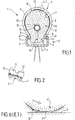
- figure 6 is a partial illustration, according to a sectional view, of the behavior of a wheel, according to the document FR 2,607,448 when pedaling.
- the wheel according to the document FR 2,607,448 comprises an outer casing 5 ', a rim (not shown), and a bandage 9' in a cellular closed-cell material.
- the tire 9 has a contact surface cooperating with the inner surface of said envelope, not bonded to this surface.
- the tire has a heel located between two lateral shoulders of the rim, said bead compressing two free edges of said outer casing, respectively, against said two lateral shoulders of said rim.
- the bandage 9 may optionally have a density between 0.15 and 0.40.
- the outer casing 5 may be elastomeric, at least partially, carved, having on its rolling surface 6 relief patterns.
- the outer envelope 5 may in particular be a commercial envelope.
- the two free edges 8 of the outer casing 9 may each have a reinforcement 17, in particular a metal frame, embedded in the elastomer material, in particular envelope.
- the two lateral shoulders 4 of the rim 2 may have ribs 41, facing one another, and intended to pick the free edges 8 of the envelope 5.
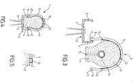
- said tire 9 has a contact surface 10 cooperating with the inner surface 7 of said outer envelope 5, and a heel 11, located between said two lateral shoulders 4.
- the heel 11 compresses said two free circular edges 8 of said outer casing 5, respectively, against said two lateral shoulders 4 of said rim, allowing the casing 9 / bandage assembly 9 to be held on the rim 2.
- the bandage 9 occupies at least 60% of preferably at least 70% of the volume between said outer casing 5 and said rim 2, allowing the use of the wheel 1 under particularly satisfactory conditions, even if the wheel does not have an inner tube, or in the case where said wheel has a tube, not inflated or punctured.
- the bandage 9 occupies at least 80% of the volume between said casing and the rim.
- the tire 9 occupies the entire available volume between said casing 5 and the rim 2.
- the wheel 1 has, in addition, means 12; 13 for securing the contact surface 10 of the tire 9 to said outer shell 5, avoiding or at least strongly limiting the creation of said bead B.
- the inventor has thus measured a sharp decrease in rolling resistance with a wheel according to the invention, in comparison with a wheel according to the document FR 2,607,448 .
- said means for securing said contact surface 10 of the tire 9 to said outer shell 5 are constituted by gluing means 12 such as glue, or a double-sided adhesive.
- gluing means 12 such as glue, or a double-sided adhesive.
- the contact surface 10 of the tire 9 is secured to the inner surface 7 of the envelope with glue.
- said means for securing said contact surface 10 of the tire 9 to said outer casing 5 are constituted by mechanical means.
- said mechanical means may consist of staples 13 passing through said outer shell 5 and said tire 9.
- these staples 13 may be located in the grooves of the sculpted tread surface 6 of the outer shell 5, such that the staples 13 are set back from the contact surface of the outer envelope 9.
- the wheel 1 can be without a tube.
- the tire may have an air chamber 14.
- the tire 9 then has a recess 15, internal, circular receiving said air chamber 14, and a slot 16 which extends from the surface of the heel 11, facing said core 3 of the rim 2, to the recess 15.
- This slot 16 allows, by deforming the bandage 9, to open the bandage and thus the insertion or removal of said air chamber 14 in said recess 15.
- This air chamber 14 has a valve (not shown) integral with said inner tube, intended to emerge through the core of the rim 2 through an orifice (not shown).
- the air chamber 14 has the sole function of obtaining a surplus of comfort. Because of the important place occupied by the tire 9, which occupies at least 60%, preferably at least 70%, or even 80% of the available volume between said outer casing 5 and the rim 2, the wheel 1 can be used so quite satisfactory, under normal conditions of use, even if the user forgets to inflate the tube 14.
- the material of the bandage 9 consists of at least 85% by weight of ethylene vinyl acetate.
- the formulated material is fed, after mechanical dosing, into a hopper for feeding an endless screw, housed in a sheath between 600 ° C. and 150 ° C.
- This material is compressed, kneaded and heated, producing a homogeneous paste which is pushed by the screw through a feed port of a mold.
- the dough is fired in the mold at a temperature between 150 ° C and 250 ° C.
- the mold is then opened to remove the piece, which in contact with the air solidifies, obtaining said bandage.
- the slot 16 and the recess 15 can be obtained during molding, or during a subsequent cutting step.
- the outer casing 5 is manufactured independently of the bandage 9.
- the independent manufacture of the bandage 9, on the one hand, and the outer casing 5, on the other hand allows an optimum manufacture of each of these two elements 5, 9, according to the constraints which are their own.
- the outer envelope 5 may be a commercial envelope, usually used with an inner tube to constitute a traditional wheel.
- the step of securing said contact surface 10 of the tire 9 to said outer casing 5 may be implemented, at least in part before the setting, by force, of the outer casing / bandage assembly on the rim, for example using glue, or, at a step following this implementation, for example by means of said staples 13.
- This tooling includes a turntable and pressure rollers actuated by cylinders.
- the tire 9 is manually inserted into the outer envelope 5, then one of the free circular edges 8 of the outer envelope 5 is inserted between the two lateral shoulders 4 of the rim 2 ( figure 3 ).
- the wheel is then fixed on the turntable.
- the pressure rollers of the tooling during the rotation of the wheel, forcing the other free edge 8 of the outer casing 5 between the two shoulders 4 of the rim 2 by compressing the heel 11 bandage 9.
Landscapes
- Engineering & Computer Science (AREA)
- Mechanical Engineering (AREA)
- Tires In General (AREA)
Applications Claiming Priority (1)
| Application Number | Priority Date | Filing Date | Title |
|---|---|---|---|
| FR1100913A FR2973283A1 (fr) | 2011-03-28 | 2011-03-28 | Bandage anti-crevaison mini-chambre |
Publications (1)
| Publication Number | Publication Date |
|---|---|
| EP2505385A1 true EP2505385A1 (de) | 2012-10-03 |
Family
ID=44343910
Family Applications (1)
| Application Number | Title | Priority Date | Filing Date |
|---|---|---|---|
| EP12160587A Withdrawn EP2505385A1 (de) | 2011-03-28 | 2012-03-21 | Pannensicheres Rad für ein Fahrrad |
Country Status (2)
| Country | Link |
|---|---|
| EP (1) | EP2505385A1 (de) |
| FR (1) | FR2973283A1 (de) |
Citations (8)
| Publication number | Priority date | Publication date | Assignee | Title |
|---|---|---|---|---|
| FR2013313A1 (en) * | 1968-07-19 | 1970-03-27 | Krispis Constantinos | Safety tyre |
| FR2249781A1 (en) * | 1973-11-02 | 1975-05-30 | Basf Ag | Tubeless safety tyre for automobiles - partly filled with closed-cell foamed profile of partly crystalline olefin polymer |
| FR2310230A1 (fr) | 1975-05-06 | 1976-12-03 | Goodyear Tire & Rubber | Bandage moule et son procede de fabrication |
| FR2607448A1 (fr) | 1986-11-28 | 1988-06-03 | Maillard Maurice Ets | Bandages pour roues de vehicules legers, notamment de cycles |
| FR2639880A1 (fr) | 1988-12-01 | 1990-06-08 | Hutchinson | Garniture annulaire pour pneumatique, en particulier de cycle ou de motocycle, et pneumatique comprenant cette garniture |
| FR2755400A1 (fr) | 1996-11-07 | 1998-05-07 | Hutchinson | Chambre a air ayant une resistance aux crevaisons renforcee et son procede de fabrication |
| EP0940269A2 (de) * | 1998-03-04 | 1999-09-08 | Sumitomo Rubber Industries Ltd. | Reifensystem für motoräder |
| EP1980421A1 (de) * | 2007-04-13 | 2008-10-15 | Solideal Holding Sa | Einsatz zur Montage in einen aufblasbaren Reifen |
-
2011
- 2011-03-28 FR FR1100913A patent/FR2973283A1/fr active Pending
-
2012
- 2012-03-21 EP EP12160587A patent/EP2505385A1/de not_active Withdrawn
Patent Citations (8)
| Publication number | Priority date | Publication date | Assignee | Title |
|---|---|---|---|---|
| FR2013313A1 (en) * | 1968-07-19 | 1970-03-27 | Krispis Constantinos | Safety tyre |
| FR2249781A1 (en) * | 1973-11-02 | 1975-05-30 | Basf Ag | Tubeless safety tyre for automobiles - partly filled with closed-cell foamed profile of partly crystalline olefin polymer |
| FR2310230A1 (fr) | 1975-05-06 | 1976-12-03 | Goodyear Tire & Rubber | Bandage moule et son procede de fabrication |
| FR2607448A1 (fr) | 1986-11-28 | 1988-06-03 | Maillard Maurice Ets | Bandages pour roues de vehicules legers, notamment de cycles |
| FR2639880A1 (fr) | 1988-12-01 | 1990-06-08 | Hutchinson | Garniture annulaire pour pneumatique, en particulier de cycle ou de motocycle, et pneumatique comprenant cette garniture |
| FR2755400A1 (fr) | 1996-11-07 | 1998-05-07 | Hutchinson | Chambre a air ayant une resistance aux crevaisons renforcee et son procede de fabrication |
| EP0940269A2 (de) * | 1998-03-04 | 1999-09-08 | Sumitomo Rubber Industries Ltd. | Reifensystem für motoräder |
| EP1980421A1 (de) * | 2007-04-13 | 2008-10-15 | Solideal Holding Sa | Einsatz zur Montage in einen aufblasbaren Reifen |
Also Published As
| Publication number | Publication date |
|---|---|
| FR2973283A1 (fr) | 2012-10-05 |
Similar Documents
| Publication | Publication Date | Title |
|---|---|---|
| EP2379317B1 (de) | Auskleidungsanordnung auf einer haut einer reifenvulkanisierungsform | |
| EP2277717A2 (de) | Abdeckring zwischen Felge und Reifen eines Fahrradrades und mit einem solchen Abdeckring ausgestattetes Fahrradrad | |
| EP3079891B1 (de) | Formteil-zusammenstellung für den einsatz in einem formwerkzeug | |
| EP3393748B1 (de) | Verfahren zum coextrudieren eines komplexen kautschukprofils zur herstellung eines reifens | |
| EP3094503A1 (de) | Verbesserte lauffläche für einen reifen | |
| EP1485262B1 (de) | Rad mit felge aus verbundwerkstoff hergestellt durch rtm- verfahren | |
| EP0665098B1 (de) | Luftreifen | |
| FR2973283A1 (fr) | Bandage anti-crevaison mini-chambre | |
| WO2001089861A1 (fr) | Pneumatique comprenant un profile de renfort dans au moins un flanc, et ensemble monte pneumatique/jante | |
| EP3642113B1 (de) | Vorrichtung zur akustischen behandlung einer triebwerksgondel eines flugzeuges | |
| EP3370936A1 (de) | Verfahren und form zur erzeugung eines aerodynamischen elements mit rippen | |
| EP4117899A1 (de) | Auskleidungselement einer vulkanisierform für einen reifen mit lamellen | |
| EP1682363B1 (de) | Segmentierte stütze | |
| EP2459404B1 (de) | Gelenkglastafel mit kammförmigem einsatz sowie verfahren zur herstellung dieser glastafel | |
| EP3233456B1 (de) | Form und verfahren zum vulkanisieren eines ringförmigen adapters für eine reifenfelge | |
| FR2855440A1 (fr) | Procede de fabrication d'une aube creuse pour turbomachine. | |
| EP2825399B1 (de) | Dicke lauffläche für reifen ziviler baufahrzeuge | |
| EP3681737B1 (de) | Form für eine reifenlauffläche mit verdeckten kanälen | |
| EP3155943A1 (de) | Verfahren zur herstellung einer duschwanne aus einer verbundplatte | |
| WO2020208575A1 (fr) | Bandage plein en matériau élastomère pour galet de roulement de telepherique | |
| FR2809348A1 (fr) | Pneumatique comprenant un profile de renfort dans au moins un flanc et ensemble pneumatique/jante comprenant un tel pneumatique | |
| FR2639880A1 (fr) | Garniture annulaire pour pneumatique, en particulier de cycle ou de motocycle, et pneumatique comprenant cette garniture | |
| FR3086847A1 (fr) | Casque et son procede de fabrication | |
| EP3390028A1 (de) | Lamellen zum auskleiden einer reifenform und zugehöriges herstellungsverfahren | |
| FR2997900A1 (fr) | Pneu ayant des flancs reduisant la trainee aerodynamique |
Legal Events
| Date | Code | Title | Description |
|---|---|---|---|
| PUAI | Public reference made under article 153(3) epc to a published international application that has entered the european phase |
Free format text: ORIGINAL CODE: 0009012 |
|
| AK | Designated contracting states |
Kind code of ref document: A1 Designated state(s): AL AT BE BG CH CY CZ DE DK EE ES FI FR GB GR HR HU IE IS IT LI LT LU LV MC MK MT NL NO PL PT RO RS SE SI SK SM TR |
|
| AX | Request for extension of the european patent |
Extension state: BA ME |
|
| STAA | Information on the status of an ep patent application or granted ep patent |
Free format text: STATUS: THE APPLICATION IS DEEMED TO BE WITHDRAWN |
|
| 18D | Application deemed to be withdrawn |
Effective date: 20130404 |