EP2505389B1 - Pneus de véhicule - Google Patents
Pneus de véhicule Download PDFInfo
- Publication number
- EP2505389B1 EP2505389B1 EP20120153973 EP12153973A EP2505389B1 EP 2505389 B1 EP2505389 B1 EP 2505389B1 EP 20120153973 EP20120153973 EP 20120153973 EP 12153973 A EP12153973 A EP 12153973A EP 2505389 B1 EP2505389 B1 EP 2505389B1
- Authority
- EP
- European Patent Office
- Prior art keywords
- sipes
- profile
- pairs
- depth
- pneumatic vehicle
- Prior art date
- Legal status (The legal status is an assumption and is not a legal conclusion. Google has not performed a legal analysis and makes no representation as to the accuracy of the status listed.)
- Not-in-force
Links
Images


Classifications
-
- B—PERFORMING OPERATIONS; TRANSPORTING
- B60—VEHICLES IN GENERAL
- B60C—VEHICLE TYRES; TYRE INFLATION; TYRE CHANGING; CONNECTING VALVES TO INFLATABLE ELASTIC BODIES IN GENERAL; DEVICES OR ARRANGEMENTS RELATED TO TYRES
- B60C11/00—Tyre tread bands; Tread patterns; Anti-skid inserts
- B60C11/03—Tread patterns
- B60C11/12—Tread patterns characterised by the use of narrow slits or incisions, e.g. sipes
- B60C11/1259—Depth of the sipe
- B60C11/1263—Depth of the sipe different within the same sipe
-
- B—PERFORMING OPERATIONS; TRANSPORTING
- B60—VEHICLES IN GENERAL
- B60C—VEHICLE TYRES; TYRE INFLATION; TYRE CHANGING; CONNECTING VALVES TO INFLATABLE ELASTIC BODIES IN GENERAL; DEVICES OR ARRANGEMENTS RELATED TO TYRES
- B60C11/00—Tyre tread bands; Tread patterns; Anti-skid inserts
- B60C11/03—Tread patterns
- B60C11/0306—Patterns comprising block rows or discontinuous ribs
-
- B—PERFORMING OPERATIONS; TRANSPORTING
- B60—VEHICLES IN GENERAL
- B60C—VEHICLE TYRES; TYRE INFLATION; TYRE CHANGING; CONNECTING VALVES TO INFLATABLE ELASTIC BODIES IN GENERAL; DEVICES OR ARRANGEMENTS RELATED TO TYRES
- B60C11/00—Tyre tread bands; Tread patterns; Anti-skid inserts
- B60C11/03—Tread patterns
- B60C11/12—Tread patterns characterised by the use of narrow slits or incisions, e.g. sipes
- B60C11/1236—Tread patterns characterised by the use of narrow slits or incisions, e.g. sipes with special arrangements in the tread pattern
-
- B—PERFORMING OPERATIONS; TRANSPORTING
- B60—VEHICLES IN GENERAL
- B60C—VEHICLE TYRES; TYRE INFLATION; TYRE CHANGING; CONNECTING VALVES TO INFLATABLE ELASTIC BODIES IN GENERAL; DEVICES OR ARRANGEMENTS RELATED TO TYRES
- B60C11/00—Tyre tread bands; Tread patterns; Anti-skid inserts
- B60C11/03—Tread patterns
- B60C2011/0337—Tread patterns characterised by particular design features of the pattern
- B60C2011/0386—Continuous ribs
- B60C2011/0388—Continuous ribs provided at the equatorial plane
-
- B—PERFORMING OPERATIONS; TRANSPORTING
- B60—VEHICLES IN GENERAL
- B60C—VEHICLE TYRES; TYRE INFLATION; TYRE CHANGING; CONNECTING VALVES TO INFLATABLE ELASTIC BODIES IN GENERAL; DEVICES OR ARRANGEMENTS RELATED TO TYRES
- B60C11/00—Tyre tread bands; Tread patterns; Anti-skid inserts
- B60C11/03—Tread patterns
- B60C11/12—Tread patterns characterised by the use of narrow slits or incisions, e.g. sipes
- B60C2011/129—Sipe density, i.e. the distance between the sipes within the pattern
-
- B—PERFORMING OPERATIONS; TRANSPORTING
- B60—VEHICLES IN GENERAL
- B60C—VEHICLE TYRES; TYRE INFLATION; TYRE CHANGING; CONNECTING VALVES TO INFLATABLE ELASTIC BODIES IN GENERAL; DEVICES OR ARRANGEMENTS RELATED TO TYRES
- B60C11/00—Tyre tread bands; Tread patterns; Anti-skid inserts
- B60C11/03—Tread patterns
- B60C11/12—Tread patterns characterised by the use of narrow slits or incisions, e.g. sipes
- B60C2011/129—Sipe density, i.e. the distance between the sipes within the pattern
- B60C2011/1295—Sipe density, i.e. the distance between the sipes within the pattern variable
Definitions
- the invention relates to a pneumatic vehicle tire with a tread with circumferentially encircling and free of transverse grooves profile bands, which instead of transverse grooves parallel to each other and extending substantially in the tread transverse direction incisions having a width of 0.4 mm to 0.8 mm, with cuts are provided whose normal distance is 5 mm to 10 mm.
- profiled treads which are composed solely of profile block rows or profile bands or have a combination of profile block rows with Profilbändem.
- profile band is a circumferential circumferential, usually limited by circumferential grooves section in the tread understood, which has no transverse grooves passing through it.
- Both profiled strips and profiled block rows can, depending on the intended use of the tire, be provided with cuts, which usually have a width of 0.4 mm to 0.8 mm.
- the main purpose of cross grooves and cuts is to help drain the profile to prevent aquaplaning, to ensure tire traction on wet and dry surfaces, and to reduce rolling resistance.
- a pneumatic vehicle tire of the type mentioned is for example from the US 5,109,901 A known.
- This pneumatic vehicle tire has tread strips in the tread which do not contain any transverse grooves but are provided with a multiplicity of cuts running parallel to each other and substantially in the tread transverse direction. The mutual distance of the incisions is the same for all cuts and amounts to between 3 mm and 20 mm.
- the EP 1 864 830 A2 discloses a pneumatic vehicle tire having a tread with tread bands separated from one another by circumferentially straight peripheral grooves. Of the circumferential grooves protrude very short, mutually equally spaced incisions in the profile strips. An analogous measure is taken in profile bands of the tread, which from the US 4,459,560 A is known.
- the GB 2 160 829 A discloses a vehicle pneumatic tire having a tread with a number of profile bands in which are also formed parallel to each other incisions.
- the pitch of the sipes is changed according to a method of pitch length variation so that there are cuts in tread bands having smaller and other sipes having a larger mutual distance.
- a pneumatic vehicle tire the tread is composed of a number of profile block rows.
- the blocks in the tread block rows are separated from each other by transverse grooves and each have in pairs in tread transverse direction recesses, which are locally widened at their radially inner ends to prevent the formation of tears at the bottom of the incisions during demolding of the tire after vulcanization.
- a tire which has a tread pattern with rows of blocks. The blocks are each provided with two pairs of treads running in tread to improve the grip characteristics.
- the transverse grooves in treads of tires are of importance above all for good wet-setting properties and low rolling resistance, but they represent a clearly perceptible source of noise in the tire's rolling noise.
- the invention is based on the object in a tire of the type mentioned to improve or reduce the rolling noise, but to get good Nässeeigenschaften and to allow during rolling such a deformation of the tread that a low rolling resistance is guaranteed.
- the object is achieved according to the invention in that the incisions whose normal distance is 5 mm to 10 mm are arranged in pairs of cuts, wherein the mutual distance of the pairs of cuts, determined at the ends of the incisions as the distance of the facing incisions of the two pairs of cuts between 25 mm and 35 mm.
- a pneumatic vehicle tire constructed in accordance with the invention has a tread pattern with tread bands provided with paired incisions, the arrangement of which is aligned with the arrangement of conventional transverse grooves in tread block rows.
- the "profile mechanics" therefore essentially corresponds to that of a conventional tread pattern with transverse grooves.
- especially the drivewear properties of inventive treads correspond at least to those of a conventionally designed tread.
- the replacement of the transverse grooves by pairs of cuts causes a division of the rolling movement occurring during rolling in the circumferential direction of a joint point, as is the case with a transverse groove to two Joints. For the noise, this means a shift of the excitation frequency towards higher frequencies.
- an excitation frequency of the order of 800 Hz results at a driving speed of 80 km / h.
- Replacement of the transverse grooves by incision pairs reduces the excitation at 800 Hz and generates an additional excitation which is clearly above 800 Hz is. Since frequencies above 1000 Hz are emitted poorly in passenger car pneumatic tires, worse than frequencies below 1000 Hz, a pneumatic vehicle tire according to the invention with exported profile bands instead of profile block rows is significantly quieter.
- Profile strips which are largely structured only by incisions, also produce a much lower contact pressure than profile block rows, whereby the rubber material is compressed less in the tread.
- the mutual supporting effect of the incision walls is counteracted by the reduction of the compression. These effects are particularly positive for lower rolling resistance.
- the rubber material between the paired cuts stabilizes the tread when it is subjected to kinking and bending stresses across the tire width. This stabilization offers advantages in terms of tread wear and dry driving properties.
- the paired incisions are arranged in the profile band in two rows of incisions, which are preferably offset from one another in the circumferential direction. With such arranged pairs of cuts can be selectively taken influence on the contact pressure and the stability of the profile strip.
- An alternative embodiment, in which the paired incisions traverse the profile band, also allows a corresponding influence.
- connection grooves which are of the same width as the incisions but have a smaller depth than the incisions, in particular their depth is a few tenths of a millimeter up to 1 mm.
- Such compound grooves support the drainage in a new tire, but also have a decorative effect.
- These connection grooves can also run in the circumferential direction.
- the paired incisions or their sections extend at an acute angle of 3 ° to 10 ° to the tread transverse direction.
- the paired incisions have a certain minimum depth. Their depth should either correspond to the tread depth or by up to 5 mm, in particular by up to 3 mm, be less than the tread depth.
- the profile band between pairs of incisions is provided at least on one side with indentations or pockets.
- the profile element bridge between the paired cuts against the present at this point profile bandwidth in the transverse direction is somewhat shortened.
- edge portions are provided on the tread bands in the transverse direction, which support the traction of the tire, for example in slush or snow.
- the pockets extend to an extent of 1 mm to 3 mm in the profile band and extend in the radial direction at most up to the tread depth or the depth of the respective profile band limiting (n) circumferential groove or circumferential grooves.
- Fig. 1 to Fig. 5 show different embodiments of profile bands 1 for a tread for a pneumatic vehicle tire in radial design, especially for passenger cars, vans and the like.
- executed pneumatic vehicle tires have treads which comprise at least one profile strip according to the invention carried out, but in particular consist predominantly or exclusively of profile bands according to the invention.
- Tread with inventively designed profile bands may also have differently executed profile bands or profile block rows.
- the tread on between three and five executed according to the invention profile strips.
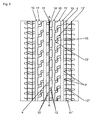
- Fig. 6 shows a preferred embodiment of the invention with five profile bands.
- FIGS. 1 to 5 show variants of profile strips 1, which in the circumferential direction on both sides have profile band edges 1a, which limit circumferential grooves 10.
- the circumferential grooves 10 are shown as straight grooves, but can also extend in the circumferential direction in a wave or zigzag shape, depending on the course of the profile band edges 1a.
- An essential feature of the invention is the structuring of the profile strips 1 with pairs and parallel to each other arranged incisions 2, 2 ', 2 " Distance a of the incision pairs, which at the ends of the incisions 2, 2 ', 2 "on a profile band edge 1a and between the two facing incisions 2, 2', 2" of two circumferentially adjoining incision pairs 2, 2 ', 2 " is determined, is between 25 mm and 35 mm and therefore corresponds to the usual circumferential extent of profile blocks in profile block rows.
- the mutual normal distance b of the paired incisions 2, 2 ', 2 substantially corresponds to the width of the profiled element bridge 3 between the incisions 2, 2', 2" and is between 5 mm and 10 mm.
- the distance b thus corresponds to the usual width of grooves in profile block rows.
- the distance b remains substantially constant over the extent or the course of the paired incisions 2, 2 ', 2 "The incisions 2, 2', 2" themselves have a width in the order of 0.4 mm to 0.8 mm, in particular about 0.6 mm.
- the depth of the cuts 2, 2 ', 2 “corresponds to the intended tread depth, which is usually 8 mm, or is up to 5 mm, in particular up to 3 mm, less than the tread depth.
- the paired incisions 2 run straight in the tread transverse direction and traverse the profile band 1 Fig. 2 the embodiment shown corresponds to the course of the incisions 2 that of in Fig. 1 shown embodiment.
- the profile band 1 is provided on the profile band flanks 1a between the paired incisions 2 with indentations or pockets 4, so that the extension of the profile element bridges 3 in tread transverse direction is less than the width of the profile band 1 at this point.
- the pockets 4 extend between 1 mm and 3 mm in the profile band 1 and extend in the radial direction at most up to the tread depth or the depth of the circumferential grooves 10th
- Fig. 3 shows a variant in which the paired incisions 2 'the profiled strip edges 1a adjacent initially each running in the tread transverse direction incision sections 2'a have, which via incision sections 2'b, which extend at an acute angle to the tread transverse direction, interconnected are and are offset from each other in the circumferential direction.
- the transition areas between the individual cut-in sections 2'a and 2'b are rounded.
- the cut-in portions 2'b, with or without the subsequent rounded transitions, may have a depth which either corresponds to the depth of the cut-in portions 2'a or is somewhat smaller, in particular by up to 2 mm.
- connection grooves with a depth of a few tenths of a millimeter up to 1 mm may be provided, which merely have a decorative function.
- FIG. 3 embodiment shown are also analogous to the embodiment according to Fig. 2 Pockets 4 provided.
- paired incisions 2 are provided in the profile band 1.
- the paired incisions 2" terminate in the profile band center and run opposite the tread transverse direction at an acute angle which does not exceed 45 °.
- the incisions 2 have at their ends bent short sections 2" c, which are preferably made very shallow and in particular have a depth of a few tenths of a millimeter up to 1 mm.
- pockets 4 are provided.
- Fig. 5 shows an embodiment which is a variant of in Fig. 3 shown embodiment.
- the paired incisions 2 'therefore have incision sections 2'a and 2'b.
- the profile band flanks are 1a, as it is Fig. 5a shows, chamfered directly to the profile surface in a known manner, so that they have short inclined surfaces 5.
- the paired incisions 2, 2 ', 2 "replace the transverse grooves usually provided in the profile block rows between the tread blocks
- the paired incisions 2, 2', 2" effect a distribution of the bending movements of the tread circumferentially during the unwinding of the tread Tire from a "joint” - in transverse grooves - on two “joints".
- the excitation frequency is on the order of 800 Hz.
- a pneumatic vehicle tire which is designed according to the invention, is significantly quieter than a tire with a block profile with transverse grooves.
- Fig. 1b shows schematically the deformation of a pair of cuts during the rolling of the tire just before entering or shortly after exiting the lat.
- Fig. 6 shows a partial development of a variant of a running according to the invention profiled tread.
- the tread shown has five circumferentially encircling tread bands 11, 11 'and 11 "along the tire equator, which is indicated by the line AA, runs the tread band 11, which with two rows of paired incisions 12 which offset in the circumferential direction against each other
- the design of the recess pairs with pockets 4 is essentially analogous to Fig. 4 with the difference that the cuts 12 have no shallow end portions.
- the incisions 12 are all parallel to each other and are inclined with respect to the tread transverse direction at a small acute angle of the order of 3 ° to 10 °.
- the profile band 11 is formed by two wide, circumferentially straight circumferential grooves 10 of the profile bands 11' separated, which in turn are separated by further, straight and circumferentially circumferential grooves 10 of the shoulder-side profile strips 11 "
- the incisions 12 form two rows of circumferentially offset pairs of incisions according to the invention.
- Connecting grooves 15 whose width corresponds to the incision width and which have a very small depth of a few tenths of a millimeter to 1 mm and extend in the circumferential direction, connect the notches 12 '. Also in the profile strips 11 'are located at the profile strip edges between the pairwise related cuts 12' the described pockets. 4
Landscapes
- Engineering & Computer Science (AREA)
- Mechanical Engineering (AREA)
- Tires In General (AREA)
Claims (11)
- Pneumatique de véhicule comprenant une bande de roulement avec des bandes profilées (1, 11, 11', 11'') s'étendant circonférentiellement dans la direction périphérique et exemptes de rainures transversales, qui présentent, au lieu de rainures transversales, des entailles (2, 2', 2 " , 12, 12', 12") parallèles les unes aux autres et s'étendant essentiellement dans la direction transversale de la bande de roulement, avec une largeur de 0,4 mm à 0,8 mm, des entailles (2, 2', 2", 12, 12', 12") étant prévues, dont la distance normale est de 5 mm à 10 mm,
caractérisé en ce que
les entailles (2, 2', 2", 12, 12', 12") dont la distance normale est de 5 mm à 10 mm sont disposées par paires d'entailles, la distance mutuelle (a) des paires d'entailles, aux extrémités des entailles (2, 2', 2", 12, 12', 12"), déterminée en tant que distance des entailles tournées l'une vers l'autre (2, 2', 2", 12, 12', 12") des deux paires d'entailles, étant comprise entre 25 mm et 35 mm. - Pneumatique de véhicule selon la revendication 1, caractérisé en ce que les entailles disposées par paires (2", 12') sont disposées dans la bande profilée (1, 11') en deux rangées d'entailles qui sont de préférence décalées dans une direction périphérique les unes par rapport aux autres.
- Pneumatique de véhicule selon la revendication 2, caractérisé en ce qu'à chaque fois deux paires d'entailles adjacentes dans la direction périphérique, provenant des deux rangées d'entailles, sont connectées l'une à l'autre par des gorges de connexion (15) qui ont la même largeur que les entailles (12') et présentent une plus faible profondeur que les entailles (12').
- Pneumatique de véhicule selon la revendication 3, caractérisé en ce que les gorges de connexion (15) présentent une profondeur de quelques dixièmes de millimètre jusqu'à un millimètre.
- Pneumatique de véhicule selon la revendication 1, caractérisé en ce que les entailles disposées par paires (2, 2') traversent la bande profilée (1).
- Pneumatique de véhicule selon la revendication 1 ou 5, caractérisé en ce que les entailles disposées par paires (2'), de manière adjacente aux flancs de bande profilée (la), présentent des portions d'entailles (2'a) qui sont décalées les unes par rapport aux autres dans la direction périphérique et qui sont connectées par le biais de portions d'entailles centrales (2'b) qui s'étendent suivant un plus grand angle aigu par rapport à la direction transversale de la bande de roulement que les portions d'entailles (2'a) au niveau des flancs de bande profilée (la).
- Pneumatique de véhicule selon la revendication 6, caractérisé en ce que les portions d'entailles centrales (2'b) présentent une profondeur qui correspond à la profondeur des portions d'entailles (2'a) s'y raccordant ou est inférieure de jusqu'à 2 mm à la profondeur des portions d'entailles (2'a) s'y raccordant.
- Pneumatique de véhicule selon l'une quelconque des revendications 1 à 7, caractérisé en ce que les entailles disposées par paires (2, 2', 2", 12, 12', 12") s'étendent suivant un angle aigu compris entre 3° et 10° par rapport à la direction transversale de la bande de roulement.
- Pneumatique de véhicule selon l'une quelconque des revendications 1 à 8, caractérisé en ce que les entailles disposées par paires (2, 2', 2", 12, 12', 12") présentent une profondeur qui correspond à la profondeur du profilé ou qui est inférieure à la profondeur du profilé de jusqu'à 5 mm, en particulier de jusqu'à 3 mm.
- Pneumatique de véhicule selon l'une quelconque des revendications 1 à 9, caractérisé en ce que la bande profilée (1) est pourvue au moins d'un côté de renfoncements ou de cavités (4) entre des entailles disposées par paires (2, 2', 2", 12, 12', 12").
- Pneumatique de véhicule selon la revendication 10, caractérisé en ce que les cavités (4) pénètrent sur entre 1 mm et 3 mm dans la bande profilée (1, 11, 11') et s'étendent dans la direction radiale au maximum jusqu'à la profondeur du profilé.
Priority Applications (1)
| Application Number | Priority Date | Filing Date | Title |
|---|---|---|---|
| PL12153973T PL2505389T3 (pl) | 2011-03-29 | 2012-02-06 | Opona pneumatyczna do pojazdu |
Applications Claiming Priority (1)
| Application Number | Priority Date | Filing Date | Title |
|---|---|---|---|
| DE102011001634A DE102011001634A1 (de) | 2011-03-29 | 2011-03-29 | Fahrzeugluftreifen |
Publications (2)
| Publication Number | Publication Date |
|---|---|
| EP2505389A1 EP2505389A1 (fr) | 2012-10-03 |
| EP2505389B1 true EP2505389B1 (fr) | 2015-04-29 |
Family
ID=45560798
Family Applications (1)
| Application Number | Title | Priority Date | Filing Date |
|---|---|---|---|
| EP20120153973 Not-in-force EP2505389B1 (fr) | 2011-03-29 | 2012-02-06 | Pneus de véhicule |
Country Status (3)
| Country | Link |
|---|---|
| EP (1) | EP2505389B1 (fr) |
| DE (1) | DE102011001634A1 (fr) |
| PL (1) | PL2505389T3 (fr) |
Family Cites Families (9)
| Publication number | Priority date | Publication date | Assignee | Title |
|---|---|---|---|---|
| NL133932C (fr) * | 1967-09-18 | |||
| US4449560A (en) * | 1981-05-13 | 1984-05-22 | Bridgestone Tire Company Limited | Heavy duty pneumatic tire |
| JPS60240507A (ja) * | 1984-05-15 | 1985-11-29 | Sumitomo Rubber Ind Ltd | 低騒音マルチサイピングタイヤ |
| JPS6192902A (ja) * | 1984-10-13 | 1986-05-10 | Sumitomo Rubber Ind Ltd | 重荷重用空気入りラジアルタイヤ |
| JPS63279905A (ja) * | 1987-05-11 | 1988-11-17 | Bridgestone Corp | 空気入りラジアルタイヤ |
| ES2092060T3 (es) | 1991-11-01 | 1996-11-16 | Bridgestone Corp | Neumatico, molde y procedimiento para la fabricacion del mismo. |
| JP4899650B2 (ja) * | 2006-06-07 | 2012-03-21 | 横浜ゴム株式会社 | 空気入りタイヤ |
| JP4881697B2 (ja) | 2006-11-08 | 2012-02-22 | 株式会社ブリヂストン | 空気入りタイヤ |
| DE102010016508A1 (de) * | 2010-04-19 | 2011-10-20 | Continental Reifen Deutschland Gmbh | Fahrzeugluftreifen |
-
2011
- 2011-03-29 DE DE102011001634A patent/DE102011001634A1/de not_active Withdrawn
-
2012
- 2012-02-06 EP EP20120153973 patent/EP2505389B1/fr not_active Not-in-force
- 2012-02-06 PL PL12153973T patent/PL2505389T3/pl unknown
Also Published As
| Publication number | Publication date |
|---|---|
| EP2505389A1 (fr) | 2012-10-03 |
| DE102011001634A1 (de) | 2012-10-04 |
| PL2505389T3 (pl) | 2015-09-30 |
Similar Documents
| Publication | Publication Date | Title |
|---|---|---|
| EP2965925B1 (fr) | Pneumatiques de véhicule | |
| EP3383669B1 (fr) | Pneumatique de véhicule | |
| DE102005042569A1 (de) | Fahrzeugluftreifen | |
| EP1106393B1 (fr) | Bandage pneumatique pour véhicule | |
| EP4577416A1 (fr) | Pneu de véhicule | |
| EP3441241B1 (fr) | Pneumatique de véhicule | |
| EP3659825A1 (fr) | Pneumatique | |
| EP3551477B1 (fr) | Pneumatique de véhicule | |
| DE19957914A1 (de) | Fahrzeugluftreifen | |
| AT394002B (de) | Radialreifen fuer raeder von lkw-antriebsachsen | |
| EP4144542B1 (fr) | Pneumatique de véhicule | |
| EP4347276B1 (fr) | Pneu pour véhicule | |
| EP2000329B1 (fr) | Bandages pneumatiques | |
| EP4244079B1 (fr) | Pneumatique de véhicule | |
| EP2505389B1 (fr) | Pneus de véhicule | |
| DE102018206902A1 (de) | Fahrzeugluftreifen | |
| WO2018103920A1 (fr) | Pneumatique de véhicule | |
| EP4434768B1 (fr) | Bandage pneumatique pour véhicule | |
| EP1535759B1 (fr) | Bandage pneumatique | |
| EP4385761B1 (fr) | Bandage pneumatique pour véhicule | |
| EP1974956B1 (fr) | Pneus de véhicule | |
| EP3415344B1 (fr) | Pneumatique de véhicule | |
| EP3310592B1 (fr) | Pneumatique de véhicule | |
| EP4624201A1 (fr) | Bandage pneumatique pour véhicules | |
| EP3277524A1 (fr) | Pneumatique de véhicule |
Legal Events
| Date | Code | Title | Description |
|---|---|---|---|
| PUAI | Public reference made under article 153(3) epc to a published international application that has entered the european phase |
Free format text: ORIGINAL CODE: 0009012 |
|
| AK | Designated contracting states |
Kind code of ref document: A1 Designated state(s): AL AT BE BG CH CY CZ DE DK EE ES FI FR GB GR HR HU IE IS IT LI LT LU LV MC MK MT NL NO PL PT RO RS SE SI SK SM TR |
|
| AX | Request for extension of the european patent |
Extension state: BA ME |
|
| 17P | Request for examination filed |
Effective date: 20130403 |
|
| 17Q | First examination report despatched |
Effective date: 20140226 |
|
| GRAP | Despatch of communication of intention to grant a patent |
Free format text: ORIGINAL CODE: EPIDOSNIGR1 |
|
| INTG | Intention to grant announced |
Effective date: 20141127 |
|
| GRAP | Despatch of communication of intention to grant a patent |
Free format text: ORIGINAL CODE: EPIDOSNIGR1 |
|
| GRAS | Grant fee paid |
Free format text: ORIGINAL CODE: EPIDOSNIGR3 |
|
| GRAA | (expected) grant |
Free format text: ORIGINAL CODE: 0009210 |
|
| INTG | Intention to grant announced |
Effective date: 20150312 |
|
| AK | Designated contracting states |
Kind code of ref document: B1 Designated state(s): AL AT BE BG CH CY CZ DE DK EE ES FI FR GB GR HR HU IE IS IT LI LT LU LV MC MK MT NL NO PL PT RO RS SE SI SK SM TR |
|
| REG | Reference to a national code |
Ref country code: GB Ref legal event code: FG4D Free format text: NOT ENGLISH |
|
| REG | Reference to a national code |
Ref country code: CH Ref legal event code: EP |
|
| REG | Reference to a national code |
Ref country code: AT Ref legal event code: REF Ref document number: 724216 Country of ref document: AT Kind code of ref document: T Effective date: 20150515 |
|
| REG | Reference to a national code |
Ref country code: IE Ref legal event code: FG4D Free format text: LANGUAGE OF EP DOCUMENT: GERMAN |
|
| REG | Reference to a national code |
Ref country code: DE Ref legal event code: R096 Ref document number: 502012002961 Country of ref document: DE Effective date: 20150611 |
|
| REG | Reference to a national code |
Ref country code: NL Ref legal event code: T3 |
|
| REG | Reference to a national code |
Ref country code: LT Ref legal event code: MG4D |
|
| REG | Reference to a national code |
Ref country code: PL Ref legal event code: T3 |
|
| PG25 | Lapsed in a contracting state [announced via postgrant information from national office to epo] |
Ref country code: FI Free format text: LAPSE BECAUSE OF FAILURE TO SUBMIT A TRANSLATION OF THE DESCRIPTION OR TO PAY THE FEE WITHIN THE PRESCRIBED TIME-LIMIT Effective date: 20150429 Ref country code: LT Free format text: LAPSE BECAUSE OF FAILURE TO SUBMIT A TRANSLATION OF THE DESCRIPTION OR TO PAY THE FEE WITHIN THE PRESCRIBED TIME-LIMIT Effective date: 20150429 Ref country code: HR Free format text: LAPSE BECAUSE OF FAILURE TO SUBMIT A TRANSLATION OF THE DESCRIPTION OR TO PAY THE FEE WITHIN THE PRESCRIBED TIME-LIMIT Effective date: 20150429 Ref country code: NO Free format text: LAPSE BECAUSE OF FAILURE TO SUBMIT A TRANSLATION OF THE DESCRIPTION OR TO PAY THE FEE WITHIN THE PRESCRIBED TIME-LIMIT Effective date: 20150729 Ref country code: ES Free format text: LAPSE BECAUSE OF FAILURE TO SUBMIT A TRANSLATION OF THE DESCRIPTION OR TO PAY THE FEE WITHIN THE PRESCRIBED TIME-LIMIT Effective date: 20150429 Ref country code: PT Free format text: LAPSE BECAUSE OF FAILURE TO SUBMIT A TRANSLATION OF THE DESCRIPTION OR TO PAY THE FEE WITHIN THE PRESCRIBED TIME-LIMIT Effective date: 20150831 |
|
| PG25 | Lapsed in a contracting state [announced via postgrant information from national office to epo] |
Ref country code: GR Free format text: LAPSE BECAUSE OF FAILURE TO SUBMIT A TRANSLATION OF THE DESCRIPTION OR TO PAY THE FEE WITHIN THE PRESCRIBED TIME-LIMIT Effective date: 20150730 Ref country code: IS Free format text: LAPSE BECAUSE OF FAILURE TO SUBMIT A TRANSLATION OF THE DESCRIPTION OR TO PAY THE FEE WITHIN THE PRESCRIBED TIME-LIMIT Effective date: 20150829 Ref country code: RS Free format text: LAPSE BECAUSE OF FAILURE TO SUBMIT A TRANSLATION OF THE DESCRIPTION OR TO PAY THE FEE WITHIN THE PRESCRIBED TIME-LIMIT Effective date: 20150429 Ref country code: LV Free format text: LAPSE BECAUSE OF FAILURE TO SUBMIT A TRANSLATION OF THE DESCRIPTION OR TO PAY THE FEE WITHIN THE PRESCRIBED TIME-LIMIT Effective date: 20150429 |
|
| PG25 | Lapsed in a contracting state [announced via postgrant information from national office to epo] |
Ref country code: DK Free format text: LAPSE BECAUSE OF FAILURE TO SUBMIT A TRANSLATION OF THE DESCRIPTION OR TO PAY THE FEE WITHIN THE PRESCRIBED TIME-LIMIT Effective date: 20150429 Ref country code: EE Free format text: LAPSE BECAUSE OF FAILURE TO SUBMIT A TRANSLATION OF THE DESCRIPTION OR TO PAY THE FEE WITHIN THE PRESCRIBED TIME-LIMIT Effective date: 20150429 |
|
| REG | Reference to a national code |
Ref country code: DE Ref legal event code: R097 Ref document number: 502012002961 Country of ref document: DE |
|
| REG | Reference to a national code |
Ref country code: FR Ref legal event code: PLFP Year of fee payment: 5 |
|
| PG25 | Lapsed in a contracting state [announced via postgrant information from national office to epo] |
Ref country code: CZ Free format text: LAPSE BECAUSE OF FAILURE TO SUBMIT A TRANSLATION OF THE DESCRIPTION OR TO PAY THE FEE WITHIN THE PRESCRIBED TIME-LIMIT Effective date: 20150429 Ref country code: SK Free format text: LAPSE BECAUSE OF FAILURE TO SUBMIT A TRANSLATION OF THE DESCRIPTION OR TO PAY THE FEE WITHIN THE PRESCRIBED TIME-LIMIT Effective date: 20150429 Ref country code: RO Free format text: LAPSE BECAUSE OF NON-PAYMENT OF DUE FEES Effective date: 20150429 |
|
| PLBE | No opposition filed within time limit |
Free format text: ORIGINAL CODE: 0009261 |
|
| STAA | Information on the status of an ep patent application or granted ep patent |
Free format text: STATUS: NO OPPOSITION FILED WITHIN TIME LIMIT |
|
| 26N | No opposition filed |
Effective date: 20160201 |
|
| PG25 | Lapsed in a contracting state [announced via postgrant information from national office to epo] |
Ref country code: BE Free format text: LAPSE BECAUSE OF NON-PAYMENT OF DUE FEES Effective date: 20160229 Ref country code: SI Free format text: LAPSE BECAUSE OF FAILURE TO SUBMIT A TRANSLATION OF THE DESCRIPTION OR TO PAY THE FEE WITHIN THE PRESCRIBED TIME-LIMIT Effective date: 20150429 |
|
| PG25 | Lapsed in a contracting state [announced via postgrant information from national office to epo] |
Ref country code: MC Free format text: LAPSE BECAUSE OF FAILURE TO SUBMIT A TRANSLATION OF THE DESCRIPTION OR TO PAY THE FEE WITHIN THE PRESCRIBED TIME-LIMIT Effective date: 20150429 Ref country code: LU Free format text: LAPSE BECAUSE OF FAILURE TO SUBMIT A TRANSLATION OF THE DESCRIPTION OR TO PAY THE FEE WITHIN THE PRESCRIBED TIME-LIMIT Effective date: 20160206 |
|
| REG | Reference to a national code |
Ref country code: CH Ref legal event code: PL |
|
| GBPC | Gb: european patent ceased through non-payment of renewal fee |
Effective date: 20160206 |
|
| PG25 | Lapsed in a contracting state [announced via postgrant information from national office to epo] |
Ref country code: LI Free format text: LAPSE BECAUSE OF NON-PAYMENT OF DUE FEES Effective date: 20160229 Ref country code: CH Free format text: LAPSE BECAUSE OF NON-PAYMENT OF DUE FEES Effective date: 20160229 |
|
| REG | Reference to a national code |
Ref country code: IE Ref legal event code: MM4A |
|
| PG25 | Lapsed in a contracting state [announced via postgrant information from national office to epo] |
Ref country code: IE Free format text: LAPSE BECAUSE OF NON-PAYMENT OF DUE FEES Effective date: 20160206 Ref country code: GB Free format text: LAPSE BECAUSE OF NON-PAYMENT OF DUE FEES Effective date: 20160206 |
|
| REG | Reference to a national code |
Ref country code: FR Ref legal event code: PLFP Year of fee payment: 6 |
|
| PG25 | Lapsed in a contracting state [announced via postgrant information from national office to epo] |
Ref country code: SE Free format text: LAPSE BECAUSE OF FAILURE TO SUBMIT A TRANSLATION OF THE DESCRIPTION OR TO PAY THE FEE WITHIN THE PRESCRIBED TIME-LIMIT Effective date: 20150429 |
|
| PG25 | Lapsed in a contracting state [announced via postgrant information from national office to epo] |
Ref country code: MT Free format text: LAPSE BECAUSE OF FAILURE TO SUBMIT A TRANSLATION OF THE DESCRIPTION OR TO PAY THE FEE WITHIN THE PRESCRIBED TIME-LIMIT Effective date: 20150429 |
|
| REG | Reference to a national code |
Ref country code: FR Ref legal event code: PLFP Year of fee payment: 7 |
|
| REG | Reference to a national code |
Ref country code: AT Ref legal event code: MM01 Ref document number: 724216 Country of ref document: AT Kind code of ref document: T Effective date: 20170206 |
|
| PG25 | Lapsed in a contracting state [announced via postgrant information from national office to epo] |
Ref country code: SM Free format text: LAPSE BECAUSE OF FAILURE TO SUBMIT A TRANSLATION OF THE DESCRIPTION OR TO PAY THE FEE WITHIN THE PRESCRIBED TIME-LIMIT Effective date: 20150429 Ref country code: HU Free format text: LAPSE BECAUSE OF FAILURE TO SUBMIT A TRANSLATION OF THE DESCRIPTION OR TO PAY THE FEE WITHIN THE PRESCRIBED TIME-LIMIT; INVALID AB INITIO Effective date: 20120206 Ref country code: AT Free format text: LAPSE BECAUSE OF NON-PAYMENT OF DUE FEES Effective date: 20170206 Ref country code: CY Free format text: LAPSE BECAUSE OF FAILURE TO SUBMIT A TRANSLATION OF THE DESCRIPTION OR TO PAY THE FEE WITHIN THE PRESCRIBED TIME-LIMIT Effective date: 20150429 |
|
| PG25 | Lapsed in a contracting state [announced via postgrant information from national office to epo] |
Ref country code: TR Free format text: LAPSE BECAUSE OF FAILURE TO SUBMIT A TRANSLATION OF THE DESCRIPTION OR TO PAY THE FEE WITHIN THE PRESCRIBED TIME-LIMIT Effective date: 20150429 Ref country code: MK Free format text: LAPSE BECAUSE OF FAILURE TO SUBMIT A TRANSLATION OF THE DESCRIPTION OR TO PAY THE FEE WITHIN THE PRESCRIBED TIME-LIMIT Effective date: 20150429 |
|
| PG25 | Lapsed in a contracting state [announced via postgrant information from national office to epo] |
Ref country code: BG Free format text: LAPSE BECAUSE OF FAILURE TO SUBMIT A TRANSLATION OF THE DESCRIPTION OR TO PAY THE FEE WITHIN THE PRESCRIBED TIME-LIMIT Effective date: 20150429 |
|
| PG25 | Lapsed in a contracting state [announced via postgrant information from national office to epo] |
Ref country code: AL Free format text: LAPSE BECAUSE OF FAILURE TO SUBMIT A TRANSLATION OF THE DESCRIPTION OR TO PAY THE FEE WITHIN THE PRESCRIBED TIME-LIMIT Effective date: 20150429 |
|
| PGFP | Annual fee paid to national office [announced via postgrant information from national office to epo] |
Ref country code: NL Payment date: 20190218 Year of fee payment: 8 |
|
| PGFP | Annual fee paid to national office [announced via postgrant information from national office to epo] |
Ref country code: ES Payment date: 20190215 Year of fee payment: 13 Ref country code: IT Payment date: 20190225 Year of fee payment: 8 |
|
| PGFP | Annual fee paid to national office [announced via postgrant information from national office to epo] |
Ref country code: FR Payment date: 20190220 Year of fee payment: 8 |
|
| REG | Reference to a national code |
Ref country code: NL Ref legal event code: MM Effective date: 20200301 |
|
| PG25 | Lapsed in a contracting state [announced via postgrant information from national office to epo] |
Ref country code: NL Free format text: LAPSE BECAUSE OF NON-PAYMENT OF DUE FEES Effective date: 20200301 |
|
| PG25 | Lapsed in a contracting state [announced via postgrant information from national office to epo] |
Ref country code: FR Free format text: LAPSE BECAUSE OF NON-PAYMENT OF DUE FEES Effective date: 20200302 |
|
| PG25 | Lapsed in a contracting state [announced via postgrant information from national office to epo] |
Ref country code: IT Free format text: LAPSE BECAUSE OF NON-PAYMENT OF DUE FEES Effective date: 20200206 |
|
| PG25 | Lapsed in a contracting state [announced via postgrant information from national office to epo] |
Ref country code: PL Free format text: LAPSE BECAUSE OF NON-PAYMENT OF DUE FEES Effective date: 20200206 |
|
| REG | Reference to a national code |
Ref country code: DE Ref legal event code: R081 Ref document number: 502012002961 Country of ref document: DE Owner name: CONTINENTAL REIFEN DEUTSCHLAND GMBH, DE Free format text: FORMER OWNER: CONTINENTAL REIFEN DEUTSCHLAND GMBH, 30165 HANNOVER, DE |
|
| PGFP | Annual fee paid to national office [announced via postgrant information from national office to epo] |
Ref country code: DE Payment date: 20240229 Year of fee payment: 13 |
|
| REG | Reference to a national code |
Ref country code: DE Ref legal event code: R119 Ref document number: 502012002961 Country of ref document: DE |
|
| PG25 | Lapsed in a contracting state [announced via postgrant information from national office to epo] |
Ref country code: DE Free format text: LAPSE BECAUSE OF NON-PAYMENT OF DUE FEES Effective date: 20250902 |