EP2505444A2 - Installation de traitement de l'air comprimé et procédé de fabrication d'une installation de traitement de l'air comprimé - Google Patents
Installation de traitement de l'air comprimé et procédé de fabrication d'une installation de traitement de l'air comprimé Download PDFInfo
- Publication number
- EP2505444A2 EP2505444A2 EP12156150A EP12156150A EP2505444A2 EP 2505444 A2 EP2505444 A2 EP 2505444A2 EP 12156150 A EP12156150 A EP 12156150A EP 12156150 A EP12156150 A EP 12156150A EP 2505444 A2 EP2505444 A2 EP 2505444A2
- Authority
- EP
- European Patent Office
- Prior art keywords
- compressed air
- dryer cartridge
- insertion channel
- air dryer
- sieve
- Prior art date
- Legal status (The legal status is an assumption and is not a legal conclusion. Google has not performed a legal analysis and makes no representation as to the accuracy of the status listed.)
- Granted
Links
Images


Classifications
-
- B—PERFORMING OPERATIONS; TRANSPORTING
- B60—VEHICLES IN GENERAL
- B60T—VEHICLE BRAKE CONTROL SYSTEMS OR PARTS THEREOF; BRAKE CONTROL SYSTEMS OR PARTS THEREOF, IN GENERAL; ARRANGEMENT OF BRAKING ELEMENTS ON VEHICLES IN GENERAL; PORTABLE DEVICES FOR PREVENTING UNWANTED MOVEMENT OF VEHICLES; VEHICLE MODIFICATIONS TO FACILITATE COOLING OF BRAKES
- B60T17/00—Component parts, details, or accessories of power brake systems not covered by groups B60T8/00, B60T13/00 or B60T15/00, or presenting other characteristic features
- B60T17/002—Air treatment devices
- B60T17/004—Draining and drying devices
-
- F—MECHANICAL ENGINEERING; LIGHTING; HEATING; WEAPONS; BLASTING
- F15—FLUID-PRESSURE ACTUATORS; HYDRAULICS OR PNEUMATICS IN GENERAL
- F15B—SYSTEMS ACTING BY MEANS OF FLUIDS IN GENERAL; FLUID-PRESSURE ACTUATORS, e.g. SERVOMOTORS; DETAILS OF FLUID-PRESSURE SYSTEMS, NOT OTHERWISE PROVIDED FOR
- F15B21/00—Common features of fluid actuator systems; Fluid-pressure actuator systems or details thereof, not covered by any other group of this subclass
- F15B21/04—Special measures taken in connection with the properties of the fluid
- F15B21/048—Arrangements for compressed air preparation, e.g. comprising air driers, air condensers, filters, lubricators or pressure regulators
Definitions
- the present invention relates to a compressed air preparation system for a vehicle, in particular a utility vehicle, comprising a compressed air inlet, an air dryer cartridge, which is coupled via a compressed air delivery line to the compressed air inlet, and a drain valve, which is arranged in a branching at a branch point of a compressed air delivery line vent line.
- the present invention further relates to a method for producing a compressed air treatment plant for a vehicle, in particular a commercial vehicle, wherein the compressed air treatment plant, a compressed air inlet, an air dryer cartridge, which is coupled via a compressed air delivery line to the compressed air inlet, and a drain valve, which in a at a branch point of the Compressed air delivery line branching vent line is arranged comprises.
- Compressed air preparation systems are a central component of the compressed air supply systems of vehicles, especially commercial vehicles, such as trucks and rail vehicles. Such vehicles have subsystems which are operated with compressed air. These subsystems may include, for example, the brakes of the vehicle.
- the compressed air is typically generated by an oil-lubricated compressor that draws and compresses ambient air. Part of the oil used for compressor lubrication is absorbed by the compressed air during compressor operation and passes through the compressor outlet into the downstream piping system.
- a compressed air treatment plant between the compressor and the individual compressed air consumers is arranged, which cleans the compressed air provided by the compressor of oil and other dirt particles and retains the moisture contained therein.
- an air dryer cartridge may be provided which retains both oil and dirt particles, as well as using a desiccant of the compressed air extracts moisture.
- shut-off valve Due to steadily increasing operating pressures of the compressed air systems used with higher temperatures in the engine compartment, the temperature of the compressed air in the compressor increases at the same time at the end of a compression stroke. Increasing temperatures of the contaminated compressed air, however, increasingly cause charring of the collected oil and dirt particles, which may precipitate and accumulate inside the equipment and are difficult to remove from the system. These chars are small solid particles, which in particular when aggregated to larger particles, the functionality of the shut-off valve can affect. This can lead to jamming or to a no longer fully closing shut-off valve.
- the present invention is therefore based on the object to protect the drain valve from such charring and dirt.
- the invention is based on a generic compressed air treatment plant in that a sieve element is at least partially disposed between the branch point and the drain valve in the vent line.
- a sieve element is at least partially disposed between the branch point and the drain valve in the vent line.
- the vent line is at least partially designed as a slide-in channel extending in an axial direction in a housing of the compressed air treatment plant, wherein the screen element in the axial direction in the insertion channel can be inserted.
- the insertability of the sieve element allows easy accessibility of the sieve element, which is a prerequisite for easy assembly and disassembly. Under insertable can be understood both a simple rectilinear movement, that is, an insertion, in the axial direction and a screwing movement about the axial direction.
- the axial direction may preferably be parallel to a mounting direction of the air dryer cartridge, but in principle any other orientation of the axial direction relative to the mounting direction is conceivable.
- the insertion channel is accessible from the outside of the housing to ensure a mounting access.
- a passage surface of the sieve element is perpendicular to a cross-sectional area of the insertion channel.
- the cross-sectional area usually denotes the area in the plane perpendicular to the axial direction of extension of the insertion channel.
- the passage surface refers to the active screen surface through which the air to be filtered flows during the sieving. Due to the particular orientation of the passage surface, the area of the screen, which actively acts during screening, can be increased in relation to the cross-sectional area of the insertion channel, so that the dynamic pressure of the sieve element is reduced by loading the sieve element with screened-out particles. Depending on requirements, a different orientation of the passage area relative to the cross-sectional area may be selected, for example to reduce back pressure within the system or to influence the deposition of the screened particles.
- the sieve element comprises a head surface which, together with the passage surface, separates an outflow side of the sieve element from an inflow side of the sieve element.
- the top surface also acts as a further passage area to further increase the total existing passage area.
- the sieve element comprises a mounting element.
- the mounting element may for example be designed as a simple headband, which may protrude beyond the housing. In this way, a particularly simple access to the sieve element is possible, since the sieve element can be easily pulled out of the insertion channel or unscrewed by the gripping of the holding element.
- the holding element can be designed to be flexible, in order to allow a closure of the insertion channel or the housing, if the mounting element projects beyond the housing.
- the air dryer cartridge fixes the sieve element in the insertion channel.
- the correct positioning of the sieve element in the insertion channel can be permanently ensured, especially during operation of the compressed air treatment plant usually accompanied by driving with more or less strong vibrations that could otherwise cause slippage of the sieve.
- the fixation can consist in the exercise of a holding force on the screen element, for example by a flush closing the assembled air dryer cartridge with the screen element, or via an elastic element, for example, the mounting element which can clamp the screen element in its mounting position when mounted air dryer cartridge, if the air dryer cartridge pushes the mounting element into the insertion channel.
- the air dryer cartridge is rigidly or flexibly connected to the sieve element.
- coupling that is, the joining of air dryer cartridge and screen element, in particular the assembly of the screen element can be facilitated because the screen element is then mounted together with the air dryer cartridge without further additional assembly steps would be necessary.
- a uniform maintenance of the compressed air treatment plant can be ensured, since the replacement of the air dryer cartridge inevitably takes place simultaneously with the replacement of the screen element.
- the screen element itself can also simplify the assembly of the air dryer cartridge, for example, by using the screen element as a guide pin, which facilitates the merging of air dryer cartridge and housing.
- it can also be ensured via the shape of the screen element that only suitable air dryer cartridges can be mounted on the housing of the air treatment system.
- the sieve element comprises a settling surface.
- the settling surface which, for example, when the sieve element is mounted in the insertion channel at least partially against the wall of the insertion channel, also protects the shut-off valve from harmful charring.
- the settling surface is exchanged, so that the new sieve element is inserted or screwed into an insertion channel which is substantially free of charring. It is therefore avoided to move charcoal behind the new screen element during assembly of a new screen element.
- the generic method is further developed in that a sieve element is at least partially disposed between the branch point and the drain valve in the vent line.
- vent line is at least partially designed as a slide-in channel extending in an axial direction in a housing of the compressed air treatment plant, wherein the screen element is inserted in the axial direction in the insertion channel.
- the sieve element is fixed by the air dryer cartridge in the insertion channel.
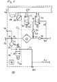
- FIG. 1 shows a section of a compressed air treatment plant shown schematically.
- the only partially represented compressed air treatment plant 10 has a compressed air inlet 12 to which usually a compressor is connected.
- the compressed air treatment plant 10 comprises a foreign filling port 76 via the compressed air also from an external compressed air source of the compressed air treatment system 10 can be supplied, for example, for service purposes in a workshop.
- a data bus connection 78 is provided, via which the compressed air treatment system 10 can communicate with other subsystems of the commercial vehicle, for example a motor control.
- the compressed air treatment plant 10 comprises a compressed air delivery line 16, which connects the compressed air inlet 12 with an air dryer cartridge 14.
- the air dryer cartridge 14 cleans the extracted compressed air from oil and dirt particles and removes moisture.
- the air dryer cartridge 14 usually comprises coalescing filters or other filtering means for removing the oil and dirt particles and a hygroscopic desiccant.
- the processed compressed air is passed downstream of the air dryer cartridge 14 via a check valve 46.
- a multi-circuit protection valve connection 70 is indicated, wherein the multi-circuit protection valve, which is no longer shown, can be a component that is separate from the compressed air treatment system 10 or integrated into the compressed air treatment system 10.
- conditioned compressed air bypassing the check valve 46, can regenerate the air dryer cartridge 14 by reversing the flow direction via a regeneration conduit 58, another check valve 48, and a throttle 50.
- a drain valve 18 is arranged, which may be designed for example as a 2/2-way valve.
- a screening element 24 is further arranged, which retains coarse dirt particles.
- the regeneration cycle may be controlled via a regeneration solenoid valve 56 disposed in the regeneration conduit 58 and may be configured, for example, as a 3/2-way valve.
- a closing spring 92 of the shut-off valve 18 can be biased via a control line 52, which rises from the regeneration line 58 at a branch point 54, to adjust the pneumatic opening pressure of the shut-off valve 18, for example between an opening pressure of about 9.5 to 10 bar when the Control line 52 is depressurized, and an opening pressure of about 16 to 17 bar when the control line 52 is pressurized.
- the shut-off valve 18 can be connected via a further control line 60 in the example of a 3/2-way valve designed solenoid valve 62nd is arranged to be controlled pneumatically.
- both the regeneration solenoid valve 56 and the solenoid valve 62 can be controlled simultaneously, so that the regeneration air via the strainer 24 and the shut-off valve 18 to the vent 80 to exit the system.
- the further control line 60 may have a further branch point 94, via which a further valve device 74 may be controlled, which in turn can put a compressor, not shown, which provides the compressed air at the compressed air inlet 12 in an energy-saving operating condition.
- the valve device 74 can enable a particularly rapid venting of the further control line 60 in order to change the operating state of the compressor more quickly.
- the shut-off valve 18 is simultaneously activated, so that a usually reduced compressed air flow rate of the compressor exits directly from the compressed air inlet via the screen element 24 and the shut-off valve 18 through the vent 80 from the system.
- a reduced amount of compressed air may be about 20 percent of the volume of compressed air normally delivered.
- the vent 80 may, as in FIG. 1 indicated to be coupled with other not shown components of the compressed air treatment system 10 via a further vent line 72. These components may also utilize the vent 80 to exhaust compressed air from the system.
- the vents indicated at the regeneration solenoid valve 56 and the solenoid valve 62 may also be coupled to the vent 80, wherein the explicit representation of corresponding connecting lines for better clarity has been omitted.
- the compressed air treatment system 10 includes a control unit 64, which can control the regeneration solenoid valve 56 and the solenoid valve 62 and can be coupled via the data bus connection 78 with other subsystems of the commercial vehicle. Also indicated are a heater 68 and a pressure sensor 66, which is controlled by the control unit 64, or via which the control unit 64 receives information about the pressure levels prevailing in the compressed air treatment system 10.
- the heater 68 can be used in particular to avoid the Zufrierens of pressure lines.
- the pressure sensor 66 is only To understand by way of example for a whole number of pressure sensors that can measure the pressure in the compressed air treatment system 10 at various points.
- pressure sensors may be arranged in front of and behind the screen element 24 in the vent line 22 in order to determine a back pressure dropping on the screen element 24 when the outlet valve 18 is open. In this way, a blockage of the screen element 24 can be detected, which would hinder the escape of compressed air during a regeneration cycle, which constipation may represent a change criterion.
- the drain valve 18 also serves as a safety valve to prevent a dangerous increase in pressure in the compressed air treatment system 10.
- a control line 96 is provided, via which the drain valve is opened when an adjustable safety pressure is exceeded.
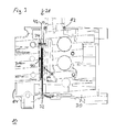
- FIG. 2 shows a three-dimensional sectional view of a housing of a compressed air treatment plant with a mounted screen element.
- the illustrated housing 30 has, in particular, an air dryer cartridge connection 82 on the upper side of the housing 30.
- an insertion channel 26 extends from above into the housing 30, wherein the insertion channel 26 is freely accessible from above, as long as the air dryer cartridge 14, not shown, is not mounted on the housing 30.
- the sieve element 24 is shown, wherein of the sieve element 24 is substantially a passage surface 32, that is, the surface of the actual sieve or the sieve surface, visible.
- a mounting member 42 is further shown, which is designed as a bracket which is pressed during assembly of the air dryer cartridge on the housing 30 down into the insertion channel 26, whereby the screen element 24 in the position shown within the Insertion channel 26 can be clamped.
- the illustrated insertion channel 26 extends in the axial direction 28 in the housing 30, wherein the axial direction 28 coincides with a mounting direction of the air dryer cartridge, not shown.
- the axial direction 28 in which the insertion channel 26 in the housing 30 does not extend with the mounting direction of the air dryer cartridge coincides.
- an access opening for the insertion channel 26 may be provided, which is not covered by the air dryer cartridge mounted, but has its own cover.
- the mounting element 42 is optional.
- the passage area 32 of the screen element 24 can extend up to the level of the air dryer cartridge connection 82, so that when the air dryer cartridge is mounted, the screen element 24 rests flush with the air dryer cartridge without the intermediary of a mounting element 42 and is fixed in the insertion channel 26 in this manner.
- the screen element 24 is fixedly coupled to the air dryer cartridge, not shown.
- the assembly process can be simplified, since during assembly of the air dryer cartridge automatically the screen element 24 is mounted.
- the coupling of the air dryer cartridge with the screen element 24 can be fixed, that is rigid, or flexible, that is movable, done.
- the mounting member 42 may be connected to a bottom plate, not shown, of the air dryer cartridge.
- the design of the coupling between the air dryer cartridge and the screen element is adapted to the possibility of connecting the air dryer cartridge to the housing 30.
- the air dryer cartridge connection via a bayonet coupling that is, the air dryer cartridge without rotation on the housing 30 can be placed and locked
- a rigid coupling between the sieve element 24 and the air dryer cartridge is particularly easy, and in the case of a rigid coupling, the screen element 24th For example, can be used as an anti-rotation against the housing during assembly of the air dryer cartridge.
- FIG. 3 shows a further three-dimensional sectional view of a housing of a compressed air treatment plant with a mounted screen element.
- the screen element 24 arranged inside the housing 30 can only be seen from the side, so that's out FIG. 2 already known passage surface 32 is substantially as a parallel to the axial direction 28 extending line.
- the passage surface 32 divides the insertion channel 26 in the axial direction 28 in a downstream side 38 and an inflow side 40.
- unprocessed compressed air from a compressor port 84 which can be identified with the compressed air inlet 12 or connected thereto, in the housing 30th promoted there rises in the insertion channel 26 on the upstream side 40 along up to the air dryer cartridge port 82 and from there further into the interior of the compressed air treatment plant 10.
- the flow direction is reversed and already processed compressed air, which is used to regenerate the air dryer cartridge, not shown is used, flows from the air dryer cartridge port 82 on the upstream side 40 down through the insertion channel at the passage surface 32 along.
- the air can not reach the downstream side 38 without passing through the passage surface 32, since a cross-sectional area 34 of the insertion channel 26 is suitably partially blocked.
- This embodiment of the screening element 24 is in the FIGS. 4 and 5 even more clearly visible.
- the laden with oil and dirt particles and moisture regeneration air passes through the passage surface 32 on the downstream side 38, wherein the coarse dirt particles are retained at the passage surface 32.
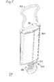
- FIG. 4 shows a three-dimensional view of a sieve element.
- the screen element 24 shown comprises a frame 86 in which the passage surface 32 is arranged.
- the passage area 32 comprises a screen grid, wherein the openings within the grid have a diameter of between about 0.5 and 1.5 millimeters, preferably about 1.0 millimeters, and the intermediate grid bars have a width of between about 0.5 millimeters and 0.9 Millimeters, preferably about 0.7 millimeters.
- Shown is the downstream side 38 of the screen element 24, on which a web 88 is arranged perpendicular to the passage surface 32 in the screen surface, which prevents a concern of the passage surface 32 against the wall of the insertion channel in the mounted state under varying pressure conditions.
- the web 88 further increases the stability of the passage surface 32 against bending during assembly.
- the cross-sectional area 34 of the insertion channel 26 can be seen, this being subdivided into a head surface 36 which, together with the passage surface 28, separates the downstream side 38 from the inflow side 40 in the insertion channel 26.
- the mounting member 42 in the form of a stirrup, which can be designed to be elastic and a Absetz phenomenon 44, which protects the inner wall of the insertion channel from dirt, visible.
- FIG. 5 shows a further three-dimensional view of a sieve element.
- a large part of the inflow side 40 is covered by a molded part 90, which may rest in the mounted state on a wall of the insertion channel and on its the passage surface 32 side facing out of FIG. 4 provides known settling surface 44.
- the molded part 90 thus forms a basket-like depression in which oil and dirt particles can collect.
- the lower edge of the frame 86 may be as in FIG FIG. 5 be shown widened on the inflow side 40, so that 40 falling oil and dirt particles can accumulate on the frame 86 on the inflow side. This can be assisted by pulling an edge of the frame 86 up to form a pocket.
Landscapes
- Engineering & Computer Science (AREA)
- Mechanical Engineering (AREA)
- Transportation (AREA)
- Chemical & Material Sciences (AREA)
- Analytical Chemistry (AREA)
- Physics & Mathematics (AREA)
- Fluid Mechanics (AREA)
- General Engineering & Computer Science (AREA)
- Valves And Accessory Devices For Braking Systems (AREA)
- Cooling, Air Intake And Gas Exhaust, And Fuel Tank Arrangements In Propulsion Units (AREA)
- Compressor (AREA)
- Drying Of Gases (AREA)
Priority Applications (1)
| Application Number | Priority Date | Filing Date | Title |
|---|---|---|---|
| EP17165141.7A EP3222479B1 (fr) | 2011-02-22 | 2012-02-20 | Élément filtrant d'une installation de préparation d'air comprimé pour un véhicule automobile |
Applications Claiming Priority (1)
| Application Number | Priority Date | Filing Date | Title |
|---|---|---|---|
| DE102011012031A DE102011012031B4 (de) | 2011-02-22 | 2011-02-22 | Druckluftaufbereitungsanlage und Verfahren zur Herstellung einer Druckluftaufbereitungsanlage |
Related Child Applications (2)
| Application Number | Title | Priority Date | Filing Date |
|---|---|---|---|
| EP17165141.7A Division-Into EP3222479B1 (fr) | 2011-02-22 | 2012-02-20 | Élément filtrant d'une installation de préparation d'air comprimé pour un véhicule automobile |
| EP17165141.7A Division EP3222479B1 (fr) | 2011-02-22 | 2012-02-20 | Élément filtrant d'une installation de préparation d'air comprimé pour un véhicule automobile |
Publications (3)
| Publication Number | Publication Date |
|---|---|
| EP2505444A2 true EP2505444A2 (fr) | 2012-10-03 |
| EP2505444A3 EP2505444A3 (fr) | 2017-08-02 |
| EP2505444B1 EP2505444B1 (fr) | 2018-11-14 |
Family
ID=45656167
Family Applications (2)
| Application Number | Title | Priority Date | Filing Date |
|---|---|---|---|
| EP17165141.7A Active EP3222479B1 (fr) | 2011-02-22 | 2012-02-20 | Élément filtrant d'une installation de préparation d'air comprimé pour un véhicule automobile |
| EP12156150.0A Active EP2505444B1 (fr) | 2011-02-22 | 2012-02-20 | Installation de traitement de l'air comprimé et procédé de fabrication d'une installation de traitement de l'air comprimé |
Family Applications Before (1)
| Application Number | Title | Priority Date | Filing Date |
|---|---|---|---|
| EP17165141.7A Active EP3222479B1 (fr) | 2011-02-22 | 2012-02-20 | Élément filtrant d'une installation de préparation d'air comprimé pour un véhicule automobile |
Country Status (3)
| Country | Link |
|---|---|
| EP (2) | EP3222479B1 (fr) |
| DE (1) | DE102011012031B4 (fr) |
| TR (2) | TR201902678T4 (fr) |
Cited By (2)
| Publication number | Priority date | Publication date | Assignee | Title |
|---|---|---|---|---|
| EP3666611A1 (fr) | 2018-12-12 | 2020-06-17 | WABCO Europe BVBA | Boîtier comportant un filtre de protection de soupape de purge |
| EP3789101A1 (fr) | 2019-09-06 | 2021-03-10 | KNORR-BREMSE Systeme für Nutzfahrzeuge GmbH | Dispositif de séchage à l'air et élément de tamis |
Families Citing this family (3)
| Publication number | Priority date | Publication date | Assignee | Title |
|---|---|---|---|---|
| DE102013006860A1 (de) | 2013-04-19 | 2014-10-23 | Knorr-Bremse Systeme für Nutzfahrzeuge GmbH | Pneumatisches System |
| DE102013007086A1 (de) * | 2013-04-24 | 2014-10-30 | Wabco Gmbh | Verfahren zum Steuern der Druckluftanlage eines mit Druckluft fremdbefüllten Kraftfahrzeugs |
| DE102013015157A1 (de) * | 2013-09-11 | 2015-03-12 | Wabco Gmbh | Luftaufbereitungsanlage für die Druckluftversorgung von Nutzkraftfahrzeugen |
Family Cites Families (8)
| Publication number | Priority date | Publication date | Assignee | Title |
|---|---|---|---|---|
| DE3324477A1 (de) * | 1983-03-05 | 1984-09-06 | Robert Bosch Gmbh, 7000 Stuttgart | Druckluftanlage von fahrzeugen, insbesondere druckluftbremsanlage |
| DE8602560U1 (de) * | 1986-01-31 | 1986-03-27 | Knorr-Bremse AG, 8000 München | Trocknungspatrone für Lufttrocknungsanlagen, insbesondere für Druckluftbremsanlagen von Fahrzeugen |
| US5600953A (en) * | 1994-09-28 | 1997-02-11 | Aisin Seiki Kabushiki Kaisha | Compressed air control apparatus |
| DE10351095B4 (de) * | 2003-10-31 | 2006-01-12 | Knorr-Bremse Systeme für Nutzfahrzeuge GmbH | Luftaufbereitungsanlage und Verfahren zum Versorgen einer Nutzkraftfahrzeugbremsanlage mit Druckluft |
| JP3884445B2 (ja) * | 2004-03-30 | 2007-02-21 | 日本無機株式会社 | エアフィルタろ材及びそれを用いたエアフィルタ |
| WO2009141876A1 (fr) * | 2008-05-20 | 2009-11-26 | イビデン株式会社 | Structure en nid d'abeille |
| DE102008026103A1 (de) * | 2008-05-30 | 2009-12-03 | Knorr-Bremse Systeme für Nutzfahrzeuge GmbH | Lufttrockner mit integrierter Regenerationssteuerung und Verfahren zum Betreiben eines Lufttrockners |
| DE102008053996B4 (de) * | 2008-10-30 | 2012-09-20 | Knorr-Bremse Systeme für Nutzfahrzeuge GmbH | Verfahren zum Betreiben einer Druckluftversorgungsanlage für ein Kraftfahrzeug |
-
2011
- 2011-02-22 DE DE102011012031A patent/DE102011012031B4/de active Active
-
2012
- 2012-02-20 TR TR2019/02678T patent/TR201902678T4/tr unknown
- 2012-02-20 TR TR2019/01417T patent/TR201901417T4/tr unknown
- 2012-02-20 EP EP17165141.7A patent/EP3222479B1/fr active Active
- 2012-02-20 EP EP12156150.0A patent/EP2505444B1/fr active Active
Non-Patent Citations (1)
| Title |
|---|
| None |
Cited By (3)
| Publication number | Priority date | Publication date | Assignee | Title |
|---|---|---|---|---|
| EP3666611A1 (fr) | 2018-12-12 | 2020-06-17 | WABCO Europe BVBA | Boîtier comportant un filtre de protection de soupape de purge |
| US11198084B2 (en) | 2018-12-12 | 2021-12-14 | Zf Cv Systems Europe Bv | Housing with filter for purge valve protection |
| EP3789101A1 (fr) | 2019-09-06 | 2021-03-10 | KNORR-BREMSE Systeme für Nutzfahrzeuge GmbH | Dispositif de séchage à l'air et élément de tamis |
Also Published As
| Publication number | Publication date |
|---|---|
| TR201902678T4 (tr) | 2019-03-21 |
| DE102011012031B4 (de) | 2012-12-06 |
| DE102011012031A1 (de) | 2012-08-23 |
| TR201901417T4 (tr) | 2019-02-21 |
| EP2505444A3 (fr) | 2017-08-02 |
| EP2505444B1 (fr) | 2018-11-14 |
| EP3222479A1 (fr) | 2017-09-27 |
| EP3222479B1 (fr) | 2018-12-12 |
Similar Documents
| Publication | Publication Date | Title |
|---|---|---|
| EP2768598B1 (fr) | Cartouche de filtre à air destinée au traitement d'air comprimé pour un système de traitement d'air comprimé | |
| EP2544933B1 (fr) | Cartouche de sécheur d'air et procédé permettant de faire fonctionner une cartouche de sécheur d'air | |
| EP2192971B1 (fr) | Cartouche de filtre a air pour un systeme d'alimentation en air comprime, avec boite de siccatif amovible | |
| EP2582560B2 (fr) | Dispositif, procédé et système de commande pneumatique et d'alimentation pneumatique | |
| DE102007039661B4 (de) | Kraftstofffilter | |
| EP2435160B1 (fr) | Procédé de traitement d'air comprimé, dispositif de traitement d'air comprimé et véhicule automobile équipé dudit dispositif | |
| EP2505444B1 (fr) | Installation de traitement de l'air comprimé et procédé de fabrication d'une installation de traitement de l'air comprimé | |
| DE102009030897A1 (de) | Lufttrocknerpatrone für eine Druckluftaufbereitungsanlage eines Fahrzeugs und Verfahren zur Herstellung einer Lufttrocknerpatrone | |
| DE112010002173T5 (de) | Filteranordnung mit Wartung bei zurückgehaltenem SchadstoffSchadstoff | |
| DE102007011246B4 (de) | Druckluftversorgungseinrichtung und Ventilgehäuse | |
| DE102013103066A1 (de) | Luftfilterpatrone mit integriertem Koaleszenzfilter/Grobschmutzfilter und Trockenmittelfüllung | |
| WO2011160735A1 (fr) | Dispositif d'alimentation en air pour un véhicule à moteur, pourvu d'appareils pneumatiques | |
| EP3359282B1 (fr) | Cartouche de séchage pour séchage et régénération améliorés | |
| EP1640232B1 (fr) | Dispositif de distribution d'air comprimé d'un système à air comprimé d'un véhicule commerciale | |
| EP3332861A1 (fr) | Système d'air sec pour dessiccateur des granululés | |
| DE102018000981A1 (de) | Strömungsoptimierte Trockenmittelkartusche | |
| EP2385913B1 (fr) | Dispositif d'alimentation en air comprimé | |
| DE102005019672A1 (de) | Filtersystem | |
| EP2141055A2 (fr) | Soupape de sécurité pour une commande d'engrenage pneumatique | |
| DE102024113975A1 (de) | Druckluftversorgungsanlage für ein pneumatisches System eines Fahrzeugs, pneumatisches System mit Druckluftversorgungsanlage und Pneumatikanlage, Fahrzeug mit einem pneumatischen System und Verfahren zum Betreiben einer Druckluftversorgungsanlage oder eines pneumatischen Systems oder von beidem |
Legal Events
| Date | Code | Title | Description |
|---|---|---|---|
| PUAI | Public reference made under article 153(3) epc to a published international application that has entered the european phase |
Free format text: ORIGINAL CODE: 0009012 |
|
| AK | Designated contracting states |
Kind code of ref document: A2 Designated state(s): AL AT BE BG CH CY CZ DE DK EE ES FI FR GB GR HR HU IE IS IT LI LT LU LV MC MK MT NL NO PL PT RO RS SE SI SK SM TR |
|
| AX | Request for extension of the european patent |
Extension state: BA ME |
|
| PUAL | Search report despatched |
Free format text: ORIGINAL CODE: 0009013 |
|
| AK | Designated contracting states |
Kind code of ref document: A3 Designated state(s): AL AT BE BG CH CY CZ DE DK EE ES FI FR GB GR HR HU IE IS IT LI LT LU LV MC MK MT NL NO PL PT RO RS SE SI SK SM TR |
|
| AX | Request for extension of the european patent |
Extension state: BA ME |
|
| RIC1 | Information provided on ipc code assigned before grant |
Ipc: B60T 17/00 20060101AFI20170628BHEP |
|
| STAA | Information on the status of an ep patent application or granted ep patent |
Free format text: STATUS: REQUEST FOR EXAMINATION WAS MADE |
|
| 17P | Request for examination filed |
Effective date: 20180202 |
|
| RBV | Designated contracting states (corrected) |
Designated state(s): AL AT BE BG CH CY CZ DE DK EE ES FI FR GB GR HR HU IE IS IT LI LT LU LV MC MK MT NL NO PL PT RO RS SE SI SK SM TR |
|
| GRAP | Despatch of communication of intention to grant a patent |
Free format text: ORIGINAL CODE: EPIDOSNIGR1 |
|
| STAA | Information on the status of an ep patent application or granted ep patent |
Free format text: STATUS: GRANT OF PATENT IS INTENDED |
|
| INTG | Intention to grant announced |
Effective date: 20180615 |
|
| RIN1 | Information on inventor provided before grant (corrected) |
Inventor name: REIFINGER, GUENTHER Inventor name: CABARISTE, HUBERT Inventor name: SCHNITTGER, KARSTEN Inventor name: HUBER, GEORG |
|
| GRAS | Grant fee paid |
Free format text: ORIGINAL CODE: EPIDOSNIGR3 |
|
| GRAA | (expected) grant |
Free format text: ORIGINAL CODE: 0009210 |
|
| STAA | Information on the status of an ep patent application or granted ep patent |
Free format text: STATUS: THE PATENT HAS BEEN GRANTED |
|
| AK | Designated contracting states |
Kind code of ref document: B1 Designated state(s): AL AT BE BG CH CY CZ DE DK EE ES FI FR GB GR HR HU IE IS IT LI LT LU LV MC MK MT NL NO PL PT RO RS SE SI SK SM TR |
|
| REG | Reference to a national code |
Ref country code: CH Ref legal event code: EP Ref country code: AT Ref legal event code: REF Ref document number: 1064436 Country of ref document: AT Kind code of ref document: T Effective date: 20181115 |
|
| REG | Reference to a national code |
Ref country code: DE Ref legal event code: R096 Ref document number: 502012013803 Country of ref document: DE |
|
| REG | Reference to a national code |
Ref country code: IE Ref legal event code: FG4D Free format text: LANGUAGE OF EP DOCUMENT: GERMAN |
|
| REG | Reference to a national code |
Ref country code: SE Ref legal event code: TRGR |
|
| REG | Reference to a national code |
Ref country code: LT Ref legal event code: MG4D |
|
| REG | Reference to a national code |
Ref country code: NL Ref legal event code: FP |
|
| PG25 | Lapsed in a contracting state [announced via postgrant information from national office to epo] |
Ref country code: LT Free format text: LAPSE BECAUSE OF FAILURE TO SUBMIT A TRANSLATION OF THE DESCRIPTION OR TO PAY THE FEE WITHIN THE PRESCRIBED TIME-LIMIT Effective date: 20181114 Ref country code: NO Free format text: LAPSE BECAUSE OF FAILURE TO SUBMIT A TRANSLATION OF THE DESCRIPTION OR TO PAY THE FEE WITHIN THE PRESCRIBED TIME-LIMIT Effective date: 20190214 Ref country code: HR Free format text: LAPSE BECAUSE OF FAILURE TO SUBMIT A TRANSLATION OF THE DESCRIPTION OR TO PAY THE FEE WITHIN THE PRESCRIBED TIME-LIMIT Effective date: 20181114 Ref country code: LV Free format text: LAPSE BECAUSE OF FAILURE TO SUBMIT A TRANSLATION OF THE DESCRIPTION OR TO PAY THE FEE WITHIN THE PRESCRIBED TIME-LIMIT Effective date: 20181114 Ref country code: IS Free format text: LAPSE BECAUSE OF FAILURE TO SUBMIT A TRANSLATION OF THE DESCRIPTION OR TO PAY THE FEE WITHIN THE PRESCRIBED TIME-LIMIT Effective date: 20190314 Ref country code: BG Free format text: LAPSE BECAUSE OF FAILURE TO SUBMIT A TRANSLATION OF THE DESCRIPTION OR TO PAY THE FEE WITHIN THE PRESCRIBED TIME-LIMIT Effective date: 20190214 Ref country code: ES Free format text: LAPSE BECAUSE OF FAILURE TO SUBMIT A TRANSLATION OF THE DESCRIPTION OR TO PAY THE FEE WITHIN THE PRESCRIBED TIME-LIMIT Effective date: 20181114 Ref country code: FI Free format text: LAPSE BECAUSE OF FAILURE TO SUBMIT A TRANSLATION OF THE DESCRIPTION OR TO PAY THE FEE WITHIN THE PRESCRIBED TIME-LIMIT Effective date: 20181114 |
|
| PG25 | Lapsed in a contracting state [announced via postgrant information from national office to epo] |
Ref country code: GR Free format text: LAPSE BECAUSE OF FAILURE TO SUBMIT A TRANSLATION OF THE DESCRIPTION OR TO PAY THE FEE WITHIN THE PRESCRIBED TIME-LIMIT Effective date: 20190215 Ref country code: RS Free format text: LAPSE BECAUSE OF FAILURE TO SUBMIT A TRANSLATION OF THE DESCRIPTION OR TO PAY THE FEE WITHIN THE PRESCRIBED TIME-LIMIT Effective date: 20181114 Ref country code: AL Free format text: LAPSE BECAUSE OF FAILURE TO SUBMIT A TRANSLATION OF THE DESCRIPTION OR TO PAY THE FEE WITHIN THE PRESCRIBED TIME-LIMIT Effective date: 20181114 Ref country code: PT Free format text: LAPSE BECAUSE OF FAILURE TO SUBMIT A TRANSLATION OF THE DESCRIPTION OR TO PAY THE FEE WITHIN THE PRESCRIBED TIME-LIMIT Effective date: 20190314 |
|
| PG25 | Lapsed in a contracting state [announced via postgrant information from national office to epo] |
Ref country code: PL Free format text: LAPSE BECAUSE OF FAILURE TO SUBMIT A TRANSLATION OF THE DESCRIPTION OR TO PAY THE FEE WITHIN THE PRESCRIBED TIME-LIMIT Effective date: 20181114 Ref country code: DK Free format text: LAPSE BECAUSE OF FAILURE TO SUBMIT A TRANSLATION OF THE DESCRIPTION OR TO PAY THE FEE WITHIN THE PRESCRIBED TIME-LIMIT Effective date: 20181114 Ref country code: CZ Free format text: LAPSE BECAUSE OF FAILURE TO SUBMIT A TRANSLATION OF THE DESCRIPTION OR TO PAY THE FEE WITHIN THE PRESCRIBED TIME-LIMIT Effective date: 20181114 |
|
| REG | Reference to a national code |
Ref country code: DE Ref legal event code: R097 Ref document number: 502012013803 Country of ref document: DE |
|
| PG25 | Lapsed in a contracting state [announced via postgrant information from national office to epo] |
Ref country code: RO Free format text: LAPSE BECAUSE OF FAILURE TO SUBMIT A TRANSLATION OF THE DESCRIPTION OR TO PAY THE FEE WITHIN THE PRESCRIBED TIME-LIMIT Effective date: 20181114 Ref country code: EE Free format text: LAPSE BECAUSE OF FAILURE TO SUBMIT A TRANSLATION OF THE DESCRIPTION OR TO PAY THE FEE WITHIN THE PRESCRIBED TIME-LIMIT Effective date: 20181114 Ref country code: SM Free format text: LAPSE BECAUSE OF FAILURE TO SUBMIT A TRANSLATION OF THE DESCRIPTION OR TO PAY THE FEE WITHIN THE PRESCRIBED TIME-LIMIT Effective date: 20181114 Ref country code: SK Free format text: LAPSE BECAUSE OF FAILURE TO SUBMIT A TRANSLATION OF THE DESCRIPTION OR TO PAY THE FEE WITHIN THE PRESCRIBED TIME-LIMIT Effective date: 20181114 |
|
| PLBE | No opposition filed within time limit |
Free format text: ORIGINAL CODE: 0009261 |
|
| STAA | Information on the status of an ep patent application or granted ep patent |
Free format text: STATUS: NO OPPOSITION FILED WITHIN TIME LIMIT |
|
| REG | Reference to a national code |
Ref country code: CH Ref legal event code: PL |
|
| 26N | No opposition filed |
Effective date: 20190815 |
|
| PG25 | Lapsed in a contracting state [announced via postgrant information from national office to epo] |
Ref country code: LU Free format text: LAPSE BECAUSE OF NON-PAYMENT OF DUE FEES Effective date: 20190220 Ref country code: SI Free format text: LAPSE BECAUSE OF FAILURE TO SUBMIT A TRANSLATION OF THE DESCRIPTION OR TO PAY THE FEE WITHIN THE PRESCRIBED TIME-LIMIT Effective date: 20181114 Ref country code: MC Free format text: LAPSE BECAUSE OF FAILURE TO SUBMIT A TRANSLATION OF THE DESCRIPTION OR TO PAY THE FEE WITHIN THE PRESCRIBED TIME-LIMIT Effective date: 20181114 |
|
| REG | Reference to a national code |
Ref country code: BE Ref legal event code: MM Effective date: 20190228 |
|
| REG | Reference to a national code |
Ref country code: IE Ref legal event code: MM4A |
|
| PG25 | Lapsed in a contracting state [announced via postgrant information from national office to epo] |
Ref country code: CH Free format text: LAPSE BECAUSE OF NON-PAYMENT OF DUE FEES Effective date: 20190228 Ref country code: LI Free format text: LAPSE BECAUSE OF NON-PAYMENT OF DUE FEES Effective date: 20190228 |
|
| PG25 | Lapsed in a contracting state [announced via postgrant information from national office to epo] |
Ref country code: IE Free format text: LAPSE BECAUSE OF NON-PAYMENT OF DUE FEES Effective date: 20190220 |
|
| PG25 | Lapsed in a contracting state [announced via postgrant information from national office to epo] |
Ref country code: BE Free format text: LAPSE BECAUSE OF NON-PAYMENT OF DUE FEES Effective date: 20190228 |
|
| REG | Reference to a national code |
Ref country code: AT Ref legal event code: MM01 Ref document number: 1064436 Country of ref document: AT Kind code of ref document: T Effective date: 20190220 |
|
| PG25 | Lapsed in a contracting state [announced via postgrant information from national office to epo] |
Ref country code: AT Free format text: LAPSE BECAUSE OF NON-PAYMENT OF DUE FEES Effective date: 20190220 |
|
| PG25 | Lapsed in a contracting state [announced via postgrant information from national office to epo] |
Ref country code: MT Free format text: LAPSE BECAUSE OF FAILURE TO SUBMIT A TRANSLATION OF THE DESCRIPTION OR TO PAY THE FEE WITHIN THE PRESCRIBED TIME-LIMIT Effective date: 20181114 |
|
| PG25 | Lapsed in a contracting state [announced via postgrant information from national office to epo] |
Ref country code: CY Free format text: LAPSE BECAUSE OF FAILURE TO SUBMIT A TRANSLATION OF THE DESCRIPTION OR TO PAY THE FEE WITHIN THE PRESCRIBED TIME-LIMIT Effective date: 20181114 |
|
| PG25 | Lapsed in a contracting state [announced via postgrant information from national office to epo] |
Ref country code: HU Free format text: LAPSE BECAUSE OF FAILURE TO SUBMIT A TRANSLATION OF THE DESCRIPTION OR TO PAY THE FEE WITHIN THE PRESCRIBED TIME-LIMIT; INVALID AB INITIO Effective date: 20120220 |
|
| PG25 | Lapsed in a contracting state [announced via postgrant information from national office to epo] |
Ref country code: MK Free format text: LAPSE BECAUSE OF FAILURE TO SUBMIT A TRANSLATION OF THE DESCRIPTION OR TO PAY THE FEE WITHIN THE PRESCRIBED TIME-LIMIT Effective date: 20181114 |
|
| PGFP | Annual fee paid to national office [announced via postgrant information from national office to epo] |
Ref country code: NL Payment date: 20230220 Year of fee payment: 12 |
|
| PGFP | Annual fee paid to national office [announced via postgrant information from national office to epo] |
Ref country code: IT Payment date: 20230228 Year of fee payment: 12 |
|
| P01 | Opt-out of the competence of the unified patent court (upc) registered |
Effective date: 20230607 |
|
| REG | Reference to a national code |
Ref country code: NL Ref legal event code: MM Effective date: 20240301 |
|
| PG25 | Lapsed in a contracting state [announced via postgrant information from national office to epo] |
Ref country code: NL Free format text: LAPSE BECAUSE OF NON-PAYMENT OF DUE FEES Effective date: 20240301 |
|
| PG25 | Lapsed in a contracting state [announced via postgrant information from national office to epo] |
Ref country code: NL Free format text: LAPSE BECAUSE OF NON-PAYMENT OF DUE FEES Effective date: 20240301 |
|
| PG25 | Lapsed in a contracting state [announced via postgrant information from national office to epo] |
Ref country code: IT Free format text: LAPSE BECAUSE OF NON-PAYMENT OF DUE FEES Effective date: 20240220 |
|
| PGFP | Annual fee paid to national office [announced via postgrant information from national office to epo] |
Ref country code: SE Payment date: 20260223 Year of fee payment: 15 |
|
| PGFP | Annual fee paid to national office [announced via postgrant information from national office to epo] |
Ref country code: GB Payment date: 20260223 Year of fee payment: 15 |
|
| PGFP | Annual fee paid to national office [announced via postgrant information from national office to epo] |
Ref country code: DE Payment date: 20260220 Year of fee payment: 15 |
|
| PGFP | Annual fee paid to national office [announced via postgrant information from national office to epo] |
Ref country code: FR Payment date: 20260224 Year of fee payment: 15 |
|
| PGFP | Annual fee paid to national office [announced via postgrant information from national office to epo] |
Ref country code: TR Payment date: 20260203 Year of fee payment: 15 |