EP2505449A1 - Support fileté avec bloc d'ancrage - Google Patents
Support fileté avec bloc d'ancrage Download PDFInfo
- Publication number
- EP2505449A1 EP2505449A1 EP20120161496 EP12161496A EP2505449A1 EP 2505449 A1 EP2505449 A1 EP 2505449A1 EP 20120161496 EP20120161496 EP 20120161496 EP 12161496 A EP12161496 A EP 12161496A EP 2505449 A1 EP2505449 A1 EP 2505449A1
- Authority
- EP
- European Patent Office
- Prior art keywords
- nut
- holding block
- enclosure
- opening
- block
- Prior art date
- Legal status (The legal status is an assumption and is not a legal conclusion. Google has not performed a legal analysis and makes no representation as to the accuracy of the status listed.)
- Granted
Links
Images

Classifications
-
- B—PERFORMING OPERATIONS; TRANSPORTING
- B61—RAILWAYS
- B61D—BODY DETAILS OR KINDS OF RAILWAY VEHICLES
- B61D17/00—Construction details of vehicle bodies
- B61D17/04—Construction details of vehicle bodies with bodies of metal; with composite, e.g. metal and wood body structures
- B61D17/12—Roofs
-
- F—MECHANICAL ENGINEERING; LIGHTING; HEATING; WEAPONS; BLASTING
- F16—ENGINEERING ELEMENTS AND UNITS; GENERAL MEASURES FOR PRODUCING AND MAINTAINING EFFECTIVE FUNCTIONING OF MACHINES OR INSTALLATIONS; THERMAL INSULATION IN GENERAL
- F16B—DEVICES FOR FASTENING OR SECURING CONSTRUCTIONAL ELEMENTS OR MACHINE PARTS TOGETHER, e.g. NAILS, BOLTS, CIRCLIPS, CLAMPS, CLIPS OR WEDGES; JOINTS OR JOINTING
- F16B37/00—Nuts or like thread-engaging members
- F16B37/04—Devices for fastening nuts to surfaces, e.g. sheets, plates
- F16B37/044—Nut cages
Definitions
- the present invention relates to a thread carrier, in particular for use in rail vehicles, and a method for fastening components on the roof of a rail vehicle.
- a cage nut is a mostly square steel nut with a central thread in a cage made of sheet metal, so that any turning of the nut when tightening the screw is excluded.
- Cage nuts are primarily used when mounting devices in 19-inch racks, such as components of servers, network distributors or lab equipment. But cage nuts are not available for any size and strength classes and removal of the mother from the cage for the purpose of replacement without destroying the cage is usually no longer possible.
- DE1930609 describes a cage nut with a steel frame, in which a mother of sheet steel or resilient material finds its reception.
- a weld nut is attached by means of a welded connection to a base, which can not rotate when tightening a screw, so that the nut is held by the weld not twisted.
- the disadvantage is that the welded joint is permanent and a once welded nut is no longer interchangeable.
- sliding blocks are known from the prior art, by means of which one can determine attachments to a rail.
- DE 29713008 U1 describes a sliding block having a top, a bottom and an edge therebetween, a bore extending from the top to the bottom and a non-round recess concentric therewith in the top for rotationally receiving a screw.
- DE 20217838 U1 describes a sliding block for fixing elements to a rail consisting of a molded part, which can be moved in the dissolved state in a C-shaped profiled rail, wherein pressed in the clamped state, the molded part against the mutually aligned leg ends of the C-profile.
- the molding has a substantially cuboid shape, with a recess and an opening for receiving a screw head or a nut.
- the cuboid is profiled so that it can be inserted in a first position from its longitudinal sides and forth between the leg ends, and that it can be fixed by pivoting in a second position in the groove region of the profile rail.
- sliding blocks When using sliding blocks, other disadvantages occur: For safety reasons, removable fasteners such as screws, nuts and washers are exchanged when a screw connection is loosened again. If conventional sliding blocks are used in a screw connection, which were loaded on train, they must also be replaced. Due to the loads to be absorbed, sliding blocks are often special parts made of very solid materials, such as special steel, so that replacement is associated with high costs.
- the object of the present invention was to provide a thread carrier which solves one or more of the above problems.
- the thread carrier should be easy to handle, have high strength and rigidity and be suitable for mounting components on the roof of a rail vehicle.
- the threaded carrier is an arrangement in which a screw can be screwed in and does not turn in the direction of rotation of the screw when screwing a screw.
- a part for example, a component of a rail vehicle to be attached to the threaded carrier.
- An advantage of the invention is that the holding block can be used in inaccessible places where a lock nut can be heavily countered, and that it is held there by the enclosure.
- the thread carrier causes that when screwing a screw into the nut, which is by definition a part of the thread carrier, a co-rotation of the nut is prevented when tightening the screw.
- the nut is held by the holding block and the holding block is in turn held in the enclosure.
- a torque exerted on the nut is transmitted to the holding block.
- the holding block in turn strikes against the enclosure, so that one revolution of the holding block and the nut therein is prevented.
- the holding block can have more or less movement in the enclosure.
- the game is but at most so large that the holding block abuts the casing during a rotational movement about the longitudinal axis of a screwed into the nut on the enclosure, so that one revolution of the holding block and the nut is prevented.
- Specific embodiments of a holding block will be given elsewhere in this description.
- An advantage of the thread carrier of the present invention is that after loosening the screw for safety reasons, only a nut and a screw must be replaced, but not the holding block. This results in a material and cost savings.
- nuts of any strength classes can be used, which is not the case with sliding blocks.
- high torques can be applied to a holding stone and thread carrier according to the invention without it being damaged, for example by irreversible deformation. This is especially true when the holding block is made of solid metal or stone.
- the nut inserted into the retainer block is adjacent to the enclosure and adjacent to the opening in the enclosure through which the nut is accessible for driving a screw so that upon tightening the screw the nut is pressed against the enclosure, and is not pressed in the longitudinal direction of the screw against the holding block.
- the function mechanism can be described as follows: When using the thread carrier, a screw is passed through the opening in the enclosure and screwed into the located on the other side of the opening nut, which is inserted into the holding block. When turning the screw, the holding block rotates first with and strikes against the enclosure, as stated above. When tightening the screw, the nut is pulled against the enclosure and comes to the enclosure, or at the edge of the hole in the enclosure to lie.
- the mother can be pulled out of the holding block something when the enclosure, the holding block and nut are dimensioned so that between the mother and the enclosure (in the non-tightened state of the screw) is formed a gap and the holding block and the mother with appropriate Game are used in the enclosure.
- the nut is in this case, although form-fitting and non-rotatably inserted against the holding block in the opening of the holding block, but it can be pulled out of the holding block when tightening the screw something without leaving the holding block completely.
- backing materials in particular slip-resistant materials, may be arranged, for example rubber elements, which are preferably firmly connected either to the nut or to the enclosure.
- T-nuts from the prior art are used in other ways. They are loaded with tension when inserted into a groove or C-rail.
- the retaining block is merely to prevent rotation of the nut, since it abuts the enclosure in which it is inserted.
- torque is applied at the beginning of tightening the screw, which is reduced in the course of tightening when the nut is applied to the enclosure and predominantly already by the friction between the nut and the enclosure prevents rotation of the nut.
- the support block substantially prevents rotation of the nut at the beginning of tightening the screw.
- the support block is loaded in this embodiment in the longitudinal direction of the screw neither train, as is the case with sliding blocks of the prior art, nor charged to pressure.
- the holding block may therefore be made of a less solid material than a sliding block.
- the thread carrier of the holding block with a nut inserted therein from the enclosure is removed again.
- the retaining stone and the nut inserted therein can be easily replaced.
- the term "removable" in this context means that the holding block can be removed with a nut inserted therein from the enclosure, without that the enclosure must be changed in shape, for example by bending. The removability is thus possible without the enclosure must be changed or destroyed.
- the retaining stone is inserted into the enclosure or inserted into the enclosure.
- the enclosure encloses the retaining block with the exception of one side or with the exception of two opposite sides, so that the retaining block is inserted into the enclosure and also from the enclosure by moving removable. Further, the enclosure encloses the retaining block with the exception of the opening, or the openings through which the nut is accessible for the purpose of screwing the screw.
- One or more insertion openings in the enclosure for insertion of the holding block and an opening for insertion of the screw are preferably on different sides of the enclosure arranged.
- the longitudinal axis of a screw screwed into the threaded carrier is in particular transversely, most preferably perpendicular, to the insertion direction of the holding block in the enclosure.
- the retainer block has a polygonal cross-section, in particular a rectangular cross section, when the cuboid is in the shape of a cuboid or cube, and the enclosure has two complementary or substantially complementary shaped apertures.
- the enclosure has a polygonal, in particular rectangular, cross-section into which a complementarily shaped holding block with a nut inserted into it can be inserted.
- the enclosure may be in the form of a tube or chamber of polygonal, in particular rectangular cross-section, the tube / chamber having two openings, preferably opposite openings, for insertion (or removal) of a holding block.
- the retaining block is pushed into the enclosure until the threaded hole of the nut and that opening in the enclosure through which the nut is accessible for the purpose of screwing in a screw, are brought to coincide.
- the holding block and the enclosure are the same length or substantially the same length, wherein the length is meant in the insertion direction.
- the retaining block is inserted into the enclosure until the edges of the enclosure and the edges of the holding block are flush with each other or substantially flush with each other, which can be done manually in a simple manner.
- the opening in the enclosure is arranged so that when flush position of the holding block in the enclosure, the opening of the nut in the holding block and the opening in the enclosure are brought to coincide. Since the flush layer can be easily controlled manually, a positioning of the holding block is particularly simple, especially in poorly accessible or poorly visible places.
- the opening in the support block wherein the nut is insertable is a through opening
- the enclosure has openings on both sides of the support block and the nut, the openings being axially aligned along the longitudinal axis of a screw penetrates the casing, the nut and the retaining block.
- the retaining block has a continuous opening for insertion of a nut screws can be used, which penetrate the holding block due to their length after screwing into the nut.
- the enclosure also has a further opening so that the screw can also penetrate the enclosure.
- the enclosure in this embodiment has an opening on both sides of the holding block and the nut, wherein the openings are axially aligned along a screw longitudinal axis, so that the screw can penetrate the mother used in the retaining stone, the retaining stone and the enclosure.
- the nut is removable from the holding block again.
- This embodiment is particularly advantageous, although the holding block can be removed from its enclosure.
- the nut preferably has on one side a laterally projecting collar which rests after insertion of the nut in the holding stone on the surface of the holding stone, so that the nut does not slip through the opening of the holding block.
- the enclosure can have elements with which it can be attached to a substrate, for example by screwing, gluing, riveting, plugging or welding.
- the enclosure may for example have tabs with holes that can be bolted to a substrate.
- the enclosure can also have arms that can be welded to a substrate. Any variants are conceivable.
- the invention in a further aspect, relates to a retaining block for a nut, having an opening with a non-rotationally symmetrical contour into which a nut with a complementary outer contour can be inserted in a form-fitting manner and against the retaining block in a non-rotatable manner.
- the holding block can be used as a component of a previously described thread carrier and all embodiments of a holding block described below can be used accordingly in a threaded carrier.
- the opening for receiving the nut has a polygonal contour, in particular a hexagonal contour for receiving hexagonal nuts.
- the opening may be continuous or non-continuous, with a through opening having the advantage that screws can be used which penetrate the holding block due to their length after screwing into the nut.
- the holding block made of metal or stone. Furthermore, the holding block preferably has the shape of a cuboid or cube. The corners and edges of the holding block are preferably rounded.
- the nut is preferably removed from the holding block again.
- the dimensioning of the opening in the holding block is selected accordingly.
- the opening in the holding block may be continuous or not continuous.
- the nut preferably has on one side a laterally projecting collar which rests after insertion of the nut in the holding stone on the surface of the holding stone, so that the nut does not slip through the opening of the holding block.
- This arrangement is also usable in the thread carrier described above.
- the invention also relates to a railcar having one or more threaded carriers as previously described.
- the thread carriers are arranged in the region of the roof of a rail vehicle car.
- the invention thus also relates to a rail vehicle car, on the roof of which one or more threaded carriers are arranged as described above, wherein the threaded carriers are provided for fixing roof components.
- the threaded carriers can thus preferably serve for fastening components on the roof, in particular in a flat roof area.
- Preferred components are replaceable components. In particular, these are also components with a mass, for their secure fastening screws and nuts of a high strength class are required. Examples of components are air conditioning systems, pantographs, energy storage or drive devices.
- the attachment of the threaded carrier in the region of the roof can be done for example by welding, riveting, plugging, screwing or gluing, wherein preferably the enclosure of the threaded carrier in the region of the roof, preferably on the roof, is attached.
- the enclosure is attached to a supporting area of the roof, in particular to a roof rack.
- the method described above may refer to one or a plurality of enclosures, nuts, retaining blocks, screws and threaded fasteners. Furthermore, the method relates to all holding blocks, arrangements and thread carriers described in this description and the exemplary embodiments.
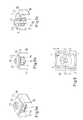
- Fig. 1 shows a block-shaped holding block 1, made of stone, with rounded edges 2 and 3 corners.
- the holding block has a non-rotationally symmetrical, hexagonal opening 4, which is continuous.
- the Fig. 2 shows an inserted into the opening 4 hexagonal nut 5.
- the nut 5 is positively and against the holding block 1 is not rotatably inserted into the opening 4 of the holding block.
- a screw can be screwed.
- the nut 5 has on one side a laterally projecting collar 7, which in contrast to the hexagonal nut base has a circular contour.
- the collar 7 is after insertion of the nut 5 in the retaining stone 1 on the surface 8 of the retaining stone 1, so that it does not slip through the opening 4 of the holding block 1.
- the connector between the holding block 1 and nut 5 is releasable again, so that the nut can be removed by pulling up from the holding block.
- Fig. 3 shows an enclosure 9, in which an arrangement according to Fig. 4 can be used.
- the enclosure is composed of two different sized U-profile pieces 10, 11.
- the smaller U-profile 11 is clamped with tabs (not visible) in recesses 12 of the larger U-profile 10.
- the two U-profiles 10, 11 form a space 13 with a rectangular cross-section, which has openings on two opposite sides.
- the enclosure has two axially aligned openings 14, 15.
- the enclosure 9 can be secured with the lateral legs 16, 17 of the large U-profile 10 on a substrate, for example by plugging or welding.
- the Fig. 4 shows an assembled threaded carrier 20, composed of an enclosure 9 according to Fig. 3 and an arrangement of retaining stone 1 and nut 5 according to Fig. 2 ,
- the arrangement of retaining stone 1 and nut 5 was pushed laterally through one of its openings in the space 13 until the threaded hole 6 of the nut 5 is brought to the opening 14 of the enclosure 9 to coincide.
- the nut 5 inserted in the retainer block 1 is located adjacent to the opening 14 in the enclosure 9, as well as in the lateral view of FIG Fig. 5b and 5c to see.
- Fig. 5a-5c is a part to be screwed 21 placed on the threaded carrier and screwed with a screw 22 to the threaded carrier. Between the screw 22 and the part 21, a washer 23 is arranged. The screw 22 penetrates both the holding block 1 and the enclosure, leaving the enclosure through the opening 15 again.
- Fig. 5a and 5b is particularly good to see how the holding block 1 and the nut 5 are pushed into the rectangular tube of the enclosure, which are formed from the U-profiles 10 and 11. As well as retaining block and nut were inserted, they can be removed manually after removal of the screw 22, by moving it to the side in the direction of one of the openings of the space 13.
- Fig. 5b It can be seen that the holding block 1 is mounted with a little clearance to the side in the space 13 of the enclosure.
- FIG. 6 is shown in a plan view of the threaded carrier, as the holding block 1 moves when tightening the screw within the space 13 of the enclosure 9. From the enclosure only the smaller U-profile 11 is shown.
- the holding block 1 is mounted with some play in the tube formed from small and large U-profile 10, 11.
- the retaining stone rotates in the direction of arrow until it strikes with two diagonally opposite corners 3 and 2 edges on the U-profile 11, causing a further rotation is prevented.
- the nut 5 is pressed against the enclosure 9 and the frictional force between the nut 5 and enclosure 9 takes on the applied torque of the screw 22. If there is a gap between the collar 7 of the nut 5 and the enclosure 9, the nut is slightly pulled out of the holding block 1 when tightening the screw 22 until it rests with the collar 7 on the enclosure.
Landscapes
- Engineering & Computer Science (AREA)
- General Engineering & Computer Science (AREA)
- Mechanical Engineering (AREA)
- Life Sciences & Earth Sciences (AREA)
- Wood Science & Technology (AREA)
- Fittings On The Vehicle Exterior For Carrying Loads, And Devices For Holding Or Mounting Articles (AREA)
Priority Applications (1)
| Application Number | Priority Date | Filing Date | Title |
|---|---|---|---|
| PL12161496T PL2505449T3 (pl) | 2011-03-30 | 2012-03-27 | Gniazdo gwintowane wyposażone w element ustalający |
Applications Claiming Priority (1)
| Application Number | Priority Date | Filing Date | Title |
|---|---|---|---|
| DE201110006465 DE102011006465A1 (de) | 2011-03-30 | 2011-03-30 | Haltestein für Schraubenmutter und Gewindeträger aufweisend den Haltestein |
Publications (2)
| Publication Number | Publication Date |
|---|---|
| EP2505449A1 true EP2505449A1 (fr) | 2012-10-03 |
| EP2505449B1 EP2505449B1 (fr) | 2016-06-15 |
Family
ID=45954402
Family Applications (1)
| Application Number | Title | Priority Date | Filing Date |
|---|---|---|---|
| EP12161496.0A Active EP2505449B1 (fr) | 2011-03-30 | 2012-03-27 | Support fileté avec bloc d'ancrage |
Country Status (4)
| Country | Link |
|---|---|
| EP (1) | EP2505449B1 (fr) |
| DE (1) | DE102011006465A1 (fr) |
| ES (1) | ES2586755T3 (fr) |
| PL (1) | PL2505449T3 (fr) |
Cited By (6)
| Publication number | Priority date | Publication date | Assignee | Title |
|---|---|---|---|---|
| WO2014082832A1 (fr) * | 2012-11-30 | 2014-06-05 | Siemens Aktiengesellschaft | Console permettant de relier à un véhicule ferroviaire des superstructures de toit |
| WO2014111224A1 (fr) * | 2013-01-17 | 2014-07-24 | Siemens Aktiengesellschaft | Fixation d'un élément de véhicule ferroviaire sur un toit d'une caisse de véhicule ferroviaire |
| WO2015039854A1 (fr) * | 2013-09-19 | 2015-03-26 | Siemens Aktiengesellschaft | Système de fixation destiné à la fixation d'un conteneur d'appareils sur un toit de véhicule ferroviaire et véhicule ferroviaire équipé de ce système |
| EP3103696A1 (fr) | 2015-06-09 | 2016-12-14 | Bombardier Transportation GmbH | Dispositif de rangement d'objets allonges ou encombrants |
| CN108361202A (zh) * | 2018-03-12 | 2018-08-03 | 浙江同心力机电科技有限公司 | 一种自吸式离心泵 |
| FR3123870A1 (fr) * | 2021-06-14 | 2022-12-16 | Alstom Transport Technologies | Ensemble de garnissage d’une caisse de véhicule, notamment ferroviaire |
Families Citing this family (2)
| Publication number | Priority date | Publication date | Assignee | Title |
|---|---|---|---|---|
| DE102020124448A1 (de) | 2020-09-18 | 2022-03-24 | J. Schmalz Gmbh | Verbindungssystem zum Verbinden von mindestens zwei, insbesondere plattenartigen, Elementen; Anordnung mit einem derartigen Verbindungssystem |
| CN112610585A (zh) * | 2020-12-25 | 2021-04-06 | 航天精工股份有限公司 | 一种游动盲孔镶嵌件 |
Citations (6)
| Publication number | Priority date | Publication date | Assignee | Title |
|---|---|---|---|---|
| DE694307C (de) * | 1937-02-27 | 1940-07-29 | Henschel Flugzeug Werke A G | Annietmutter, insbesondere fuer den Flugzeugbau |
| DE1930609A1 (de) | 1968-06-25 | 1970-01-08 | Oesterr Zuckerfab Evidenz | Verfahren zur Herstellung eines Futtermittels fuer Wiederkaeuer |
| DE29713008U1 (de) | 1997-07-23 | 1997-09-11 | Nosta Normteile und Stahlkeile GmbH & Co. KG, 89420 Höchstädt | Nutenstein und Nutenschraube |
| DE29804397U1 (de) * | 1998-03-13 | 1999-07-15 | Niemann, Hans Dieter, 50169 Kerpen | Verbindungsanordnung zweier Bauteil |
| DE20217838U1 (de) | 2002-11-19 | 2003-12-24 | ATS Automatik-Tür-Systeme GmbH | Nutstein zur Befestigung von Elementen an einer Profilschiene |
| US20040033121A1 (en) * | 2002-08-16 | 2004-02-19 | Clinch James Patrick | Split weld cage nut assembly |
Family Cites Families (2)
| Publication number | Priority date | Publication date | Assignee | Title |
|---|---|---|---|---|
| DE1930609U (de) * | 1962-02-10 | 1966-01-05 | Rudolf Lang | Muttern-halterung. |
| US3217772A (en) * | 1964-04-17 | 1965-11-16 | Bishop & Babcock Corp | Front end mounting cage nut fastener |
-
2011
- 2011-03-30 DE DE201110006465 patent/DE102011006465A1/de not_active Withdrawn
-
2012
- 2012-03-27 EP EP12161496.0A patent/EP2505449B1/fr active Active
- 2012-03-27 PL PL12161496T patent/PL2505449T3/pl unknown
- 2012-03-27 ES ES12161496.0T patent/ES2586755T3/es active Active
Patent Citations (6)
| Publication number | Priority date | Publication date | Assignee | Title |
|---|---|---|---|---|
| DE694307C (de) * | 1937-02-27 | 1940-07-29 | Henschel Flugzeug Werke A G | Annietmutter, insbesondere fuer den Flugzeugbau |
| DE1930609A1 (de) | 1968-06-25 | 1970-01-08 | Oesterr Zuckerfab Evidenz | Verfahren zur Herstellung eines Futtermittels fuer Wiederkaeuer |
| DE29713008U1 (de) | 1997-07-23 | 1997-09-11 | Nosta Normteile und Stahlkeile GmbH & Co. KG, 89420 Höchstädt | Nutenstein und Nutenschraube |
| DE29804397U1 (de) * | 1998-03-13 | 1999-07-15 | Niemann, Hans Dieter, 50169 Kerpen | Verbindungsanordnung zweier Bauteil |
| US20040033121A1 (en) * | 2002-08-16 | 2004-02-19 | Clinch James Patrick | Split weld cage nut assembly |
| DE20217838U1 (de) | 2002-11-19 | 2003-12-24 | ATS Automatik-Tür-Systeme GmbH | Nutstein zur Befestigung von Elementen an einer Profilschiene |
Cited By (9)
| Publication number | Priority date | Publication date | Assignee | Title |
|---|---|---|---|---|
| WO2014082832A1 (fr) * | 2012-11-30 | 2014-06-05 | Siemens Aktiengesellschaft | Console permettant de relier à un véhicule ferroviaire des superstructures de toit |
| WO2014111224A1 (fr) * | 2013-01-17 | 2014-07-24 | Siemens Aktiengesellschaft | Fixation d'un élément de véhicule ferroviaire sur un toit d'une caisse de véhicule ferroviaire |
| WO2015039854A1 (fr) * | 2013-09-19 | 2015-03-26 | Siemens Aktiengesellschaft | Système de fixation destiné à la fixation d'un conteneur d'appareils sur un toit de véhicule ferroviaire et véhicule ferroviaire équipé de ce système |
| US9694830B2 (en) | 2013-09-19 | 2017-07-04 | Siemens Aktiengesellschaft | Fastening arrangement for connecting an equipment container to a rail vehicle roof, and rail vehicle equipped therewith |
| EP3103696A1 (fr) | 2015-06-09 | 2016-12-14 | Bombardier Transportation GmbH | Dispositif de rangement d'objets allonges ou encombrants |
| DE102015210524A1 (de) | 2015-06-09 | 2016-12-15 | Bombardier Transportation Gmbh | Vorrichtung zum Verstauen eines sperrigen oder länglichen Gegenstands |
| CN108361202A (zh) * | 2018-03-12 | 2018-08-03 | 浙江同心力机电科技有限公司 | 一种自吸式离心泵 |
| FR3123870A1 (fr) * | 2021-06-14 | 2022-12-16 | Alstom Transport Technologies | Ensemble de garnissage d’une caisse de véhicule, notamment ferroviaire |
| EP4105096A1 (fr) * | 2021-06-14 | 2022-12-21 | ALSTOM Holdings | Ensemble de garnissage d'une caisse de véhicule, notamment ferroviaire |
Also Published As
| Publication number | Publication date |
|---|---|
| DE102011006465A1 (de) | 2012-10-04 |
| PL2505449T3 (pl) | 2017-07-31 |
| EP2505449B1 (fr) | 2016-06-15 |
| ES2586755T3 (es) | 2016-10-18 |
Similar Documents
| Publication | Publication Date | Title |
|---|---|---|
| EP2505449B1 (fr) | Support fileté avec bloc d'ancrage | |
| EP1956250B1 (fr) | Profilé de type rail | |
| EP2885545B1 (fr) | Système de fixation | |
| EP1977935A2 (fr) | Structure de cadre d'un véhicule automobile et crashbox correspondante | |
| EP1977487A2 (fr) | Porte-appareillage | |
| DE202017107404U1 (de) | Knotenverbinder für Profilsysteme oder dergleichen | |
| EP3821140B1 (fr) | Profilé de construction | |
| DE202010012937U1 (de) | Befestigungssystem | |
| AT511006B1 (de) | Montagesystem und verfahren zur befestigung von solarmodulrahmen auf darunterliegende primärschienen | |
| DE202007019242U1 (de) | Anordnung zur Lagesicherung einer Befestigungsschraube an einer Profilschiene sowie Bauteil hierfür | |
| DE202011003315U1 (de) | Verbindungsvorrichtung | |
| DE102006053831A1 (de) | Befestigungseinrichtung für an einem Gestellaufbau anzuordnende Rahmenbauteile, insbesondere Solarmodule | |
| EP2290303B1 (fr) | Système de montage pour module solaire | |
| DE102010052505B3 (de) | Verbinderelement und Vorrichtung zur Befestigung von Solarmodulen | |
| DE19758058B4 (de) | Regalsystem | |
| DE102006059750B4 (de) | Möbelverkettungselement und damit ausgestattetes Möbel | |
| DE102012110546A1 (de) | Vorrichtung zum Befestigen von Verkleidungsplatten an einer Fassade | |
| DE202009001539U1 (de) | Beschlagsystem zur wandhängenden Montage von Möbelkorpussen | |
| DE102021116812A1 (de) | Erweiterungsbausatz | |
| EP4545720B1 (fr) | Agencement d'un corps creux de liaison d'angle d'une cellule spatiale et d'un dispositif de fixation et procédé de montage du dispositif de fixation sur le corps creux de liaison d'angle | |
| EP3137699B1 (fr) | Procédé de réalisation d'une liaison montant-traverse | |
| EP3054810B1 (fr) | Système de noeuds d'assemblage et kit d'assemblage | |
| DE202010014460U1 (de) | Verstellbarer Gleisabstandshalter | |
| DE202011106399U1 (de) | Adapter | |
| DE102010060666A1 (de) | Befestigungssystem |
Legal Events
| Date | Code | Title | Description |
|---|---|---|---|
| PUAI | Public reference made under article 153(3) epc to a published international application that has entered the european phase |
Free format text: ORIGINAL CODE: 0009012 |
|
| AK | Designated contracting states |
Kind code of ref document: A1 Designated state(s): AL AT BE BG CH CY CZ DE DK EE ES FI FR GB GR HR HU IE IS IT LI LT LU LV MC MK MT NL NO PL PT RO RS SE SI SK SM TR |
|
| AX | Request for extension of the european patent |
Extension state: BA ME |
|
| 17P | Request for examination filed |
Effective date: 20130319 |
|
| 17Q | First examination report despatched |
Effective date: 20150325 |
|
| GRAP | Despatch of communication of intention to grant a patent |
Free format text: ORIGINAL CODE: EPIDOSNIGR1 |
|
| INTG | Intention to grant announced |
Effective date: 20160205 |
|
| GRAS | Grant fee paid |
Free format text: ORIGINAL CODE: EPIDOSNIGR3 |
|
| GRAA | (expected) grant |
Free format text: ORIGINAL CODE: 0009210 |
|
| AK | Designated contracting states |
Kind code of ref document: B1 Designated state(s): AL AT BE BG CH CY CZ DE DK EE ES FI FR GB GR HR HU IE IS IT LI LT LU LV MC MK MT NL NO PL PT RO RS SE SI SK SM TR |
|
| REG | Reference to a national code |
Ref country code: CH Ref legal event code: EP Ref country code: GB Ref legal event code: FG4D Free format text: NOT ENGLISH |
|
| REG | Reference to a national code |
Ref country code: IE Ref legal event code: FG4D Free format text: LANGUAGE OF EP DOCUMENT: GERMAN |
|
| REG | Reference to a national code |
Ref country code: AT Ref legal event code: REF Ref document number: 806346 Country of ref document: AT Kind code of ref document: T Effective date: 20160715 |
|
| REG | Reference to a national code |
Ref country code: DE Ref legal event code: R096 Ref document number: 502012007397 Country of ref document: DE |
|
| REG | Reference to a national code |
Ref country code: CH Ref legal event code: NV Representative=s name: PATENTANWALT DIPL.-ING. (UNI.) WOLFGANG HEISEL, CH |
|
| REG | Reference to a national code |
Ref country code: LT Ref legal event code: MG4D |
|
| REG | Reference to a national code |
Ref country code: ES Ref legal event code: FG2A Ref document number: 2586755 Country of ref document: ES Kind code of ref document: T3 Effective date: 20161018 |
|
| REG | Reference to a national code |
Ref country code: NL Ref legal event code: MP Effective date: 20160615 |
|
| PG25 | Lapsed in a contracting state [announced via postgrant information from national office to epo] |
Ref country code: LT Free format text: LAPSE BECAUSE OF FAILURE TO SUBMIT A TRANSLATION OF THE DESCRIPTION OR TO PAY THE FEE WITHIN THE PRESCRIBED TIME-LIMIT Effective date: 20160615 Ref country code: NO Free format text: LAPSE BECAUSE OF FAILURE TO SUBMIT A TRANSLATION OF THE DESCRIPTION OR TO PAY THE FEE WITHIN THE PRESCRIBED TIME-LIMIT Effective date: 20160915 Ref country code: FI Free format text: LAPSE BECAUSE OF FAILURE TO SUBMIT A TRANSLATION OF THE DESCRIPTION OR TO PAY THE FEE WITHIN THE PRESCRIBED TIME-LIMIT Effective date: 20160615 |
|
| PG25 | Lapsed in a contracting state [announced via postgrant information from national office to epo] |
Ref country code: SE Free format text: LAPSE BECAUSE OF FAILURE TO SUBMIT A TRANSLATION OF THE DESCRIPTION OR TO PAY THE FEE WITHIN THE PRESCRIBED TIME-LIMIT Effective date: 20160615 Ref country code: NL Free format text: LAPSE BECAUSE OF FAILURE TO SUBMIT A TRANSLATION OF THE DESCRIPTION OR TO PAY THE FEE WITHIN THE PRESCRIBED TIME-LIMIT Effective date: 20160615 Ref country code: RS Free format text: LAPSE BECAUSE OF FAILURE TO SUBMIT A TRANSLATION OF THE DESCRIPTION OR TO PAY THE FEE WITHIN THE PRESCRIBED TIME-LIMIT Effective date: 20160615 Ref country code: LV Free format text: LAPSE BECAUSE OF FAILURE TO SUBMIT A TRANSLATION OF THE DESCRIPTION OR TO PAY THE FEE WITHIN THE PRESCRIBED TIME-LIMIT Effective date: 20160615 Ref country code: GR Free format text: LAPSE BECAUSE OF FAILURE TO SUBMIT A TRANSLATION OF THE DESCRIPTION OR TO PAY THE FEE WITHIN THE PRESCRIBED TIME-LIMIT Effective date: 20160916 |
|
| PG25 | Lapsed in a contracting state [announced via postgrant information from national office to epo] |
Ref country code: IS Free format text: LAPSE BECAUSE OF FAILURE TO SUBMIT A TRANSLATION OF THE DESCRIPTION OR TO PAY THE FEE WITHIN THE PRESCRIBED TIME-LIMIT Effective date: 20161015 Ref country code: RO Free format text: LAPSE BECAUSE OF FAILURE TO SUBMIT A TRANSLATION OF THE DESCRIPTION OR TO PAY THE FEE WITHIN THE PRESCRIBED TIME-LIMIT Effective date: 20160615 Ref country code: IT Free format text: LAPSE BECAUSE OF FAILURE TO SUBMIT A TRANSLATION OF THE DESCRIPTION OR TO PAY THE FEE WITHIN THE PRESCRIBED TIME-LIMIT Effective date: 20160615 Ref country code: EE Free format text: LAPSE BECAUSE OF FAILURE TO SUBMIT A TRANSLATION OF THE DESCRIPTION OR TO PAY THE FEE WITHIN THE PRESCRIBED TIME-LIMIT Effective date: 20160615 Ref country code: SK Free format text: LAPSE BECAUSE OF FAILURE TO SUBMIT A TRANSLATION OF THE DESCRIPTION OR TO PAY THE FEE WITHIN THE PRESCRIBED TIME-LIMIT Effective date: 20160615 |
|
| PG25 | Lapsed in a contracting state [announced via postgrant information from national office to epo] |
Ref country code: PT Free format text: LAPSE BECAUSE OF FAILURE TO SUBMIT A TRANSLATION OF THE DESCRIPTION OR TO PAY THE FEE WITHIN THE PRESCRIBED TIME-LIMIT Effective date: 20161017 Ref country code: SM Free format text: LAPSE BECAUSE OF FAILURE TO SUBMIT A TRANSLATION OF THE DESCRIPTION OR TO PAY THE FEE WITHIN THE PRESCRIBED TIME-LIMIT Effective date: 20160615 |
|
| REG | Reference to a national code |
Ref country code: DE Ref legal event code: R097 Ref document number: 502012007397 Country of ref document: DE |
|
| REG | Reference to a national code |
Ref country code: FR Ref legal event code: PLFP Year of fee payment: 6 |
|
| PLBE | No opposition filed within time limit |
Free format text: ORIGINAL CODE: 0009261 |
|
| STAA | Information on the status of an ep patent application or granted ep patent |
Free format text: STATUS: NO OPPOSITION FILED WITHIN TIME LIMIT |
|
| PGFP | Annual fee paid to national office [announced via postgrant information from national office to epo] |
Ref country code: FR Payment date: 20170322 Year of fee payment: 6 Ref country code: CH Payment date: 20170322 Year of fee payment: 6 |
|
| 26N | No opposition filed |
Effective date: 20170316 |
|
| PG25 | Lapsed in a contracting state [announced via postgrant information from national office to epo] |
Ref country code: DK Free format text: LAPSE BECAUSE OF FAILURE TO SUBMIT A TRANSLATION OF THE DESCRIPTION OR TO PAY THE FEE WITHIN THE PRESCRIBED TIME-LIMIT Effective date: 20160615 |
|
| PGFP | Annual fee paid to national office [announced via postgrant information from national office to epo] |
Ref country code: CZ Payment date: 20170324 Year of fee payment: 6 Ref country code: GB Payment date: 20170322 Year of fee payment: 6 Ref country code: AT Payment date: 20170322 Year of fee payment: 6 |
|
| PGFP | Annual fee paid to national office [announced via postgrant information from national office to epo] |
Ref country code: ES Payment date: 20170315 Year of fee payment: 6 |
|
| PG25 | Lapsed in a contracting state [announced via postgrant information from national office to epo] |
Ref country code: SI Free format text: LAPSE BECAUSE OF FAILURE TO SUBMIT A TRANSLATION OF THE DESCRIPTION OR TO PAY THE FEE WITHIN THE PRESCRIBED TIME-LIMIT Effective date: 20160615 |
|
| PG25 | Lapsed in a contracting state [announced via postgrant information from national office to epo] |
Ref country code: MC Free format text: LAPSE BECAUSE OF FAILURE TO SUBMIT A TRANSLATION OF THE DESCRIPTION OR TO PAY THE FEE WITHIN THE PRESCRIBED TIME-LIMIT Effective date: 20160615 |
|
| REG | Reference to a national code |
Ref country code: IE Ref legal event code: MM4A |
|
| PG25 | Lapsed in a contracting state [announced via postgrant information from national office to epo] |
Ref country code: LU Free format text: LAPSE BECAUSE OF NON-PAYMENT OF DUE FEES Effective date: 20170327 |
|
| PG25 | Lapsed in a contracting state [announced via postgrant information from national office to epo] |
Ref country code: IE Free format text: LAPSE BECAUSE OF NON-PAYMENT OF DUE FEES Effective date: 20170327 |
|
| PGFP | Annual fee paid to national office [announced via postgrant information from national office to epo] |
Ref country code: PL Payment date: 20170316 Year of fee payment: 6 |
|
| REG | Reference to a national code |
Ref country code: BE Ref legal event code: MM Effective date: 20170331 |
|
| PG25 | Lapsed in a contracting state [announced via postgrant information from national office to epo] |
Ref country code: BE Free format text: LAPSE BECAUSE OF NON-PAYMENT OF DUE FEES Effective date: 20170331 |
|
| PG25 | Lapsed in a contracting state [announced via postgrant information from national office to epo] |
Ref country code: MT Free format text: LAPSE BECAUSE OF FAILURE TO SUBMIT A TRANSLATION OF THE DESCRIPTION OR TO PAY THE FEE WITHIN THE PRESCRIBED TIME-LIMIT Effective date: 20160615 |
|
| PG25 | Lapsed in a contracting state [announced via postgrant information from national office to epo] |
Ref country code: AL Free format text: LAPSE BECAUSE OF FAILURE TO SUBMIT A TRANSLATION OF THE DESCRIPTION OR TO PAY THE FEE WITHIN THE PRESCRIBED TIME-LIMIT Effective date: 20160615 |
|
| REG | Reference to a national code |
Ref country code: CH Ref legal event code: PL |
|
| REG | Reference to a national code |
Ref country code: AT Ref legal event code: MM01 Ref document number: 806346 Country of ref document: AT Kind code of ref document: T Effective date: 20180327 |
|
| GBPC | Gb: european patent ceased through non-payment of renewal fee |
Effective date: 20180327 |
|
| PG25 | Lapsed in a contracting state [announced via postgrant information from national office to epo] |
Ref country code: CZ Free format text: LAPSE BECAUSE OF NON-PAYMENT OF DUE FEES Effective date: 20180327 |
|
| PG25 | Lapsed in a contracting state [announced via postgrant information from national office to epo] |
Ref country code: AT Free format text: LAPSE BECAUSE OF NON-PAYMENT OF DUE FEES Effective date: 20180327 |
|
| PG25 | Lapsed in a contracting state [announced via postgrant information from national office to epo] |
Ref country code: LI Free format text: LAPSE BECAUSE OF NON-PAYMENT OF DUE FEES Effective date: 20180331 Ref country code: CH Free format text: LAPSE BECAUSE OF NON-PAYMENT OF DUE FEES Effective date: 20180331 Ref country code: GB Free format text: LAPSE BECAUSE OF NON-PAYMENT OF DUE FEES Effective date: 20180327 |
|
| PG25 | Lapsed in a contracting state [announced via postgrant information from national office to epo] |
Ref country code: FR Free format text: LAPSE BECAUSE OF NON-PAYMENT OF DUE FEES Effective date: 20180331 |
|
| PG25 | Lapsed in a contracting state [announced via postgrant information from national office to epo] |
Ref country code: HU Free format text: LAPSE BECAUSE OF FAILURE TO SUBMIT A TRANSLATION OF THE DESCRIPTION OR TO PAY THE FEE WITHIN THE PRESCRIBED TIME-LIMIT; INVALID AB INITIO Effective date: 20120327 |
|
| PG25 | Lapsed in a contracting state [announced via postgrant information from national office to epo] |
Ref country code: BG Free format text: LAPSE BECAUSE OF FAILURE TO SUBMIT A TRANSLATION OF THE DESCRIPTION OR TO PAY THE FEE WITHIN THE PRESCRIBED TIME-LIMIT Effective date: 20160615 |
|
| REG | Reference to a national code |
Ref country code: ES Ref legal event code: FD2A Effective date: 20190909 |
|
| PG25 | Lapsed in a contracting state [announced via postgrant information from national office to epo] |
Ref country code: ES Free format text: LAPSE BECAUSE OF NON-PAYMENT OF DUE FEES Effective date: 20180328 Ref country code: CY Free format text: LAPSE BECAUSE OF NON-PAYMENT OF DUE FEES Effective date: 20160615 |
|
| PG25 | Lapsed in a contracting state [announced via postgrant information from national office to epo] |
Ref country code: MK Free format text: LAPSE BECAUSE OF FAILURE TO SUBMIT A TRANSLATION OF THE DESCRIPTION OR TO PAY THE FEE WITHIN THE PRESCRIBED TIME-LIMIT Effective date: 20160615 |
|
| PG25 | Lapsed in a contracting state [announced via postgrant information from national office to epo] |
Ref country code: TR Free format text: LAPSE BECAUSE OF FAILURE TO SUBMIT A TRANSLATION OF THE DESCRIPTION OR TO PAY THE FEE WITHIN THE PRESCRIBED TIME-LIMIT Effective date: 20160615 |
|
| PG25 | Lapsed in a contracting state [announced via postgrant information from national office to epo] |
Ref country code: HR Free format text: LAPSE BECAUSE OF FAILURE TO SUBMIT A TRANSLATION OF THE DESCRIPTION OR TO PAY THE FEE WITHIN THE PRESCRIBED TIME-LIMIT Effective date: 20160615 |
|
| PG25 | Lapsed in a contracting state [announced via postgrant information from national office to epo] |
Ref country code: PL Free format text: LAPSE BECAUSE OF NON-PAYMENT OF DUE FEES Effective date: 20180327 |
|
| P01 | Opt-out of the competence of the unified patent court (upc) registered |
Effective date: 20230822 |
|
| PGFP | Annual fee paid to national office [announced via postgrant information from national office to epo] |
Ref country code: DE Payment date: 20260319 Year of fee payment: 15 |