EP2505516A1 - Dampfdispersonssystem für Frachtcontainer, Frachtsystem und Verfahren zur Beladung von Flüssigkeiten in einem Behälter damit - Google Patents
Dampfdispersonssystem für Frachtcontainer, Frachtsystem und Verfahren zur Beladung von Flüssigkeiten in einem Behälter damit Download PDFInfo
- Publication number
- EP2505516A1 EP2505516A1 EP12161405A EP12161405A EP2505516A1 EP 2505516 A1 EP2505516 A1 EP 2505516A1 EP 12161405 A EP12161405 A EP 12161405A EP 12161405 A EP12161405 A EP 12161405A EP 2505516 A1 EP2505516 A1 EP 2505516A1
- Authority
- EP
- European Patent Office
- Prior art keywords
- steam
- container
- cargo
- dispersion system
- diffuser
- Prior art date
- Legal status (The legal status is an assumption and is not a legal conclusion. Google has not performed a legal analysis and makes no representation as to the accuracy of the status listed.)
- Withdrawn
Links
- 239000006185 dispersion Substances 0.000 title claims abstract description 48
- 239000007788 liquid Substances 0.000 title claims abstract description 31
- 238000000034 method Methods 0.000 title claims abstract description 14
- 230000003750 conditioning effect Effects 0.000 title claims description 11
- 238000004891 communication Methods 0.000 claims description 4
- 229920001169 thermoplastic Polymers 0.000 claims description 3
- 239000004416 thermosoftening plastic Substances 0.000 claims description 3
- 238000013022 venting Methods 0.000 claims description 2
- 230000008878 coupling Effects 0.000 description 9
- 238000010168 coupling process Methods 0.000 description 9
- 238000005859 coupling reaction Methods 0.000 description 9
- 238000012360 testing method Methods 0.000 description 6
- 239000002184 metal Substances 0.000 description 4
- 238000012986 modification Methods 0.000 description 3
- 230000004048 modification Effects 0.000 description 3
- 210000002445 nipple Anatomy 0.000 description 3
- 239000004033 plastic Substances 0.000 description 3
- 229920003023 plastic Polymers 0.000 description 3
- XLYOFNOQVPJJNP-UHFFFAOYSA-N water Substances O XLYOFNOQVPJJNP-UHFFFAOYSA-N 0.000 description 3
- 230000008859 change Effects 0.000 description 2
- 239000012530 fluid Substances 0.000 description 2
- 238000010438 heat treatment Methods 0.000 description 2
- 238000004519 manufacturing process Methods 0.000 description 2
- 239000000463 material Substances 0.000 description 2
- 238000007792 addition Methods 0.000 description 1
- 230000004075 alteration Effects 0.000 description 1
- 230000033228 biological regulation Effects 0.000 description 1
- 230000007423 decrease Effects 0.000 description 1
- 238000009792 diffusion process Methods 0.000 description 1
- 230000000694 effects Effects 0.000 description 1
- 239000013536 elastomeric material Substances 0.000 description 1
- 239000004744 fabric Substances 0.000 description 1
- 239000000835 fiber Substances 0.000 description 1
- 229920002457 flexible plastic Polymers 0.000 description 1
- 230000005484 gravity Effects 0.000 description 1
- 230000013011 mating Effects 0.000 description 1
- 230000008569 process Effects 0.000 description 1
- 230000001105 regulatory effect Effects 0.000 description 1
- 238000012552 review Methods 0.000 description 1
- 238000009738 saturating Methods 0.000 description 1
- 238000006467 substitution reaction Methods 0.000 description 1
- 239000004753 textile Substances 0.000 description 1
Images



Classifications
-
- B—PERFORMING OPERATIONS; TRANSPORTING
- B65—CONVEYING; PACKING; STORING; HANDLING THIN OR FILAMENTARY MATERIAL
- B65D—CONTAINERS FOR STORAGE OR TRANSPORT OF ARTICLES OR MATERIALS, e.g. BAGS, BARRELS, BOTTLES, BOXES, CANS, CARTONS, CRATES, DRUMS, JARS, TANKS, HOPPERS, FORWARDING CONTAINERS; ACCESSORIES, CLOSURES, OR FITTINGS THEREFOR; PACKAGING ELEMENTS; PACKAGES
- B65D88/00—Large containers
- B65D88/74—Large containers having means for heating, cooling, aerating or other conditioning of contents
- B65D88/745—Large containers having means for heating, cooling, aerating or other conditioning of contents blowing or injecting heating, cooling or other conditioning fluid inside the container
Definitions
- thermoplastic tanks for use in shipping containers are available from Powertex Inc. of Houston, Texas, as described in U.S. Patent Application Serial Number 11 /737,651 .
- the present disclosure is directed in general to systems and methods of conditioning cargo temperatures within transport tanks or containers.
- the components of the systems are simple to manufacture, install and use.
- a steam dispersion system for conditioning liquid cargo in a container may include a steam generator for generating steam.
- the steam dispersion system may also include a diffuser in communication with the steam generator.
- the diffuser may be positioned around, under and/or in proximity to a container carrying a liquid cargo.
- the diffuser may have a plurality of apertures therethrough for expelling the steam into the container and about the liquid cargo to adjust a temperature of the cargo to facilitate unloading the cargo from the container.
- a permeable sheet may be positioned between the diffuser and the cargo to help with temperature regulation and to protect the cargo container from heat damage and/or wear.
- the diffuser of the exemplary steam dispersion system may have a first end and a second end. The first end and the second may be connected to the distribution junction to expel the steam from the apertures.
- One or more diffusers may be placed between the container and the cargo.
- the steam dispersion system may also include a distribution junction for directing the steam to the diffuser.
- the steam generator and the diffuser may be connected to the distribution junction.
- the steam dispersion system may also include a thermoplastic tank for carrying the liquid cargo.
- a cargo shipping system may include a first container and a second container positioned in the first container.
- the second container may contain a liquid cargo.
- the cargo shipping system may include a steam dispersion system with a diffuser located in the first container in proximity to the second container.
- the diffuser may have a plurality of apertures formed in the diffuser for expelling steam into the first container and around the second container to adjust a temperature of the liquid cargo.
- a permeable sheet may be placed between the steam dispersion system and the second container.
- one or more diffusers may be placed between the first container and the second container.
- a steam generator may be provided for generating steam and a distribution junction may be provided for directing steam to the diffusers.
- the steam generator may be in communication with the diffusers to control the rate and flow of the steam from the diffusers.
- a method of conditioning liquid cargo in a container may include positioning a steam dispersion system in a first container; loading a second container into the first container, the second container holding a liquid cargo proximate the steam dispersion system; and directing a quantity of steam through the steam dispersion system to expel the steam into the first container about the second container to adjust a temperature of the liquid cargo.
- the steam dispersion system may include one or more vents for venting the steam into the first container.
- One or more of the vents may be adjustable.
- a pressure regulator may be adjusted to regulate flow rate and pressure of the steam.
- a sheet may be placed between the steam dispersion system and the second container according to this aspect of the disclosure.
- the method may include off-loading the liquid cargo when the temperature reaches an optimal level.
- a cargo shipping system may include a steam dispersion system including a wicking sheet; a cargo carrier; and a shipping container.
- the cargo carrier may be placed within the shipping container and exposed to the steam dispersion system such that the steam dispersion system expels steam about the cargo carrier and the wicking sheet to heat the contents of the cargo carrier for discharge.
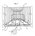
- the exemplary cargo shipping system 10 broadly includes a steam dispersion system 12, a cargo containment unit, flexitank or cargo carrier 14, and a shipping container 16.
- the shipping container 16 has a floor or bottom 46, a rear wall 48, side walls, 50, 52, a roof 54, and an entryway 56, including doors 58, 60 on either side of the entryway 56.
- the steam dispersion system 12 is positioned within an interior of the shipping container 16, and the cargo carrier 14 (shown in phantom for clarity) is positioned over the steam dispersion system 12 for reasons which are described in greater detail below.
- the steam dispersion system 12 includes a steam distribution junction or manifold 18, which is connected to a steam generator 20 by way of a supply hose 24.
- the steam generator 20 may include a pressure control regulator or valve 21 to control steam pressure, as described by example operation below.
- the manifold 18 has an input coupling 26, to which the supply hose 24 is connected.
- the manifold 18 may also include one or more distribution couplings 28, to which respective steam dispersion devices, dispersing units, or diffusers 22 are connected.
- the manifold 18 in this example is a metal pipe and the distribution couplings 28 are metal fittings, these components may be formed from other materials and may be configured in different arrangements.
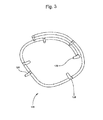
- the manifold 18 may be rubber tubing and the distribution couplings 28 may be plastic fittings. See, e.g., FIGURE 3 . There also may be fewer or additional distribution couplings 28 than the quantity shown in FIGURE 1 . Thus, the manifold 18 and couplings 28 are not limited to the exemplary arrangement shown in FIGURE 1 .
- FIGURE 1 further shows that the steam diffusers 22 have attachment ends 30 that are connected to respective receiving or connection ends 29 of the distribution couplings 28.
- each of the steam diffusers 22 has numerous apertures or vent openings from which steam is expelled into the shipping container 16.
- a permeable cloth, sheet or layer 36 may be placed over one or more of the steam diffusers 22 and between the steam diffusers 22 and the cargo carrier 14.
- the permeable sheet 36 may help prolong the life of the cargo carrier 14, particularly if the cargo carrier 14 is a flexible plastic tank, such as a SEALINER® flexitank product available from Powertex, Inc.
- the sheet 36 may protect the cargo carrier 14 from heat damage, and being permeable or porous, the sheet 36 does not entirely block release of steam into the shipping container 16, as described by example operation below.
- FIGURE 2 is a detailed view of a portion of the manifold 18 as shown in FIGURE 1 .
- one of the distribution couplings 28 of the manifold 18 is connected to one of the steam diffusers 22 by mating the attachment or receiving end 30 of the respective steam diffuser 22 to the respective connection end 29 of the distribution coupling 28.
- the receiving ends 29, 30 are screwed together, but may be twist locked together or snap-fit, one end over the other, etcetera.
- the steam diffuser 22 may be made of a coiled or spiral- or serpentine-wrapped metal that forms a plurality of apertures, gaps, spaces or vent openings 32 between each coil of metal.
- the diffuser 22 may be a continuous, metallic, helically formed device; however, the diffuser 22 could also be formed from hardened plastic and/or from separate pieces fitted together. Accordingly, when the steam generator 20 (see FIGURES 1 and 5 ) is activated, steam 34 is supplied from the manifold 18 into the steam diffuser 22 and is expelled under pressure from each of the vent openings 32 to fill the interior of the shipping container 16 with steam 34. Because the steam 34 is expressed under pressure from the steam diffuser 22 into the container 16 and is not merely circulated or pumped through the steam diffuser 22, heating occurs rapidly within the shipping container 16.
- the apertures 32 of the steam diffusers 22 shown in FIGURE 2 may be staggered and may have different sizes. Alternatively, the apertures 32 may be evenly spaced. They may be formed over various areas of the steam diffusers 22, or the apertures 32 may be formed, for instance, only along sides of the steam diffusers 22 substantially parallel to the floor 46 of the container 16 to effect a directional diffusion of the steam 34; e.g., to direct the steam 34 away from the floor 46 of the container 16. Additionally, the apertures 32 may be adjustable, e.g., changed in size manually, electronically, or elastomerically by pressure to control the flow of the steam 34.
- one or more of the apertures 32 may be opened, adjusted, or closed, as indicated by double headed arrow in the inset of FIGURE 2 , to a larger (or smaller) width, circumference, or the like as shown by element number 33 to control the flow of the steam 34 and thus the rate of temperature change within the container 16.
- steam pressure may be regulated by the pressure control regulator 21 (see FIGURES 1 and 5 ).
- the apertures 32 may be expanded elastomerically under pressure to permit more of the steam 34 to discharge from the apertures 32.
- the pressure control regulator 21 decreases steam pressure, the apertures 32 may contract to limit the flow of the steam 34 into the container 16.
- the floor 46 of the shipping container 16 may be angled.
- the sheet 36 may be a nonwoven textile to permit some of the steam 34 to condense within its fibers thereby saturating the sheet 36 with hot water. With assistance from the angled floor 46 and gravity, the sheet 36 wicks the condensed steam 34 (in the form of hot water) under the cargo carrier 14 and about the floor 46 thereby heating the floor 46 and increasing the efficiency of the steam dispersion system 12.
- the angled floor 46 may assist the hot water to weep from the shipping container 16, such as from near the entryway 56 or other openings in the shipping container 16. If the floor 46 is not angled, the sheet 36 may still wick some of the condensed steam 34 to help efficiencies of the steam dispersion system 12.
- an alternative manifold 118 may include a steam input nozzle 126 and a number of nipple-type fittings or dispersion connectors 128 having respective connection ends 129.
- the exemplary manifold 118 may be made from a flexible rubber or other elastomeric material and may be fitted with the nipple connectors 128.
- the connectors 128 may be hardened plastic or another suitably durable material for receiving attachment ends of respective steam diffusers (not shown but compare ends 30 of diffuser 22 in FIGURE 2 ).
- the diffuser attachment ends may be press-fit over the nipples 128.
- the arrangement could be reversed; e.g., the attachment ends could be formed to press-fit or snap-fit into the nipples 128. Still other connection arrangements are possible and are within the scope of the present disclosure.
- FIGURES 4 and 5 show the interior of the shipping container 16 with the cargo carrier 14 and the felt layer 36 positioned on the floor of the container 16.
- a gate assembly 38 is positioned to support the cargo carrier 14 after it is filled with a liquid cargo.
- FIGURE 5 particularly shows a rear view of the shipping container 16.
- the gate assembly 38 includes an access port 40 through which a discharge hose 42 is connected to a loading/discharge port 44 of the cargo carrier 14 (having been filled with cargo relative to FIGURE 4 ).
- the supply hose 24 is shown connected to the steam generator 20, briefly introduced above, leading through the entryway 56 of the shipping container 16 and is connected with the manifold 18 (compare FIGURE 1 ).
- the arrangement shown in FIGURE 5 provides for the steam 34 to be delivered into the manifold 18 and released into the environment of the container 16 to surround the cargo carrier 14.
- test results in FIGURE 6 show that after about 24 to about 30 hours, the cargo shipping system 10 according to one aspect of the disclosure increased a temperature of a liquid cargo nearly threefold to a nominal temperature for unloading the liquid cargo.
- a temperature of the liquid cargo in a flexitank at about 54° F in an ambient environment of about 20° F increased to about 130° F at 9 psi of steam pressure within thirty hours.
Landscapes
- Engineering & Computer Science (AREA)
- Mechanical Engineering (AREA)
- Apparatus For Disinfection Or Sterilisation (AREA)
Applications Claiming Priority (1)
| Application Number | Priority Date | Filing Date | Title |
|---|---|---|---|
| US13/075,874 US20120247067A1 (en) | 2011-03-30 | 2011-03-30 | Steam dispersion system for cargo containers |
Publications (1)
| Publication Number | Publication Date |
|---|---|
| EP2505516A1 true EP2505516A1 (de) | 2012-10-03 |
Family
ID=46027576
Family Applications (1)
| Application Number | Title | Priority Date | Filing Date |
|---|---|---|---|
| EP12161405A Withdrawn EP2505516A1 (de) | 2011-03-30 | 2012-03-27 | Dampfdispersonssystem für Frachtcontainer, Frachtsystem und Verfahren zur Beladung von Flüssigkeiten in einem Behälter damit |
Country Status (2)
| Country | Link |
|---|---|
| US (1) | US20120247067A1 (de) |
| EP (1) | EP2505516A1 (de) |
Cited By (2)
| Publication number | Priority date | Publication date | Assignee | Title |
|---|---|---|---|---|
| CN103818660A (zh) * | 2014-03-26 | 2014-05-28 | 四川宏华石油设备有限公司 | 一种柔性水罐的管汇系统 |
| EP4214087A4 (de) * | 2020-09-15 | 2024-01-31 | Likua Endustriyel Ambalaj Malzm. San. ve Tic. Ltd. Sti. | Heizeinheit |
Families Citing this family (3)
| Publication number | Priority date | Publication date | Assignee | Title |
|---|---|---|---|---|
| FR3063925B1 (fr) * | 2017-03-20 | 2020-02-07 | Thermodynamic Workshop Training - Twt | Dispositif de traitement thermique de grumes |
| CN112078986B (zh) * | 2020-09-07 | 2023-01-24 | 越海散装液体物流有限公司 | 一种集装箱蒸汽加热系统 |
| US12382944B2 (en) * | 2022-01-11 | 2025-08-12 | Ecolab Usa Inc. | Rigid fumigant barrier for shipping container door |
Citations (5)
| Publication number | Priority date | Publication date | Assignee | Title |
|---|---|---|---|---|
| US3553971A (en) * | 1967-12-19 | 1971-01-12 | Vortair Engineering Ltd | Refrigeration of mobile containers |
| JPS58112989A (ja) * | 1981-12-24 | 1983-07-05 | 新日本製鐵株式会社 | 沈降性スラリ−燃料の貯蔵方法及び貯蔵タンク |
| WO2004101397A1 (en) * | 2003-05-18 | 2004-11-25 | Mærsk Container Industri As | Temperature controlling apparatus for a container |
| JP2006056571A (ja) * | 2004-08-20 | 2006-03-02 | Arakawa Chem Ind Co Ltd | 産業コンテナ用保温カバー |
| DE202007005493U1 (de) * | 2007-04-13 | 2007-07-26 | Krenzke, Dirk | Frachtcontainer |
Family Cites Families (25)
| Publication number | Priority date | Publication date | Assignee | Title |
|---|---|---|---|---|
| US1370531A (en) * | 1916-11-11 | 1921-03-08 | Barber Asphalt Paving Co | Device for facilitating the unloading of tank-cars carrying bituminous materials |
| US1584685A (en) * | 1921-06-06 | 1926-05-11 | Hyde Ralph Manison | Regulator for steam generators |
| US2100555A (en) * | 1935-02-11 | 1937-11-30 | Cash A W Co | Steam pressure regulator |
| US2642314A (en) * | 1951-04-14 | 1953-06-16 | Crown Zellerbach Corp | Dripless steam shower pipe |
| US3384154A (en) * | 1956-08-30 | 1968-05-21 | Union Carbide Corp | Heat exchange system |
| US3554183A (en) * | 1968-10-04 | 1971-01-12 | Acf Ind Inc | Heat pipe heating system for a railway tank car or the like |
| US3940940A (en) * | 1972-08-12 | 1976-03-02 | The British Petroleum Company Limited | Protection method |
| US4129181A (en) * | 1977-02-16 | 1978-12-12 | Uop Inc. | Heat transfer surface |
| US4236672A (en) * | 1979-04-16 | 1980-12-02 | Angelus Sanitary Can Machine Company | Nozzle for steaming retortable pouches |
| US4334862A (en) * | 1980-08-26 | 1982-06-15 | Tioga Air Heaters, Inc. | Barrel warmer for drilling rigs |
| US4476788A (en) * | 1982-06-07 | 1984-10-16 | Richard Loevinger | Heated railroad tank car |
| DE8710599U1 (de) * | 1987-08-03 | 1987-09-24 | Cassens, Holger, 2000 Hamburg | Temperierbarer Tankcontainer |
| US5158363A (en) * | 1991-08-16 | 1992-10-27 | Propper Manufacturing Company, Inc. | Steam sterilization indicator |
| GB9616678D0 (en) * | 1996-08-08 | 1996-09-25 | Eaton Williams Group Ltd | Steam outlet assembly |
| WO1998014077A2 (en) * | 1996-09-23 | 1998-04-09 | Tobacco Research And Development Institute Limited | Method and apparatus for the enhancement of tobacco |
| US5755049A (en) * | 1997-07-24 | 1998-05-26 | Excelsior Belting - Equipment Co., Inc. | Thermal insulation cover set for steam and laundry press apparatus |
| US6899288B2 (en) * | 2002-01-22 | 2005-05-31 | Spraying Systems Co. | Multi-nozzle spray bar with segmented header |
| WO2005079281A2 (en) * | 2004-02-12 | 2005-09-01 | Spraying Systems Co. | Electrostatic spray assembly |
| CN1957220B (zh) * | 2004-04-23 | 2010-06-16 | 奥胡斯卡尔斯丹麦公司 | 用于提高在容器中初始处于至少部分固化状态的物质的温度的方法、设备、系统和换热器 |
| US7468497B2 (en) * | 2005-07-13 | 2008-12-23 | Cont-Asphalt Ltd. | Heatable container |
| CA2526179C (en) * | 2005-12-06 | 2007-09-18 | John Schwarz | Steam cover for de-icing and thawing surfaces and equipment |
| US20080087665A1 (en) * | 2006-10-13 | 2008-04-17 | Columbiana Boiler Company, Llc | Freight container |
| US20080257893A1 (en) * | 2007-04-19 | 2008-10-23 | Podd Stephen D | Bulk liquid transport system |
| US20090134171A1 (en) * | 2007-07-03 | 2009-05-28 | Deberardinis Nicholas W | Modular tank unit for ship, barge and rail transportation |
| US7976885B2 (en) * | 2007-10-23 | 2011-07-12 | Alkar-Rapidpak-Mp Equipment, Inc. | Anti-microbial injection for web packaging pasteurization system |
-
2011
- 2011-03-30 US US13/075,874 patent/US20120247067A1/en not_active Abandoned
-
2012
- 2012-03-27 EP EP12161405A patent/EP2505516A1/de not_active Withdrawn
Patent Citations (5)
| Publication number | Priority date | Publication date | Assignee | Title |
|---|---|---|---|---|
| US3553971A (en) * | 1967-12-19 | 1971-01-12 | Vortair Engineering Ltd | Refrigeration of mobile containers |
| JPS58112989A (ja) * | 1981-12-24 | 1983-07-05 | 新日本製鐵株式会社 | 沈降性スラリ−燃料の貯蔵方法及び貯蔵タンク |
| WO2004101397A1 (en) * | 2003-05-18 | 2004-11-25 | Mærsk Container Industri As | Temperature controlling apparatus for a container |
| JP2006056571A (ja) * | 2004-08-20 | 2006-03-02 | Arakawa Chem Ind Co Ltd | 産業コンテナ用保温カバー |
| DE202007005493U1 (de) * | 2007-04-13 | 2007-07-26 | Krenzke, Dirk | Frachtcontainer |
Cited By (3)
| Publication number | Priority date | Publication date | Assignee | Title |
|---|---|---|---|---|
| CN103818660A (zh) * | 2014-03-26 | 2014-05-28 | 四川宏华石油设备有限公司 | 一种柔性水罐的管汇系统 |
| CN103818660B (zh) * | 2014-03-26 | 2016-02-17 | 四川宏华石油设备有限公司 | 一种柔性水罐的管汇系统 |
| EP4214087A4 (de) * | 2020-09-15 | 2024-01-31 | Likua Endustriyel Ambalaj Malzm. San. ve Tic. Ltd. Sti. | Heizeinheit |
Also Published As
| Publication number | Publication date |
|---|---|
| US20120247067A1 (en) | 2012-10-04 |
Similar Documents
| Publication | Publication Date | Title |
|---|---|---|
| US20120247067A1 (en) | Steam dispersion system for cargo containers | |
| US8561921B1 (en) | Plural component mixing system | |
| TW201341294A (zh) | 熱熔物儲槽及止回閥 | |
| US5361797A (en) | Sludge pipeline lubrication system | |
| US20140261762A1 (en) | Pipeline heater | |
| US7686608B2 (en) | Apparatus and methods for distributing a substance | |
| US20050274740A1 (en) | System for dispensing viscous liquids | |
| CN106574312B (zh) | 冷却装置以及多室型热处理装置 | |
| US9702583B2 (en) | Method and apparatus for heating a stored liquid | |
| US20180272377A1 (en) | Fluid application system adapted to collect and reuse reclaimed fluid | |
| JP2014047933A (ja) | 水漏れ補修方法及び水漏れ補修装置 | |
| US20200062578A1 (en) | Mobile distribution station having auxiliary delivery system | |
| CN113924160B (zh) | 反应器系统 | |
| RU2646011C2 (ru) | Способ, система и устройство для отведения жидкости | |
| CN1957220B (zh) | 用于提高在容器中初始处于至少部分固化状态的物质的温度的方法、设备、系统和换热器 | |
| US20150369517A1 (en) | Heating liquid in portable tanks | |
| US20160201439A1 (en) | Air release assembly for use with providing heated water for well related activities | |
| CN202170786U (zh) | 油井智能加药装置 | |
| RU171203U1 (ru) | Мягкий резервуар для удобрений | |
| TW201501815A (zh) | 氣冷式熱熔傳送系統及方法 | |
| CN115770769A (zh) | 真空上料系统的在线清洗装置及真空上料系统 | |
| WO2019028311A1 (en) | DEVICE FOR INJECTING AND MIXING STEAM | |
| US6848391B1 (en) | System for coating particulate with a fluid | |
| US20150021859A1 (en) | Sealing apparatus for applying corrosion prevention compound in the gap between pipe flanges without using heat | |
| US20220120371A1 (en) | Universal pipe fitting with cleaning |
Legal Events
| Date | Code | Title | Description |
|---|---|---|---|
| PUAI | Public reference made under article 153(3) epc to a published international application that has entered the european phase |
Free format text: ORIGINAL CODE: 0009012 |
|
| AK | Designated contracting states |
Kind code of ref document: A1 Designated state(s): AL AT BE BG CH CY CZ DE DK EE ES FI FR GB GR HR HU IE IS IT LI LT LU LV MC MK MT NL NO PL PT RO RS SE SI SK SM TR |
|
| AX | Request for extension of the european patent |
Extension state: BA ME |
|
| STAA | Information on the status of an ep patent application or granted ep patent |
Free format text: STATUS: THE APPLICATION IS DEEMED TO BE WITHDRAWN |
|
| 18D | Application deemed to be withdrawn |
Effective date: 20130404 |