EP2505689A1 - Cermetbeschichtung, sprühpartikel zu ihrer formung, verfahren zur formung der cermetbeschichtung und artikel mit der beschichtung - Google Patents
Cermetbeschichtung, sprühpartikel zu ihrer formung, verfahren zur formung der cermetbeschichtung und artikel mit der beschichtung Download PDFInfo
- Publication number
- EP2505689A1 EP2505689A1 EP10833357A EP10833357A EP2505689A1 EP 2505689 A1 EP2505689 A1 EP 2505689A1 EP 10833357 A EP10833357 A EP 10833357A EP 10833357 A EP10833357 A EP 10833357A EP 2505689 A1 EP2505689 A1 EP 2505689A1
- Authority
- EP
- European Patent Office
- Prior art keywords
- powder
- cermet coating
- phase
- binder phase
- hard reinforcement
- Prior art date
- Legal status (The legal status is an assumption and is not a legal conclusion. Google has not performed a legal analysis and makes no representation as to the accuracy of the status listed.)
- Withdrawn
Links
- 239000002245 particle Substances 0.000 title claims abstract description 143
- 238000000576 coating method Methods 0.000 title claims abstract description 136
- 239000011195 cermet Substances 0.000 title claims abstract description 122
- 239000011248 coating agent Substances 0.000 title claims abstract description 115
- 238000005507 spraying Methods 0.000 title claims abstract description 94
- 238000000034 method Methods 0.000 title claims description 56
- 239000000843 powder Substances 0.000 claims abstract description 120
- 239000011230 binding agent Substances 0.000 claims abstract description 72
- 230000002787 reinforcement Effects 0.000 claims abstract description 66
- 230000003746 surface roughness Effects 0.000 claims abstract description 28
- 238000010438 heat treatment Methods 0.000 claims abstract description 3
- 239000000919 ceramic Substances 0.000 claims description 12
- 238000002844 melting Methods 0.000 claims description 12
- 230000008018 melting Effects 0.000 claims description 12
- 229910052751 metal Inorganic materials 0.000 claims description 10
- 239000002184 metal Substances 0.000 claims description 10
- QYEXBYZXHDUPRC-UHFFFAOYSA-N B#[Ti]#B Chemical compound B#[Ti]#B QYEXBYZXHDUPRC-UHFFFAOYSA-N 0.000 claims description 3
- 229910003862 HfB2 Inorganic materials 0.000 claims description 3
- 229910004533 TaB2 Inorganic materials 0.000 claims description 3
- 229910033181 TiB2 Inorganic materials 0.000 claims description 3
- ATJFFYVFTNAWJD-UHFFFAOYSA-N Tin Chemical compound [Sn] ATJFFYVFTNAWJD-UHFFFAOYSA-N 0.000 claims description 3
- 229910007948 ZrB2 Inorganic materials 0.000 claims description 3
- 229910045601 alloy Inorganic materials 0.000 claims description 3
- 239000000956 alloy Substances 0.000 claims description 3
- VWZIXVXBCBBRGP-UHFFFAOYSA-N boron;zirconium Chemical compound B#[Zr]#B VWZIXVXBCBBRGP-UHFFFAOYSA-N 0.000 claims description 3
- 229910003460 diamond Inorganic materials 0.000 claims description 3
- 239000010432 diamond Substances 0.000 claims description 3
- 150000002739 metals Chemical class 0.000 claims description 3
- 229910052759 nickel Inorganic materials 0.000 claims description 3
- 229910052718 tin Inorganic materials 0.000 claims description 3
- 229910003470 tongbaite Inorganic materials 0.000 claims description 3
- 230000010354 integration Effects 0.000 claims description 2
- 229910017083 AlN Inorganic materials 0.000 claims 1
- 239000007921 spray Substances 0.000 description 21
- 238000002485 combustion reaction Methods 0.000 description 11
- 238000002156 mixing Methods 0.000 description 10
- IJGRMHOSHXDMSA-UHFFFAOYSA-N Atomic nitrogen Chemical compound N#N IJGRMHOSHXDMSA-UHFFFAOYSA-N 0.000 description 7
- 238000000151 deposition Methods 0.000 description 6
- 239000011261 inert gas Substances 0.000 description 5
- 229910000975 Carbon steel Inorganic materials 0.000 description 4
- 239000010962 carbon steel Substances 0.000 description 4
- 230000008021 deposition Effects 0.000 description 4
- 238000010586 diagram Methods 0.000 description 4
- 239000000446 fuel Substances 0.000 description 4
- 239000007789 gas Substances 0.000 description 4
- 239000000203 mixture Substances 0.000 description 4
- 239000001301 oxygen Substances 0.000 description 4
- 229910052760 oxygen Inorganic materials 0.000 description 4
- MYMOFIZGZYHOMD-UHFFFAOYSA-N Dioxygen Chemical compound O=O MYMOFIZGZYHOMD-UHFFFAOYSA-N 0.000 description 3
- 229910009043 WC-Co Inorganic materials 0.000 description 3
- QVGXLLKOCUKJST-UHFFFAOYSA-N atomic oxygen Chemical compound [O] QVGXLLKOCUKJST-UHFFFAOYSA-N 0.000 description 3
- 238000005261 decarburization Methods 0.000 description 3
- 229910001882 dioxygen Inorganic materials 0.000 description 3
- 238000005259 measurement Methods 0.000 description 3
- 229910052757 nitrogen Inorganic materials 0.000 description 3
- 239000007787 solid Substances 0.000 description 3
- 230000015572 biosynthetic process Effects 0.000 description 2
- 238000005422 blasting Methods 0.000 description 2
- 238000006243 chemical reaction Methods 0.000 description 2
- 239000002826 coolant Substances 0.000 description 2
- 238000000354 decomposition reaction Methods 0.000 description 2
- 230000003247 decreasing effect Effects 0.000 description 2
- 238000009826 distribution Methods 0.000 description 2
- 238000002474 experimental method Methods 0.000 description 2
- 238000009689 gas atomisation Methods 0.000 description 2
- 239000008187 granular material Substances 0.000 description 2
- 239000007788 liquid Substances 0.000 description 2
- 239000011164 primary particle Substances 0.000 description 2
- 238000010298 pulverizing process Methods 0.000 description 2
- 238000007873 sieving Methods 0.000 description 2
- 238000005245 sintering Methods 0.000 description 2
- 239000002002 slurry Substances 0.000 description 2
- 229910000905 alloy phase Inorganic materials 0.000 description 1
- 239000011362 coarse particle Substances 0.000 description 1
- 230000000052 comparative effect Effects 0.000 description 1
- 150000001875 compounds Chemical class 0.000 description 1
- 230000001419 dependent effect Effects 0.000 description 1
- 230000006866 deterioration Effects 0.000 description 1
- 230000001627 detrimental effect Effects 0.000 description 1
- 229910001873 dinitrogen Inorganic materials 0.000 description 1
- 238000001493 electron microscopy Methods 0.000 description 1
- 239000003350 kerosene Substances 0.000 description 1
- 239000000463 material Substances 0.000 description 1
- 239000000155 melt Substances 0.000 description 1
- 150000001247 metal acetylides Chemical class 0.000 description 1
- 230000003647 oxidation Effects 0.000 description 1
- 238000007254 oxidation reaction Methods 0.000 description 1
- 239000011347 resin Substances 0.000 description 1
- 229920005989 resin Polymers 0.000 description 1
- 239000011163 secondary particle Substances 0.000 description 1
- 238000007751 thermal spraying Methods 0.000 description 1
Images




Classifications
-
- C—CHEMISTRY; METALLURGY
- C23—COATING METALLIC MATERIAL; COATING MATERIAL WITH METALLIC MATERIAL; CHEMICAL SURFACE TREATMENT; DIFFUSION TREATMENT OF METALLIC MATERIAL; COATING BY VACUUM EVAPORATION, BY SPUTTERING, BY ION IMPLANTATION OR BY CHEMICAL VAPOUR DEPOSITION, IN GENERAL; INHIBITING CORROSION OF METALLIC MATERIAL OR INCRUSTATION IN GENERAL
- C23C—COATING METALLIC MATERIAL; COATING MATERIAL WITH METALLIC MATERIAL; SURFACE TREATMENT OF METALLIC MATERIAL BY DIFFUSION INTO THE SURFACE, BY CHEMICAL CONVERSION OR SUBSTITUTION; COATING BY VACUUM EVAPORATION, BY SPUTTERING, BY ION IMPLANTATION OR BY CHEMICAL VAPOUR DEPOSITION, IN GENERAL
- C23C24/00—Coating starting from inorganic powder
- C23C24/02—Coating starting from inorganic powder by application of pressure only
- C23C24/04—Impact or kinetic deposition of particles
-
- Y—GENERAL TAGGING OF NEW TECHNOLOGICAL DEVELOPMENTS; GENERAL TAGGING OF CROSS-SECTIONAL TECHNOLOGIES SPANNING OVER SEVERAL SECTIONS OF THE IPC; TECHNICAL SUBJECTS COVERED BY FORMER USPC CROSS-REFERENCE ART COLLECTIONS [XRACs] AND DIGESTS
- Y10—TECHNICAL SUBJECTS COVERED BY FORMER USPC
- Y10T—TECHNICAL SUBJECTS COVERED BY FORMER US CLASSIFICATION
- Y10T428/00—Stock material or miscellaneous articles
- Y10T428/24—Structurally defined web or sheet [e.g., overall dimension, etc.]
- Y10T428/24355—Continuous and nonuniform or irregular surface on layer or component [e.g., roofing, etc.]
- Y10T428/24372—Particulate matter
- Y10T428/24413—Metal or metal compound
Definitions
- the present invention relates to a cermet coating that has a hard reinforcement phase and a binder phase, and is formed from spraying particles including a powder for a hard reinforcement phase and a powder for a binder phase.
- the invention also relates to spraying particles for forming the cermet coating, a cermet coating forming method, and a coated article.
- Patent Document 1 a method of forming a cermet coating on a base surface is known in which spraying particles having a hard reinforcement phase and a binder phase are heated and applied to a base at a supersonic velocity.
- the Vickers hardness is very poor considering the hardness of the hard reinforcement phase of the spraying particles, and does not sufficiently take advantage of the particle characteristics.
- the present invention provides a cermet coating that can take advantage of the hardness of the powder for a hard reinforcement phase more effectively.
- the invention also provides spraying particles for forming the cermet coating, a cermet coating forming method, and a coated article.
- a cermet coating of the present invention is a cermet coating having a hard reinforcement phase and a binder phase formed on a base surface by the collision of spraying particles with a base, the spraying particles including a ceramic powder as a powder for a hard reinforcement phase for forming the hard reinforcement phase of the cermet coating, and a metal powder as a powder for a binder phase for forming the binder phase of the cermet coating, wherein the cermet coating has a Vickers hardness of from 50% to less than 100% of the Vickers hardness of the powder for a hard reinforcement phase.
- the cermet coating has a surface roughness (center-line average roughness Ra) of less than 3.0.
- the spraying particles are aggregates of the powder for a hard reinforcement phase and the powder for a binder phase
- the cermet coating is formed by the integration of the powder for a hard reinforcement phase and the powder for a binder phase after the spraying particles are heated and applied onto the base at a supersonic velocity.
- the powder for a hard reinforcement phase be one or more carbide ceramics selected from WC, Cr 3 C 2 , VC, NbC, TaC, TiC, ZrC, HfC, SiC, and B 4 C, or one or more non-carbide ceramics selected from diamond, TiN, AIN, HfB 2 , ZrB 2 , TaB 2 , and TiB 2 .
- the powder for a binder phase be one or more metals selected from Ni, Cr, Co, Ti, Al, and Fe, or an alloy thereof.
- a spraying particle of the present invention is a spraying particle that includes a powder for a hard reinforcement phase and a powder for a binder phase for forming any of the cermet coatings above, wherein the powder for a binder phase accounts for not more than 25 mass% and not less than 8 mass% of the total of the spraying particle.
- the powder for a hard reinforcement phase and the powder for a binder phase form an aggregate.
- a coated article of the present invention has a base that includes any of the foregoing cermet coatings formed on a base surface.
- a cermet coating forming method of the present invention is a method for forming any of the foregoing cermet coatings, and includes: heating spraying particles that include a ceramic powder for a hard reinforcement phase for forming the hard reinforcement phase of the cermet coating, and a metal powder for a binder phase for forming the binder phase of the cermet coating; and causing the spraying particles to collide with the base at a supersonic velocity to deposit the cermet coating having a hard reinforcement phase and a binder phase.
- the spraying particles collide with the base after being heated to not less than the softening temperature and less than the melting temperature of the metallic component forming the powder for a binder phase.
- the spraying particles be aggregates of the powder for a hard reinforcement phase and the powder for a binder phase.
- the cermet coating of the present invention can take advantage of the inherent hardness of the powder for a hard reinforcement phase, and thus has a hardness about twice as large as that described in Patent Document 1, and has a very flat surface. Specifically, the cermet coating can have a surface roughness (center-line average roughness Ra) of less than 3.0. This was made possible by reducing the particle diameter of the spraying particles from that described in Patent Document 1, and by thus increasing the Vickers hardness of the cermet coating. This result was obtained rather surprisingly out of concerns about the influence of the property change caused by the melting of the heated spraying particles.
- the cermet coating, and an article coated therewith thus have a wide range of practical applications, and improved reliability.
- FIG. 1 is a cross sectional view schematically illustrating an example of a warm spray gun used to form a cermet coating by the warm spray technique.
- the warm spray gun includes a combustion chamber (9) and a supersonic nozzle (11), the former being provided with a fuel inlet (1), an oxygen gas inlet (2), and a spark plug (3).
- a mixing chamber (10) including an inert gas inlet (5) for nitrogen gas or the like is provided between the combustion chamber (9) and the supersonic nozzle (11).
- the room-temperature inert gas supplied through the inert gas inlet (5) is mixed with the combustion flame generated in the combustion chamber (9), allowing for the control of the temperature and the speed of the gas flow reaching the supersonic nozzle (11).
- the nozzle (11) at the apex portion has a feedstock supply port (6) for spraying particles (8), and a barrel (12) is attached to the tip of the feedstock supply port (6).
- the combustion chamber (9), the mixing chamber (10), the nozzle (11), and the barrel (12) are cooled by coolants (4) and (7).
- the spraying particles (8) are configured from a ceramic powder and a metal powder.
- the ceramic powder is a powder for a hard reinforcement phase for forming the hard reinforcement phase of a cermet coating (13), whereas the metal powder is a powder for a binder phase for forming the binder phase of the cermet coating (13).
- the spraying particles (8) fed through the feedstock supply port (6) are heated to a specific temperature and accelerated to a specific speed range by the high-velocity gas flow generated as the temperature-controlled combustion flame in the mixing chamber (10) expands and accelerates through the supersonic nozzle (11).
- the spraying particles (8) so heated and accelerated collide with a base (14) and deposit thereon to form the cermet coating (13) having a hard reinforcement phase and a binder phase.
- Cermet coating formation involves problems, including formation of a brittle alloy phase resulting from the melting of the hard reinforcement phase into the metallic phase (binder phase), and composition changes in the hard reinforcement phase due to decarburization reaction.
- a key to solving these problems is to maintain the spraying particles at a temperature no greater than the melting point of the metal powder for a binder phase.
- the melting point of the metallic component forming the powder for a binder phase ranges from 1,455 to 1,857°C.
- the amounts of inert gas such as nitrogen supplied into the mixing chamber (10) can be controlled to heat the spraying particles (8) to a temperature at or above the softening temperature and less than the melting point of the metallic component forming the powder for a binder phase, and to accelerate the spraying particles (8) to Mach 1 or higher.
- the spraying particles (8) are heated to a temperature at or above the softening temperature and less than the melting point of the metallic component forming the powder for a binder phase, and accelerated at a supersonic velocity equal to or greater than Mach 1.
- the melt reaction and the decomposition reaction of the spraying particles (8) can be greatly suppressed during the flight of the spraying particles (8).
- the cermet coating (13) can be densely produced on the base (14) while suppressing the melting of the hard reinforcement phase into the binder phase, or the decomposition due to decarburization.
- one or more carbides selected from carbide ceramics such as WC, Cr 3 C 2 , VC, NbC, TaC, TiC, ZrC, HfC, SiC, and B 4 C, or one or more compounds selected from non-carbide ceramics such as diamond, TiN, AIN, HfB 2 , ZrB 2 , TaB 2 , and TiB 2 are considered as a typical composition of the powder for a hard reinforcement phase forming the spraying particles.
- the powder for a binder phase forming the spraying particles one or more metals selected from Ni, Cr, Co, Ti, Al, and Fe, or an alloy of these are considered.
- a base preheat temperature range of 100 to 500°C is considered as a condition for forming a cermet coating of improved quality and for fabricating a coated member.
- the base preheat temperature is maintained at 500°C or less, in order to prevent the melting, structural changes, and oxidation of the base materials. Further, the base preheat temperature is desirably 100°C or more, in order to activate the base surface during the coating adhesion process.
- the powder for a hard reinforcement phase have a particle diameter of 0.1 to 2.0 ⁇ m, preferably 0.1 to 0.3 ⁇ m.
- the particle diameter of the powder When the particle diameter of the powder is too large, sufficient flatness may not be obtained because the large size of the hard reinforcement phase becomes a more contributing factor for the surface roughness of the cermet coating. Further, the low surface area-to-volume ratio may lower the surface energy to make adhesion difficult and facilitate rebound.
- the powder for a binder phase has a particle diameter of preferably 2 ⁇ m or less.
- the "particle diameter” is evaluated by using the Fisher technique (FSSS, Fisher Sub Sieve Sizer), or by electron microscopy.
- the Fisher technique is the technique for evaluating a particle diameter from the specific surface area of a powder by measuring the flow rate of a passing gas and a pressure drop in a test tube or the like charged with a predetermined amount of powder.
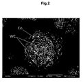
- the spraying particles are aggregates of the powder for a hard reinforcement phase and the powder for a binder phase, as shown in FIG. 2 .
- the white angular particles are the particles for a hard reinforcement phase
- the portions shown in dark gray are the particles for a binder phase.
- These powders aggregate to form a single spraying particle.
- the particles are obtained as spherical granules by the gas atomization of a slurry produced by mixing and dispersing the powder for a hard reinforcement phase and the powder for a binder phase in a liquid. The particles can then be obtained in a predetermined particle diameter distribution after preliminary sintering, pulverization, and sieving.
- the spraying particles may be used, as long as the particle size does not differ greatly from the spraying particles used in a conventionally known high-velocity flame spray technique.
- An even finer powder can be used by the warm spray technique.
- the average particle diameter is 5 to 45 ⁇ m, preferably 5 to 30 ⁇ m, more preferably 5 to 20 ⁇ m.
- the "average particle diameter" is evaluated by the laser diffraction and scattering technique.
- the laser diffraction and scattering technique is the technique for specifying the particle diameter from the intensity distribution of the scattered light from particles irradiated with a laser beam.
- the surface roughness of the cermet coating is dependent on the size of the adhering particles.
- the particle diameter of the spraying particles is excessively large, the surface roughness of the cermet coating increases.
- the excess particle diameter is also problematic, because it fails to provide a sufficient speed, and lowers the adhesion efficiency or porosity, or the temperature inside the particle becomes non-uniform, creating more variation in the internal structure of the coating, and thus producing a non-uniform coating.
- the particle diameter of the spraying particles When the particle diameter of the spraying particles is excessively small, the influence of the turbulence created by the jet flow upon colliding with the base becomes large, and sufficient adhesion efficiency cannot be obtained. Further, the excessively small particle diameter raises the particle temperature more than necessary. This is problematic because it leads to deterioration of particle properties caused by decarburization or by the melting of the hard reinforcement phase into the binder phase. Another problem is that the spraying particles adhere, which makes it difficult to supply the particles for extended time periods at a constant speed.
- the high-velocity flame spray technique often involves a phenomenon known as spitting, in which the molten powder particles adhere and deposit in a thermal spraying gun, and are spat in the form of coarse particles. This is highly detrimental to the coating quality. The warm spray technique hardly involves this problem, because it does not melt the particles.
- the relative amount of the powder for a binder phase may be appropriately set, for example, in a range of from 8 mass% to 25 mass% with respect to the total of the spraying particles, though the desirable proportions vary depending on the intended use.
- the relative amount of the powder for a binder phase may be set to 8 mass% to 10 mass%, 11 mass% to 13 mass%, 16 mass% to 18 mass%, or 23 mass% to 25 mass% with respect to the total of the spraying particles.
- the excess amount of the powder for a binder phase is problematic, because it makes the binder phase soft, and fails to provide sufficient hardness for the cermet coating.
- the cermet coating of the present invention uses the spraying particles that include a powder for a hard reinforcement phase and a powder for a binder phase, and can thus have a Vickers hardness of at least 50%, at least 60%, at least 65%, or at least 70% of the inherent Vickers hardness of the powder for a hard reinforcement phase.
- the cermet coating produced by the warm spray technique can have a higher hardness. So long as the spraying particles contain the powder for a binder phase in the content of from 8 mass% to 25 mass%, the Vickers hardness of the cermet coating tends to increase with decrease in the content of the powder for a binder phase.
- a surface roughness Ra center-line average roughness
- the lower limit of the cermet coating thickness be 100 ⁇ m or more, preferably 150 ⁇ m or more, more preferably 200 ⁇ m or more.
- the upper limit is 800 ⁇ m or less, preferably 700 ⁇ m or less, more preferably, 600 ⁇ m or less.
- Cermet coatings presented in Table 1 were produced on a base surface using the warm spray technique (WS) as examples of the cermet coating of the present invention. Cermet coatings produced by using the high-velocity flame spray technique (HVOF) are also presented as Comparative Examples.
- the fuel-to-oxygen ratio in Table 1 represents the relative ratio with respect to the stoichiometric ratio 1.0 for the complete combustion of the kerosene and oxygen supplied into the combustion chamber. The ratio is 1.0 or less in the presence of the excess oxygen.
- the combustion pressure is the value in the combustion chamber.
- the coatings produced under the conditions of Table 1 used carbon steel JIS SS400 as the base, and a powder for a hard phase WC and a powder for a binder phase Co (WC-12 to 25 weight% Co) as the sprayed cermet particles (spraying particles).
- the particle diameters and the mutual proportions of the powder for a hard phase are as presented in Table 1.
- the spraying particles are aggregates of the powder for a hard reinforcement phase and the powder for a binder phase, and were obtained after the preliminary sintering, pulverization, and sieving of the granules obtained by the gas atomization of a slurry produced by mixing and dispersing the powder for a hard reinforcement phase and the powder for a binder phase in a liquid.
- FIG. 3 is a photographic representation of a cross section of the coating obtained under the condition WS3.
- the white gray particles present over the whole surface represent the powder for a hard layer WC. It can be seen that the particles are densely dispersed in the coating.
- the cermet coatings produced by the warm spray technique using the spraying particles including the powder for a hard reinforcement phase and the powder for a binder phase had a Vickers hardness of at least 50%, at least 60%, at least 65%, or at least 70% of the inherent Vickers hardness of the powder for a hard reinforcement phase.
- the cermet coatings produced by the warm spray technique using spraying particles having an average particle diameter of 5 to 20 ⁇ m had a surface roughness of 3.0 or less, 2.5 or less, 2.0 or less, or 1.5 or less.
- WC-Co coatings were produced by using the WS or HVOF technique, using carbon steel (JIS SS400, dimensions: 100 x 50 x 5 t mm) as the base, and particles including a powder for a hard phase WC and a powder for a binder phase Co as the sprayed cermet particles (spraying particles).
- the thickness was about 300 ⁇ m.
- Table 2 represents the types of the spraying particles used, and the types of the deposition methods used to produce the cermet coatings.
- Table 3 represents the deposition conditions.
- the spraying particles are aggregates of the powder for a hard reinforcement phase and the powder for a binder phase, and were obtained in the same manner as in Example 1.
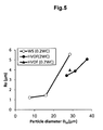
- FIG. 5 represents Ra of the cermet coating along the direction parallel to the direction of gun movement plotted against the average particle diameter of each spraying particle.
- the blank circle represents the cermet coating by the WS technique, the solid circle the cermet coating by the HVOF technique (WC particle diameter: 2 ⁇ m), and the solid triangle the cermet coating by the HVOF technique (WC particle diameter: 0.2 ⁇ m).
- the surface roughness becomes dramatically smaller with decreasing average particle diameters of the spraying particles, both in the WS technique and the HVOF technique.
- the roughness was on the order of from 1 to 6 ⁇ m, sufficiently larger than the WC particle diameter 0.2 ⁇ m of the spraying particles forming the coating.
- the surface roughness is more strongly influenced by the secondary particle diameter than by the primary particle diameter. This coincides with the result for the cermet coatings produced by the HVOF technique, in which the surface roughness hardly showed any difference between the powders that had the primary particle diameters of 0.2 ⁇ m and 2 ⁇ m ( FIG. 5 ).
- the cermet coating produced by the HVOF technique also can be obtained as a smooth coating with the use of spraying particles having a smaller average particle diameter.
- the HVOF technique it is highly probable that spitting occurs and deposition fails as in experiment number HVOF3 of Example 1 when the average particle diameter of the spraying particles is too small.
- the flame temperature can be controlled, and the spraying particles can adhere without being melted.
- the WS technique can thus deposit even spraying particles with D50 ⁇ 20 ⁇ m without causing spitting, and provide a very smooth coating with Ra ⁇ 1.5 ⁇ m.
- WC-Co coatings were produced by using the WS technique or HVOF technique, using WC-12 mass% Co spraying particles including a powder for a hard phase WC and a powder for a binder phase Co, and using a carbon steel (JIS SS400) as the base.
- Two types of spraying particles with the particle diameter ranges of 5 to 20 ⁇ m and 15 to 45 ⁇ m were used. These particles are aggregates of the powder for a hard reinforcement phase and the powder for a binder phase, and were obtained in the same manner as in Example 1.
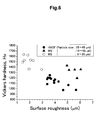
- FIG. 6 represents surface roughness Ra (center-line average roughness) and the cross section hardness (Vickers hardness, Hv) of the cermet coating.
- the cermet coating having a hardness of 1,350 to 1,650 Hv.
- the Vickers hardness of the cermet coating was at least 50% of the inherent Vickers hardness of the powder for a hard reinforcement phase.
- the cermet coating had an Ra value of 3.0 or less, 2.5 or less, 2.0 or less, or 1.5 or less; that is, the cermet coating had a smoother surface.
- WC-Co coatings were produced by using the WS technique, using WC-12 mass% Co spraying particles including a powder for a hard phase WC and a powder for a binder phase Co, and using a carbon steel (JIS SS400, dimensions: 100 x 50 x 5 t mm) as the base.
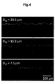
- the surface roughness of the cermet coating was measured along the direction parallel to the direction of gun movement (base longitudinal direction, x direction) and in the orthogonal direction (y direction) for every 50 to 60 ⁇ m thickness deposited on the base, and surface roughness changes were evaluated.
- the spraying particles are aggregates of the powder for a hard reinforcement phase and the powder for a binder phase, and were produced in the same manner as in Example 1.
- FIG. 7, (a) is the result of the measurement of the cermet coating surface roughness along the x direction
- FIG. 7, (b) is the result of the measurement of the cermet coating surface roughness along the y direction.
- FIG. 7, (a) and (b) also shows the surface roughness of the base surface after blasting (the base before deposition).
- the horizontal axis represents the measured distance
- the left vertical axis represents the surface profile
- the right vertical axis represents the coating thickness.
- FIG. 8 represents the surface roughness Ra (center-line average roughness) of the base after blasting, and the surface roughness Ra (center-line average roughness) of the cermet coating measured for every 50 to 60 ⁇ m thickness deposited on the base.
- the solid circle represents the surface roughness along the x direction
- the blank circle represents the surface roughness along the y direction.
- a cermet coating with an Ra of 3.0 or less was produced. It was confirmed that the Ra value was the smallest at the cermet coating thickness of about 100 to 200 ⁇ m, and gradually increased with increasing thicknesses. It was also confirmed that the cermet coating grown to the final thickness of 100 ⁇ m or more after the 50 to 60 ⁇ m stepwise deposition had a greater Ra value than the cermet coating of a 100 ⁇ m or greater thickness deposited by being continuously sprayed.
Landscapes
- Chemical & Material Sciences (AREA)
- Chemical Kinetics & Catalysis (AREA)
- Engineering & Computer Science (AREA)
- Materials Engineering (AREA)
- Mechanical Engineering (AREA)
- Metallurgy (AREA)
- Organic Chemistry (AREA)
- Coating By Spraying Or Casting (AREA)
- Other Surface Treatments For Metallic Materials (AREA)
- Powder Metallurgy (AREA)
Applications Claiming Priority (2)
| Application Number | Priority Date | Filing Date | Title |
|---|---|---|---|
| JP2009270280 | 2009-11-27 | ||
| PCT/JP2010/071185 WO2011065512A1 (ja) | 2009-11-27 | 2010-11-26 | サーメット皮膜とそれを形成する噴射用粒子、サーメット皮膜形成方法、皮膜形成品 |
Publications (2)
| Publication Number | Publication Date |
|---|---|
| EP2505689A1 true EP2505689A1 (de) | 2012-10-03 |
| EP2505689A4 EP2505689A4 (de) | 2015-09-02 |
Family
ID=44066617
Family Applications (1)
| Application Number | Title | Priority Date | Filing Date |
|---|---|---|---|
| EP10833357.6A Withdrawn EP2505689A4 (de) | 2009-11-27 | 2010-11-26 | Cermetbeschichtung, sprühpartikel zu ihrer formung, verfahren zur formung der cermetbeschichtung und artikel mit der beschichtung |
Country Status (4)
| Country | Link |
|---|---|
| US (1) | US20120308776A1 (de) |
| EP (1) | EP2505689A4 (de) |
| JP (1) | JP5769255B2 (de) |
| WO (1) | WO2011065512A1 (de) |
Cited By (2)
| Publication number | Priority date | Publication date | Assignee | Title |
|---|---|---|---|---|
| CN104789961A (zh) * | 2015-04-28 | 2015-07-22 | 山东科技大学 | 一种带有多尺度强化相涂层的耐磨斗齿及等离子熔覆方法 |
| KR101655121B1 (ko) * | 2016-02-24 | 2016-09-22 | 주식회사 썬모아 | 확대된 방열면적을 갖는 난방용 금속성기재 및 그의 제조방법 |
Families Citing this family (6)
| Publication number | Priority date | Publication date | Assignee | Title |
|---|---|---|---|---|
| US9403342B2 (en) | 2012-03-12 | 2016-08-02 | National Institute For Materials Science | Cermet coating and coated metal body having the cermet coating, method of producing cermet coating, and method of producing coated metal body |
| CN111809134A (zh) * | 2020-07-23 | 2020-10-23 | 矿冶科技集团有限公司 | 一种新型碳化钛-铁镍铬硅热喷涂粉末及其制备方法 |
| CN113667974B (zh) * | 2021-09-01 | 2022-06-03 | 燕山大学 | 钛合金表面耐磨金属-多元陶瓷复合改性涂层的制备方法 |
| CN115121789B (zh) * | 2022-08-03 | 2023-05-09 | 四川苏克流体控制设备股份有限公司 | 一种抗热震性高耐磨涂层材料及其制备方法 |
| CN117070821B (zh) * | 2023-08-16 | 2024-03-29 | 中国科学院兰州化学物理研究所 | 一种WC-Co金属陶瓷颗粒梯度增强铜基耐磨涂层及其制备方法 |
| CN117125954B (zh) * | 2023-08-28 | 2025-06-27 | 商丘中电环保发电有限公司 | 一种锅炉水冷壁的自蔓延防腐耐磨涂层的制备方法 |
Family Cites Families (10)
| Publication number | Priority date | Publication date | Assignee | Title |
|---|---|---|---|---|
| JPH0714525B2 (ja) * | 1987-09-30 | 1995-02-22 | ト−カロ株式会社 | 軟質非鉄金属板搬送用ロール |
| JP2991977B2 (ja) * | 1996-10-04 | 1999-12-20 | トーカロ株式会社 | 電気めっき用コンダクターロールおよびその製造方法 |
| JP3952252B2 (ja) * | 2001-01-25 | 2007-08-01 | 株式会社フジミインコーポレーテッド | 溶射用粉末およびそれを用いた高速フレーム溶射方法 |
| KR100515608B1 (ko) * | 2003-12-24 | 2005-09-16 | 재단법인 포항산업과학연구원 | 분말 예열 장치가 구비된 저온 스프레이 장치 |
| WO2006034054A1 (en) * | 2004-09-16 | 2006-03-30 | Belashchenko Vladimir E | Deposition system, method and materials for composite coatings |
| JP4885445B2 (ja) * | 2004-12-21 | 2012-02-29 | 株式会社フジミインコーポレーテッド | 溶射用粉末 |
| KR100802328B1 (ko) * | 2005-04-07 | 2008-02-13 | 주식회사 솔믹스 | 내마모성 금속기지 복합체 코팅층 형성방법 및 이를이용하여 제조된 코팅층 |
| KR100792190B1 (ko) * | 2005-04-19 | 2008-01-07 | 재단법인서울대학교산학협력재단 | 유심구조가 없는 고용체 분말, 그 제조 방법, 상기 고용체분말을 포함하는 서멧트용 분말, 그 제조 방법, 상기고용체 분말 및 서멧트용 분말을 이용한 유심구조가 없는세라믹스 소결체 및 서멧트 |
| JP5013364B2 (ja) * | 2006-09-12 | 2012-08-29 | 独立行政法人物質・材料研究機構 | サーメット皮膜形成方法とそれにより得られたサーメット被覆部材 |
| US7892652B2 (en) * | 2007-03-13 | 2011-02-22 | United Technologies Corporation | Low stress metallic based coating |
-
2010
- 2010-11-26 WO PCT/JP2010/071185 patent/WO2011065512A1/ja not_active Ceased
- 2010-11-26 JP JP2011543337A patent/JP5769255B2/ja not_active Expired - Fee Related
- 2010-11-26 US US13/512,080 patent/US20120308776A1/en not_active Abandoned
- 2010-11-26 EP EP10833357.6A patent/EP2505689A4/de not_active Withdrawn
Non-Patent Citations (1)
| Title |
|---|
| See references of WO2011065512A1 * |
Cited By (3)
| Publication number | Priority date | Publication date | Assignee | Title |
|---|---|---|---|---|
| CN104789961A (zh) * | 2015-04-28 | 2015-07-22 | 山东科技大学 | 一种带有多尺度强化相涂层的耐磨斗齿及等离子熔覆方法 |
| CN104789961B (zh) * | 2015-04-28 | 2017-03-15 | 山东科技大学 | 一种带有多尺度强化相涂层的耐磨斗齿及等离子熔覆方法 |
| KR101655121B1 (ko) * | 2016-02-24 | 2016-09-22 | 주식회사 썬모아 | 확대된 방열면적을 갖는 난방용 금속성기재 및 그의 제조방법 |
Also Published As
| Publication number | Publication date |
|---|---|
| EP2505689A4 (de) | 2015-09-02 |
| JP5769255B2 (ja) | 2015-08-26 |
| JPWO2011065512A1 (ja) | 2013-04-18 |
| WO2011065512A1 (ja) | 2011-06-03 |
| US20120308776A1 (en) | 2012-12-06 |
Similar Documents
| Publication | Publication Date | Title |
|---|---|---|
| US20120308776A1 (en) | Cermet coating, spraying particles for forming same, method for forming cermet coating, and coated article | |
| EP1801248B1 (de) | Verschleißfeste reibungsarme Beschichtungszusammensetzung und Verfahren zur Beschichtung | |
| US7670406B2 (en) | Deposition system, method and materials for composite coatings | |
| Marple et al. | Thermal spraying of nanostructured cermet coatings | |
| US6641917B2 (en) | Spray powder and method for its production | |
| EP1485220B1 (de) | Korrosionsfestes pulver und korrosionsfeste überzüge | |
| Li et al. | Effect of solid carbide particle size on deposition behaviour, microstructure and wear performance of HVOF cermet coatings | |
| US9394598B2 (en) | Powder for thermal spraying and process for formation of sprayed coating | |
| TWI415972B (zh) | Spray powder and spray spray film | |
| US20130251910A1 (en) | Amorphous-nanocrystalline-microcrystalline coatings and methods of production thereof | |
| MX2009002908A (es) | Polvo metalico. | |
| DE102014211366A1 (de) | Verfahren zur Erzeugung einer Oxidationsschutzschicht für einen Kolben zum Einsatz in Brennkraftmaschinen und Kolben mit einer Oxidationsschutzschicht | |
| US20120042807A1 (en) | Powder for thermal spraying and method for forming thermal-spray deposit | |
| RU2038411C1 (ru) | Способ получения покрытия | |
| EP3137643B1 (de) | Titankarbiddeckschicht und verfahren zur herstellung davon | |
| Luo et al. | Micro-nanostructured cermet coatings | |
| US20060134343A1 (en) | Thermal spraying powder, thermal spraying method, and method for forming thermal spray coating | |
| WO2008014801A1 (en) | A method for deposition of dispersion-strengthened coatings and composite electrode material for deposition of such coatings | |
| JP2012112012A (ja) | Hvaf溶射用粉末及び溶射皮膜の形成方法 | |
| JP6694817B2 (ja) | 塗装材料 | |
| JP3410025B2 (ja) | 炭化物サーメット溶射被覆部材およびその部材の製造方法 | |
| JP7321356B2 (ja) | 溶融金属浴用部材 | |
| CN107206513A (zh) | 表面包覆切削工具 | |
| KR20220031447A (ko) | 코팅체 및 코팅체 제조방법 | |
| EP4506478A1 (de) | Legierung, legierungspulver, legierungselement und verbundelement |
Legal Events
| Date | Code | Title | Description |
|---|---|---|---|
| PUAI | Public reference made under article 153(3) epc to a published international application that has entered the european phase |
Free format text: ORIGINAL CODE: 0009012 |
|
| 17P | Request for examination filed |
Effective date: 20120523 |
|
| AK | Designated contracting states |
Kind code of ref document: A1 Designated state(s): AL AT BE BG CH CY CZ DE DK EE ES FI FR GB GR HR HU IE IS IT LI LT LU LV MC MK MT NL NO PL PT RO RS SE SI SK SM TR |
|
| DAX | Request for extension of the european patent (deleted) | ||
| RA4 | Supplementary search report drawn up and despatched (corrected) |
Effective date: 20150730 |
|
| RIC1 | Information provided on ipc code assigned before grant |
Ipc: C23C 4/06 20060101ALI20150724BHEP Ipc: C23C 4/12 20060101ALI20150724BHEP Ipc: C23C 24/04 20060101AFI20150724BHEP Ipc: C23C 4/10 20060101ALI20150724BHEP Ipc: C23C 24/08 20060101ALI20150724BHEP |
|
| STAA | Information on the status of an ep patent application or granted ep patent |
Free format text: STATUS: EXAMINATION IS IN PROGRESS |
|
| 17Q | First examination report despatched |
Effective date: 20180207 |
|
| STAA | Information on the status of an ep patent application or granted ep patent |
Free format text: STATUS: THE APPLICATION IS DEEMED TO BE WITHDRAWN |
|
| 18D | Application deemed to be withdrawn |
Effective date: 20180619 |