EP2505778B1 - Luftmotor und elektrostatische beschichtungsvorrichtung - Google Patents
Luftmotor und elektrostatische beschichtungsvorrichtung Download PDFInfo
- Publication number
- EP2505778B1 EP2505778B1 EP11845128.5A EP11845128A EP2505778B1 EP 2505778 B1 EP2505778 B1 EP 2505778B1 EP 11845128 A EP11845128 A EP 11845128A EP 2505778 B1 EP2505778 B1 EP 2505778B1
- Authority
- EP
- European Patent Office
- Prior art keywords
- air
- nozzle
- bearings
- turbine
- impeller
- Prior art date
- Legal status (The legal status is an assumption and is not a legal conclusion. Google has not performed a legal analysis and makes no representation as to the accuracy of the status listed.)
- Active
Links
Images



Classifications
-
- F—MECHANICAL ENGINEERING; LIGHTING; HEATING; WEAPONS; BLASTING
- F01—MACHINES OR ENGINES IN GENERAL; ENGINE PLANTS IN GENERAL; STEAM ENGINES
- F01D—NON-POSITIVE DISPLACEMENT MACHINES OR ENGINES, e.g. STEAM TURBINES
- F01D1/00—Non-positive-displacement machines or engines, e.g. steam turbines
- F01D1/02—Non-positive-displacement machines or engines, e.g. steam turbines with stationary working-fluid guiding means and bladed or like rotor, e.g. multi-bladed impulse steam turbines
- F01D1/026—Impact turbines with buckets, i.e. impulse turbines, e.g. Pelton turbines
-
- F—MECHANICAL ENGINEERING; LIGHTING; HEATING; WEAPONS; BLASTING
- F01—MACHINES OR ENGINES IN GENERAL; ENGINE PLANTS IN GENERAL; STEAM ENGINES
- F01D—NON-POSITIVE DISPLACEMENT MACHINES OR ENGINES, e.g. STEAM TURBINES
- F01D1/00—Non-positive-displacement machines or engines, e.g. steam turbines
- F01D1/02—Non-positive-displacement machines or engines, e.g. steam turbines with stationary working-fluid guiding means and bladed or like rotor, e.g. multi-bladed impulse steam turbines
- F01D1/023—Non-positive-displacement machines or engines, e.g. steam turbines with stationary working-fluid guiding means and bladed or like rotor, e.g. multi-bladed impulse steam turbines the working-fluid being divided into several separate flows ; several separate fluid flows being united in a single flow; the machine or engine having provision for two or more different possible fluid flow paths
-
- B—PERFORMING OPERATIONS; TRANSPORTING
- B05—SPRAYING OR ATOMISING IN GENERAL; APPLYING FLUENT MATERIALS TO SURFACES, IN GENERAL
- B05B—SPRAYING APPARATUS; ATOMISING APPARATUS; NOZZLES
- B05B3/00—Spraying or sprinkling apparatus with moving outlet elements or moving deflecting elements
- B05B3/002—Spraying or sprinkling apparatus with moving outlet elements or moving deflecting elements comprising a moving member supported by a fluid cushion
-
- B—PERFORMING OPERATIONS; TRANSPORTING
- B05—SPRAYING OR ATOMISING IN GENERAL; APPLYING FLUENT MATERIALS TO SURFACES, IN GENERAL
- B05B—SPRAYING APPARATUS; ATOMISING APPARATUS; NOZZLES
- B05B3/00—Spraying or sprinkling apparatus with moving outlet elements or moving deflecting elements
- B05B3/003—Spraying or sprinkling apparatus with moving outlet elements or moving deflecting elements with braking means, e.g. friction rings designed to provide a substantially constant revolution speed
-
- B—PERFORMING OPERATIONS; TRANSPORTING
- B05—SPRAYING OR ATOMISING IN GENERAL; APPLYING FLUENT MATERIALS TO SURFACES, IN GENERAL
- B05B—SPRAYING APPARATUS; ATOMISING APPARATUS; NOZZLES
- B05B5/00—Electrostatic spraying apparatus; Spraying apparatus with means for charging the spray electrically; Apparatus for spraying liquids or other fluent materials by other electric means
- B05B5/025—Discharge apparatus, e.g. electrostatic spray guns
- B05B5/03—Discharge apparatus, e.g. electrostatic spray guns characterised by the use of gas, e.g. electrostatically assisted pneumatic spraying
-
- B—PERFORMING OPERATIONS; TRANSPORTING
- B05—SPRAYING OR ATOMISING IN GENERAL; APPLYING FLUENT MATERIALS TO SURFACES, IN GENERAL
- B05B—SPRAYING APPARATUS; ATOMISING APPARATUS; NOZZLES
- B05B5/00—Electrostatic spraying apparatus; Spraying apparatus with means for charging the spray electrically; Apparatus for spraying liquids or other fluent materials by other electric means
- B05B5/025—Discharge apparatus, e.g. electrostatic spray guns
- B05B5/04—Discharge apparatus, e.g. electrostatic spray guns characterised by having rotary outlet or deflecting elements, i.e. spraying being also effected by centrifugal forces
- B05B5/0415—Driving means; Parts thereof, e.g. turbine, shaft, bearings
-
- F—MECHANICAL ENGINEERING; LIGHTING; HEATING; WEAPONS; BLASTING
- F01—MACHINES OR ENGINES IN GENERAL; ENGINE PLANTS IN GENERAL; STEAM ENGINES
- F01D—NON-POSITIVE DISPLACEMENT MACHINES OR ENGINES, e.g. STEAM TURBINES
- F01D1/00—Non-positive-displacement machines or engines, e.g. steam turbines
- F01D1/02—Non-positive-displacement machines or engines, e.g. steam turbines with stationary working-fluid guiding means and bladed or like rotor, e.g. multi-bladed impulse steam turbines
- F01D1/06—Non-positive-displacement machines or engines, e.g. steam turbines with stationary working-fluid guiding means and bladed or like rotor, e.g. multi-bladed impulse steam turbines traversed by the working-fluid substantially radially
Definitions
- the present invention relates to an air motor mounted on a spindle device that is used in an electric painting process, or on a drive member of a spindle system for a machine tool, which uses small tools in diameter needed for high velocity revolution, for example, and an electric painting device..
- the air motor is an engine for rotating a main shaft by having the main shaft supported by static pressure gas bearings, and ejecting a gas such as compressed air toward an impeller (rotor blade) from a nozzle (holes and tubes), and is widely used, mounted on electric painting devices, high-precision machine tools, and similar devices.
- a gas such as compressed air
- rotor blade rotor blade
- nozzle holes and tubes
- Various modifications of conventional devices have been made so as to improve rotation efficiency, and various motor configurations as concrete examples thereof are well-known (See Patent Document 1 and Patent Document 2).
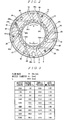
- FIGS. 1 and 2 illustrate a configuration of an air motor (spindle device with air turbine) mounted on an electrostatic spray gun of an electric painting device as a configuration example of such an air motor.
- This air motor includes a hollow main shaft 2, which extends in an approximately right circular tube form from a base to a tip (from right end to left end in FIG. 1 ), and an impeller 4, which is arranged on the base of the main shaft 2 concentric therewith.
- the impeller 4 includes a annular portion 6, which is a larger flat plate in diameter than the main shaft 2 and is positioned and fixed to the base of the main shaft 2 by a fastening member or the like, and an impeller main body 8, which is a short cylinder that is larger in diameter than the main shaft and smaller in diameter than the annular portion 6 and is fixed on an axial side (right side in FIG. 1 ) of the annular portion 6.
- Multiple turbine blades 10 are formed across the entire impeller main body 8 at equal intervals along the circumference thereof.
- Each of the turbine blades 10 is structured with the same form so as to have the same gradient (for example, forward tilting in normal rotative direction (right rotative direction C in FIG. 2 ) of the impeller 4) in the same rotative direction.
- the main shaft 2 and the impeller 4 making such a structure are rotatably supported by predetermined bearings (radial static pressure gas bearings 14 and axial static pressure gas bearings 16) in a housing 12, respectively.
- a bearing main unit 18 of the radial static pressure gas bearings 14 is made of a porous material in cylindrical form, fixed at a central portion along the axis inside of the housing 12, and arranged such that the inner periphery thereof is arranged facing a central portion along the axis of the external surface of the main shaft 2 at a slight gap therefrom.
- the axial static pressure gas bearings 16 are structured such that a bearing main unit 22 thereof made of a porous material is ring-shaped and has an oblong cross section, fixed to the base (right end in FIG. 1 ) of the housing 12, and is arranged such that an axial side (right side in FIG. 1 ) faces the circumference of the opposite side (left side) to the fixing side of the annular portion 6, which comprises the impeller 4, for the impeller main body 8.
- the air supply channel 20 extends to the external surface of the bearing main unit 22 of the axial static pressure gas bearings 16 so as to also supply compressed air to spaces from a side of the annular portion 6 of the impeller 4 via the periphery of the bearing main unit 22.
- the compressed air continuously supplied to the spaces through the air supply channel 20 is successively exhausted to the exterior space via exhaust holes 24, which are provided within the bearing main body 18 of the radial static pressure gas bearings 14, an exhaust channel 26, which is provided within the housing 12, and spaces within the housing 12.
- the impeller 4 and the main shaft 2 to which the impeller 4 is fixed should be aligned along the axis by other axial static pressure gas bearings (not illustrated in the drawing), which are additional ones to the axial static pressure gas bearings 16, rotatably supporting the opposite side (i.e., the fixing side for the impeller main body 8 (right side in FIG. 1 )) to the supporting side of the annular portion 6, which is supported by the axial static pressure gas bearings 16.
- the impeller 4 is arranged in the housing 12 such that the inner periphery on the base side (right end side in FIG.. 1 ) and the outer periphery of the impeller main body 8 may face each other all around.
- the base side inner periphery of the housing 12 is positioned radially outward from the impeller main unit 8.
- turbine air nozzle holes 28 which are formed at predetermined intervals along the circumference toward the periphery of the impeller main body 8, are formed on the base side of the housing 12, which is positioned radially outward from the impeller main body 8.. These turbine air nozzle holes 28 are formed such that all centers thereof are positioned within a virtual plane orthogonal to a central axis of the housing 12, and tilt at the same angle with respect to the radial direction of the housing 12 (in other words, they forward-tilt in the normal rotative direction (right rotative direction C in FIG.
- turbine air nozzle holes 28 continue to a turbine air supply channel 30, which has an opening 28u on an upstream end (compressed air (turbine air) supply source side) formed all around near the base side periphery of the housing 12, and the turbine air supply channel 30 continues to a turbine air supply opening 32, which opens to the base (right end in FIG. 1 ) of the housing 12 at one place along the circumference.
- the respective turbine air nozzle holes 28 have downstream ends (turbine air spray inlets) 28d open to the base side inner periphery of the housing 12. In other words, the downstream ends (turbine air spray inlets) 28d of the respective turbine air nozzle holes 28 are formed closely facing the multiple turbine blades 10 formed on the external surface of the impeller main unit 8.
- a brake air nozzle hole 34 is formed in the housing 12, opening to the periphery of the impeller main body 8 such that it does not overlap with the above multiple turbine air nozzle holes 28 on the base side.
- the brake air nozzle hole 34 is formed such that the center thereof is positioned within a virtual plane having the same central axis as the turbine air nozzle holes 28 (i.e., within a virtual plane orthogonal to the central axis of the housing 12 that is the same as those of the turbine air nozzle holes 28) and tilts at a predetermined angle (approximately the same angle as the turbine air nozzle holes 28) in the opposite direction than the turbine air nozzle holes 28 with respect to the radial direction of the housing 12 (in other words, forward-tilts in reverse rotative direction of the impeller 4 (left rotative direction A in FIG.
- the brake air nozzle hole 34 has an upstream end (brake air supply source side) opening 34u continuing to a brake air supply opening 36, which opens to the base (right end in FIG. 1 ) of the housing 12, and a downstream end (brake air spray inlet) 34d opening on the base side inner periphery of the housing 12
- the downstream end (brake air spray inlet) 34d of the brake air nozzle hole 34 is formed closely facing the multiple turbine blades 10 formed on the external surface of the impeller main body 8.
- a circular rotation detecting sensor 38 is arranged on the base side of the housing 12 such that the inner periphery of the bearing main unit 22 of the axial static pressure gas bearings 16 and the other axial side (left side in FIG. 1 ) of the impeller main body 8 may face each other with a predetermined distance therebetween.
- the rotation detecting sensor 38 includes a detector (right side portion in FIG.. 1 ) capable of facing the other axial side of the impeller main body 8 and a to-be-detected unit (encoder) on the other side of the impeller main unit 8.
- the rotational state (rotation speed, rotative direction, and the like) of the impeller 4 is detected by detecting and measuring positional change of the to-be-detected unit (encoder) using the detector.
- a magnet for example is employed as the rotation detecting sensor 38 in the air motor illustrated in FIG. 1 .
- the axial bearing 16 is provided only on the output side of the rotary movement, as shown in FIG. 1 , which may allow the main shaft 2, the impeller 4, and the impeller main body 8 to slip out to the opposite side to the output side (opposite direction than the output side of the rotary movement) of the rotary movement, Employment of the magnet for the rotation detecting sensor 38 thereby allows attraction to the main shaft 2 so as to reduce the chance of the main shaft 2, the impeller 4, and the impeller main body 8 from slipping out to the opposite side to the output side of the rotary movement.
- function and arranging position may be appropriately selected according to purpose.
- installation of the axial bearings 16 on either side of the impeller 4 allows a structure not employing a magnet as the rotation detecting sensor 38.
- the air motor spindle device with air turbine
- the main shaft 2 and the impeller 4 are rotatably supported on the housing 12 by the radial static gas bearings 14 and the axial static gas bearings 16, respectively.
- compressed air turbine air
- the supplied compressed air turbine air
- the supplied compressed air is blown onto the multiple turbine blades 10 formed on the periphery of the impeller main unit 8 from the downstream ends (turbine air spray inlets) 28d of the respective turbine air nozzle holes 28.
- the turbine blades 10 are continuously depressed in their tilt direction, namely normal rotative direction (right rotative direction C in FIG. 2 ) of the impeller 4, rotating the impeller 4 and the main shaft 2 in the normal rotative direction at a predetermined rotation speed (e..g.., several tens of thousands rpm).
- a coating material is then supplied into a predetermined cup (not illustrated in the drawing) via a coating material supply-pipe (not illustrated in the drawing) inserted inside of the main axis 2 in this state.
- the cup is fixed to a portion of the front end (left end in FIG.. 1 ) of the main shaft 2 that protrudes (is exposed) to the outside of the housing 12, and is negatively charged.
- the coating material supplied to the cup is made into ion microparticles within the cup that rotates at a high speed along with the main shaft 2.
- the coating material made into ion microparticles is thrown toward a positively-charged surface to be coated utilizing electrostatic attraction and adhered on that surface.
- the compressed air (turbine air) blown onto the respective turbine blades 10 is exhausted out into the outside space from an opening on the base side of a circular space 40 between the inner periphery on the base side of the housing 12 and the outer periphery of the impeller main body 8 via an exhaust channel (not illustrated in the drawing) connecting to the opening.
- driving force of the air motor is dependant on momentum of the jet flow from the nozzle that hits a turbine, namely momentum of the compressed air (turbine air) ejected from the downstream ends (turbine air spray inlets) 28d of the turbine air nozzle holes 28 to be blown onto the multiple turbine blades 10 that are formed on the periphery of the impeller 4 (more specifically, the impeller main body 8).
- the driving force (torque) of the impeller 4 sprayed with the compressed air (turbine air) at that time is calculated using the following Equation 1 (See Non-patent Document 1).
- Equation 1 T denotes torque of the turbine (the impeller 4), F denotes momentum (driving force) of jet flow (ejected compressed air from the turbine air nozzle holes 28) from the nozzle, R denotes radius of the turbine (the impeller 4 sprayed with the ejected compressed air) on which the jet flow impacts, m denotes mass (where mass flow rate x ⁇ t) of the jet flow (ejected compressed air), V denotes flow velocity of the jet flow (the ejected compressed air), and Vt denotes circumferential velocity (where V t is 2nRN and N denotes motor rotation frequency) at the region (region of the impeller 4 on which the jet flow impacts) impacted by the jet flow.
- the flow velocity of the gas flowing into the nozzle (flow velocity of the compressed air (turbine air) immediately after being supplied to the turbine air nozzle holes 28 from the turbine air supply channel 30 via the upstream end openings 28u or inlet to the turbine air nozzle holes 28; hereafter it is referred to as inlet flow velocity) is not acoustic velocity even under choked conditions such that maximum velocity as jet flow is attained in the nozzle, and is calculated using the following Equation 2.
- Equation 2 v e denotes inlet flow velocity in the nozzle (the turbine air nozzle holes 28) in a choked state, a 0 denotes acoustic velocity, and k denotes specific heat ratio of compressed air (turbine air).
- mass (namely, maximum value of mass flow rate) of the jet flow (ejected compressed air) in the above choked state is calculated using the following Equation 3.
- Equation 3 mass of the jet flow (ejected compressed air) in the above choked state
- ⁇ 0 denotes density of the compressed air (turbine air) on the upstream side
- a e denotes inlet area of the nozzle (the turbine air nozzle holes 28).
- the inlet flow velocity (v e ) (approximately 313 m/s) of the compressed air (turbine air) in the nozzle (the turbine air nozzle holes 28) in a choked state should be raised to the acoustic velocity (340 m/s).
- the acoustic velocity (340 m/s) For example, expanding the compressed air (turbine air) using pressure drop in the compressed air by fluid friction (inner periphery of the turbine air nozzle holes 28) of the nozzle makes it possible to increase the inlet flow velocity (v e )
- the maximum velocity is acoustic velocity (340 m/s)
- Equation 6 (see Non-patent Document 2) given below when M 1 is v e / a 0 .
- r h denotes hydraulic radius (inner radius in the case of round holes or circular tubes, cross-sectional area A in the case of square holes and square tubes, and is defined by 2 x A /C in the case where circumference length is C)
- c f denotes viscous friction factor of the wall (inner periphery of the turbine air nozzle holes 28) of the nozzle (holes and tubes).
- Equation 6 holds true even when the cross-sectional shape of the nozzle (the turbine air nozzle holes 28) is other shapes than round, such as square.
- L r h 2 c f 1 ⁇ M 1 2 kM 1 2 + k + 1 2 ⁇ k ln k + 1 M 1 2 2 + k ⁇ 1 M 1 2
- the inlet flow velocity (v e ) of the compressed air in the nozzle (holes and tubes) in a choked state should be raised to be close to the acoustic velocity (340 m/s).
- the nozzle the turbine air nozzle holes 28
- it is considered effective to set the length of the nozzle to at least the value (namely L) calculated by Equation 6 in accordance with the inlet flow velocity (v e ) in the nozzle calculated from the maximum torque required by the air motor, diameter size (hydraulic radius) (r h ) of the nozzle, and supply source conditions for the compressed air (specifically, supply pressure (p 0 ) or supply flow rate).
- the present invention has been devised so as to resolve such problems, and an object thereof is to provide an air motor improving drive efficiency by setting length of a nozzle based on compressed air inlet flow velocity in the nozzle (holes and tubes), which supplies compressed air to be blown onto turbine blades of an impeller, diameter size (hydraulic radius) of the nozzle, and supply conditions for the compressed air (supply pressure or supply flow rate).
- an air motor includes a housing, a main shaft inserted inside of the housing, an impeller fixed concentrically with the main shaft to an inserted portion of the main shaft inside of the housing and having multiple turbine blades formed on the outer periphery, bearings for rotatably supporting the main shaft and the impeller in the housing, and at least one nozzle having a tubular or hole-shaped channel for ejecting compressed air to the respective turbine blades for rotating the impeller along the circumference.
- the channel of the nozzle should be set to the dimension of the calculated value of L or greater, the nozzle has a length set to a dimension of five times the calculated value of L or greater at that time.
- bearings are preferably static pressure gas bearings.
- At least bearings on one end side are preferably structured as ceramic roller bearings.
- roller bearings preferably include a raceway ring on one side mounted on the housing, and a raceway ring on the other side mounted on a spindle facing the raceway ring on the one side, and a plurality of rolling elements incorporated between these raceway ring, where either the bearing rings or the rolling elements or all of them are made of ceramics.
- bearing rings or the rolling elements or all of them are made of non-conducting ceramics.
- the bearing rings and the rolling elements are made of conducting ceramics ..
- an electric painting device of the present invention includes the air motor of any of the above configurations.
- an air motor improving drive efficiency by setting length (nozzle length) of a nozzle based on compressed air inlet flow velocity in the nozzle, which supplies compressed air to be blown onto turbine blades of an impeller, diameter size (hydraulic radius) of the nozzle, and supply conditions for the compressed air (supply pressure or supply flow rate), and an electric painting device may be implemented.
- Embodiments including an air motor of the present invention will now be described with reference to the attached drawings.
- the air motor according to this embodiment may be assumed to be mounted on a spindle device that is used in an electric painting process, or on a drive member of a main spindle system for a machine tool, that uses small tools in diameter needed for high velocity revolution, for example, the mounting instrument is not limited thereto..
- the air motor according to this embodiment limits length of the nozzle that constitutes the air motor to a dimension within a predetermined range, and there is no problem for the basic configuration of the air motor other than the nozzle to be that of a well-known air motor .. Therefore, the configuration ( FIGS. 1 and 2 ) of the air motor (spindle device with air turbine) mounted on an electrostatic spray gun of an electric painting device as described above is assumed as a motor configuration example, where this embodiment is described on the premise of this motor configuration..
- the air motor includes the housing 12, a main shaft 2, which is inserted inside of the housing 12, the impeller 4, which is fixed to a portion of the main shaft 2 inserted inside of the housing 12 concentrically with the main axis 2 and has the multiple turbine blades 10 formed on the outer periphery, static pressure gas bearings (the radial static pressure gas bearings 14 and the axial static pressure gas bearings 16) for rotatably supporting the main axis 2 and the impeller 4 in the housing 12, and at least one of nozzles 28 and 34 having tubular or hole-shaped channels for ejecting compressed air to the respective turbine blades 10 for rotating the impeller 4 along the circumference.
- static pressure gas bearings the radial static pressure gas bearings 14 and the axial static pressure gas bearings 16
- the housing 12, the main axis 2, the impeller 4, and the static pressure gas bearings are not particularly limited to the illustrated configuration of the drawings, and may be modified appropriately in accordance with intended purpose and use conditions of the air motor.
- configuration of the housing 12 and the main shaft 2, size and number of the impeller 4, configuration and number of the turbine blades 10 formed on the impeller main body 8 of the impeller 4, arranging position and number of the static pressure gas bearings 14 and the axial static pressure gas bearings 16 need to be respectively set arbitrarily in accordance with intended purpose and use conditions of the air motor.
- the turbine air nozzle holes 28 are formed such that all centers thereof are positioned within the same virtual plane (hereafter referred to as turbine air nozzle hole formation plane) that is orthogonal to the central axis of the housing 12, and tilt (forward-tilt in the normal rotative direction (right rotative direction C in FIG. 2 ) of the impeller 4) at the same angle with respect to the radial direction of the housing 12.
- turbine air nozzle hole formation plane that is orthogonal to as turbine air nozzle hole formation plane
- the turbine air nozzle holes 28 are formed on the base side of the housing 12 as holes opening to the outer periphery of the impeller 4 (impeller main body 8), and include hole-shaped channels for spraying compressed air (turbine air) to the respective turbine blades 10 so as for the impeller 4 to rotate along the circumference (normal rotative direction C).
- the brake air nozzle hole 34 is formed such that the center thereof is positioned within the same plane as the turbine air nozzle hole formation plane, and tilt (forward-tilt in reverse rotative direction (left rotative direction A in FIG. 2 ) of the impeller 4) at a predetermined angle (for example, approximately the same angle as the turbine air nozzle holes 28) in the opposite direction than the turbine air nozzle holes 28 with respect to the radial direction of the housing 12.
- the brake air nozzle hole 34 is formed on the base side of the housing 12 as holes opening to the outer periphery of the impeller 4 (impeller main body 8) so as not to overlap with the turbine air nozzle holes 28, and includes a hole-shaped channel for spraying compressed air (brake air) to the respective turbine blades 10 so as for the impeller 4 to rotate along the circumference (reverse rotative direction A).
- the turbine air nozzle holes 28 and the brake air nozzle hole 34 are respectively configured as a nozzle of the air motor..
- FIGS. 1 and 2 illustrate a configuration of an air motor in which six of the turbine air nozzle holes 28 are formed such that centers thereof are positioned and open in the same turbine air nozzle formation plane at equal intervals on the base side of the housing 12 toward the outer periphery of the impeller 4 (impeller main body 8), a configuration in which the same or a different number of turbine air nozzle holes 28 are formed such that the centers thereof are positioned in multiple turbine air nozzle hole formation planes is possible.
- FIGS. 1 and 2 illustrate a configuration of an air motor in which six of the turbine air nozzle holes 28 are formed such that centers thereof are positioned and open in the same turbine air nozzle formation plane at equal intervals on the base side of the housing 12 toward the outer periphery of the impeller 4 (impeller main body 8)
- a configuration in which the same or a different number of turbine air nozzle holes 28 are formed such that the centers thereof are positioned in multiple turbine air nozzle hole formation planes is possible.
- FIGS. 1 and 2 illustrate a configuration
- FIGS. 1 and 2 illustrate a configuration of an air motor in which only a single brake air nozzle hole 34 is formed, a configuration in which multiple brake air nozzle holes 34 are formed with the same aspects (except for tilt direction) as any of the above turbine air nozzle holes 28 is also possible.
- FIGS. 1 and 2 illustrate a configuration of an air motor in which the turbine air nozzle holes 28 and the brake air nozzle hole 34 are formed as round holes with circular cross-sectional forms
- a configuration in which the turbine air nozzle holes 28 and the brake air nozzle hole 34 are formed as square holes with square (polygon such as a quadrangle) cross-sectional forms is also possible.
- FIGS.. 1 and 2 illustrate a configuration of a nozzle (the turbine air nozzle holes 28 and the brake air nozzle hole 34) having hole-shaped channels for ejecting compressed air (turbine air or brake air) to the respective turbine blades 10 so as for the impeller 4 to rotate along the circumference (either normal rotative direction C or reverse rotative direction A)
- the nozzle may have tubular (for example, a round or square (polygon such as a quadrangle) cross-sectional form) channels.
- Length of the channels of the nozzle (distance (distances Lt and Lb in FIG. 1 ) from the upstream end openings 28u and 34u until the downstream end openings 28d and 34d) is set to a dimension of at least L, which is calculated using the following Equation 6.
- Equation 8 L r h 2 c f 1 ⁇ M 1 2 kM 1 2 + k + 1 2 ⁇ k ln k
- Nozzle lengths (nozzle length Lt of the turbine air nozzle holes 28 and nozzle length Lb of the brake air nozzle hole 34) of the nozzle are not particularly limited and may be arbitrarily set in accordance with intended purpose and use conditions of the air motor as long as it is set to at least the calculated value L using Equation 6.
- this embodiment assumes a case where the nozzle lengths Lt and Lb of the nozzle (28 and 34) are set to predetermined dimensionof 5 timesormore (5L ⁇ Lt, 5L ⁇ Lb) than the calculated value L.
- the inlet flow velocity (v e ) of the compressed air (turbine air and brake air) in the nozzle (the turbine air nozzle holes 28 and the brake air nozzle hole 34) in a choked state may be raised to be close to the acoustic velocity (340 m/s) by setting the nozzle lengths Lt and Lb of the nozzle (28 and 34) to such dimension settings (5L ⁇ Lt, 5L ⁇ Lb).
- optimum design of the nozzle (28 and 34) is possible based on the inlet flow velocity (v e ) in the nozzle (28 and 34) calculated from maximum torque required by the air motor, diameter size (hydraulic radius) (r h ) of the nozzle (28 and 34), and supply source conditions for the compressed air (specifically, supply pressure (p 0 ) or supply flow rate) ..
- the nozzle lengths Lt and Lb of the nozzle which is constituted by the turbine air nozzle holes 28 and the brake air nozzle hole 34, to dimensions of at least the calculated value L, for example, predetermined dimensions of five times or more (5L ⁇ Lt, 5L ⁇ Lb) than the calculated value L is assumed, if rotation efficiency of the air motor is specialized, there is no particular problem of setting only the nozzle length Lt of the turbine air nozzle holes 28 to a predetermined dimension of five times or more (5L ⁇ Lt) than the calculated value L, and the nozzle length Lb of the brake air nozzle hole 34 does not necessarily need to be set to a predetermined dimension of five times or more (5L ⁇ Lb) than the calculated value L.
- nozzle lengths that should be set when a constant flow of compressed air (turbine air and brake air) is made to flow through nozzles (the turbine air nozzle holes 28 and the brake air nozzle hole .34) 1.1 mm, 1.8 mm, and 2.5 mm in diameter (inner diameter) are given below ( FIG. 3 to FIG. 8 ).
- the nozzle lengths Lt and Lb are set to predetermined dimension within a range of 1.0 to 40.0 times the calculated value L, a supply pressure needed to secure a compressed air flow rate of 20 NL/ min is within a range of 0.18 MPa to 0.24 MPa.
- supply pressure rate supply pressure/ reference supply pressure, hereafter referred to as supply pressure ratio
- supply pressure ratio supply pressure/ reference supply pressure, hereafter referred to as supply pressure ratio
- the nozzle lengths Lt and Lb are set to predetermined dimension within a range of 1.0 to 40.0 times the calculated value L, a supply pressure needed to secure a compressed air flow rate of 50 NL/ min is within a range of 0.44 MPa to 0.61 MPa.
- 0.44 MPa or the minimum supply pressure of this case is the reference supply pressure (typical supply pressure when the nozzle lengths Lt and Lb are 6.40 mm (16.0L))
- a supply pressure needed to secure a compressed air flow rate of 50 NL/ min is within a range of 0.23 MPa to 0.16 MPa.
- 0.16 MPa or the minimum supply pressure of this case is the reference supply pressure (typical supply pressure when the nozzle lengths Lt and Lb are 10.10 mm (17.1L))
- a supply pressure needed to secure a compressed air flow rate of 150 NL/ min is within a range of 0.68 MPa to 0.49 MPa..
- a supply pressure needed to secure a compressed air flow rate of 150 NL/ min is within a range of 0.35 MPa to 0.26 MPa.
- a supply pressure needed to secure a compressed air flow rate of 300 NL/ min is within a range of 0.51 MPa to 0.71 MPa.
- the nozzle lengths (nozzle length Lt of the turbine air nozzle holes 28 and nozzle length LB of the brake air nozzle hole 34) of the nozzle are preferably set to five times or more (5L ⁇ Lt, 5L ⁇ Lb) than the calculated value L using Equation 6.
- such setting allows raising of the inlet flow velocity (v e ) of the compressed air (turbine air and brake air) in the nozzle (the turbine air nozzle holes 28 and the brake air nozzle hole 34) in a choked state to be close to the acoustic velocity (340 m/s) without particularly increasing the compressed air supply pressure.
- nozzle lengths Lb and Lt are increased in the case of setting the nozzle lengths Lb and Lt of the nozzle (the turbine air nozzle holes 28 and the brake air nozzle hole 34) based on the inlet flow velocity (v e ) in the nozzle (28 and 34) calculated from maximum torque required by the air motor, diameter size (hydraulic radius) (r h ) of the nozzle (28 and 34), and supply source conditions for the compressed air (turbine air and brake air) (specifically, supply pressure (p 0 ) or supply flow rate), pressure drop in the compressed air (turbine air and brake air) also increases as a result. Therefore, the compressed air supply pressure also needs to be increased, so as to insure a predetermined flow rate.
- the compressed air supply pressure may be kept at approximately the minimum compressed air supply pressure (the reference supply pressure of the respective concrete examples given above), thereby not needing to excessively raise the supply pressure.
- the nozzle lengths Lb and Lt are preferably set to predetermined dimensions (5L ⁇ Lt, 5L ⁇ Lb) with an upper limit of approximately 16 to 17 times the calculated value L using Equation 6.
- the spindle device applying the air motor includes a main shaft 104, which is arranged rotatably in a housing 102, for example, a turbine drive member 106, which is provided on the main shaft 104, and multiple bearings 108 and 110, which rotatably support the main shaft 104 in the housing 102.
- the spindle device transforms kinetic energy of a fluid such as compressed air, for example, into rotary movement by the turbine drive member 106 so as to make the main shaft 104 rotate at a desired speed.
- the main shaft 104 is contained in the housing 102, its front end side extends beyond the housing 102 along a rotational axis L of the main shaft 104, and its base side establishes the turbine drive member 106.
- the turbine drive member 106 includes a disc-shaped turbine impeller 106a, which is formed extending orthogonal to the rotational axis L of the main shaft 104 and concentrically with the rotational axis L, and multiple blades 106b, which are formed along the circumference of the turbine impeller 106a.
- a turbine air current exhaust nozzle 112 which opens to the multiple blades 106b of the turbine drive member 106, is formed in the housing 102, and a compressed air supply source (not illustrated in the drawing) is connected to the turbine air current exhaust nozzle 112 via turbine air supply channel 114 that is formed in the housing 102,
- the main shaft 104 is rotatably supported on the front end side by the multiple bearings 108 and 110 provided between the main shaft 104 and the housing 102.
- the drawing illustrates a structure of two bearings, the bearing 108 on one end (rotary movement output side) in a region between the housing 102 and the main shaft 104, and the bearing 110 on the other end (rotary movement input side) supporting the main shaft 104.
- the multiple bearings 108 and 110 are respectively configured as roller bearings including raceway rings 108a and 110a (outer rings) on one side mounted onto the housing 102, and raceway rings 108b and 110b (inner rings) on the other side mounted onto the main shaft 104 facing the outer rings 108a and 110a, and multiple rolling elements 116 and 118 incorporated between the outer and inner rings, respectively.
- raceway rings 108a and 110a outer rings
- raceway rings 108b and 110b inner rings
- rolling elements 116 and 118 incorporated between the outer and inner rings
- roller bearings 108 and 110 which are applied counter-bored inner rings 108b and 110b with raceway groove shoulders 108c and 110 on one side completely or partially eliminated, are illustrated, they are not limited thereto and may be bearings having the outer and the inner rings counter-bored on one side, or bearings (e.g., deep groove ball bearings) having raceway groove shoulders on outer and the inner rings, for example.
- bearings e.g., deep groove ball bearings
- two types of the ball bearings 108 and 110 with the multiple rolling elements (balls) 116 and 118 integrated between the outer and the inner rings are assumed hereafter as the multiple bearings 108 and 110.
- these ball bearings 108 and 110 have the counter-bored inner rings 108b and 110b facing each other via a spacer 120 therebetween, respectively, where the ball bearings 108 are on one end and the ball bearings 110 are on the other end. Then in that state, if a cover member 122 is fastened to the housing 102 from the front end side of the main shaft 104 using, for example, a screw 124 or the like, the force acted on the ball bearings 108 (specifically, the outer rings 108a) on one end side at that time is transmitted to the ball bearings 110 (specifically, the inner rings 110b) on the other end side from the rolling member (balls) 118 and the inner ring 108b of the ball bearings 108 via the spacer 120, thereby pressing the rolling members (balls) 118 and the outer rings 110a of the ball bearings 110.
- a cover member 122 is fastened to the housing 102 from the front end side of the main shaft 104 using, for example, a screw 124 or the
- a predetermined preload is applied to the respective ball bearings 108 and 110, and are thus maintaining a state capable of receiving a radial load acting on the main shaft 104 and a bidirectional axial load.
- the main shaft 104 is supported radially and axially by the ball bearings 108 and 110, and may thus rotate around the constant rotational axis L.
- the ball bearings 108 and 110 on the one end side and the other end side of the aforementioned spindle device are configured as ceramic roller bearings.
- a specification of ceramic ball bearings 108 and 110 may have any or all of the outer rings 108a and 110a, the inner rings 108b and 110b, and the rolling members (balls) 116 and 118 made of ceramics. In this case, discussion of the case where insulation between the housing 102 and the main shaft 104 is required and the case where conduction therebetween is required is necessary.
- any or all of the outer rings 108a and 110a, the inner rings 108b and 110b, and the rolling members (balls) 116 and 118 should be made of non-conducting (insulating) ceramics.
- the non-conducting (insulating) ceramics here may employ an oxide such as alumina, zirconia, or the like, or an insulating material of a high electric resistivity such as nitrogen silicon.
- the material of the outer rings 108a and 110a and the inner rings 108b and 110b is not particularly limited, and high-carbon chrome bearing steel or special steel (stainless steel), for example, may be applied.
- the outer rings 108a and 110a are formed of such non-conducting (insulating) ceramics
- the inner rings 108b and 110b and the rolling members (balls) 116 and 118 shouldbe formed of high-carbon chrome bearing steel or special steel (stainless steel), for example.
- the outer rings 108a and 110a and the rolling members (balls) 116 and 118 should be formed of high-carbon chrome bearing steel or special steel (stainless steel), for example.
- grease for high speed bearings for example, is preferably used as a lubricant for sealing the ball bearings 108 and 110.
- the grease for high speed bearings may have ester oil, for example, added thereto as a base oil.
- all of the outer rings 108a and 110a, the inner rings 108b and 110b, and the rolling members (balls) 116 and 118 should be made of conductive ceramics.
- the conductive ceramics here may employ a ceramic material of a low electric resistivity dispersed finely with conductive ceramic particles in an oxide, such as aluminum oxide (alumina) or zirconium oxide (zirconia).
- conductive grease for example, is preferably used as a lubricant for sealing the ball bearings 108 and 110.
- the conductive grease may have carbon black, a metal powder, a metal oxide, or the like, added thereto as filler. Note that conduction indicates a state where electric current flows, namely a state capable of power distribution.
- the main shaft 104 may be supported sturdily in the housing 102 since the aforementioned ceramic ball bearings 108 and 110 have high bearing rigidity themselves. Therefore, the rotational axis L of the main shaft 104 may be kept constant without receiving any influence from a turning load of the turbine drive member 106 while the spindle device is operating, and the main shaft 104 may be rotated around the constant rotational axis L. As a result, for example, the main shaft 104 is never displaced so as to touch the housing 102 while the spindle device is operating.
- the rotational state (rotation speed) of the main shaft 104 may be kept constant, the rotation speed of the main shaft 104 may be stabilized at a constant desired speed. This allows uniform coating of an object to be coated without any unevenness on that object when the spindle device is used as an electric painting device, for example.
- the ceramic ball bearings 108 and 110 may have greater rotating performance than the air bearings, demand for high-speed rotation (for example, high-speed rotation of 60,000 revolutions per minute (rpm)) required by the spindle device may be met.
- the respective ball bearings 108 and 110 may be given a sealed structure in Configuration Examples 1 and 2 described above.
- sealing plates 126 which seal divided internal spaces of the bearings between the outer rings 108a and 110a and the inner rings 108b and 110b from outside of the bearings, are provided to each of the ball bearings 108 and 110.
- a ring-shaped shield made by pressing a metal plate, for example, or a seal made of rubber containing a core bar may be applied as the sealing plates 126 here.
- the sealing plates 126 which have base ends fixed to the inner circumference of the outer rings 108a and 110a and front ends extending to the inner rings 108b and 110b, is illustrated as an example in the drawing, the reverse structure applying the sealing plates 126 having base ends fixed to the inner circumference of the inner rings 108b and 110 and front ends extending to the outer rings 108a and 110a is also possible.
- the front ends of the seals 126 may be brought into contact with the other side raceway rings (namely, the outer rings 108 and 110a and the inner rings 108b and 110b), or small spaces may be kept without making contact therewith.
- the lubricant (more specifically, the grease for high speed bearings in Configuration Example 1 and the conductive grease in Configuration Example 2) sealing the internal spaces of the ball bearings 108 and 110 leaking out of the bearings and scattering may be reliably inhibited. This allows a long operating life of the spindle device since the rotating performance and lubrication property of the ball bearings 108 and 110 may be kept constant over a long period of time.
- a structure having at least the ball bearings 108 on one side be ceramic roller bearings is possible.
- the ball bearings 108 are provided between the housing 102 and the main shaft 104 such that back surfaces 108d of the inner rings 108b are pressed against the housing 102, this is not to limit the technical scope of the present invention..
- type of bearings on the other end side is not particularly limited; however, as an example in the drawing, air bearings are applied, having a structure including radial air bearings 128, which radially support the main shaft 104 in the housing 102, and axial air bearings 130, which axially support the main shaft 104.
- the radial air bearings 128 include hollow cylinder-shaped porous members 128a, which are arranged concentrically with the rotational axis L so as to cover the periphery of the man shaft 104, and the axial air bearings 130 include circular porous members 130a, which are placed facing each other along one side (one side along the length of the rotational axis L) of the turbine impeller 106a of the turbine drive member 106, Moreover, a compressed air channel 132 is established in the housing 102 for supplying compressed air to the porous members 128a and 130a, and a compressed air supply source not illustrated in the drawing is connected to the compressed air channel 132.
- the porous member 1.30a of the axial air bearings 130 do not need to be provided on either side so as to sandwich the turbine impeller 106a of the turbine drive member 106, where provision on only one side is sufficient.
- the main shaft 104 in its entirety including the turbine drive member 106 is supported by the ball bearings 108 on the one side in the housing 102, and is also supported by the air bearings 128 and 130 on the other end side floating above the housing 102.
Landscapes
- Engineering & Computer Science (AREA)
- Mechanical Engineering (AREA)
- General Engineering & Computer Science (AREA)
- Physics & Mathematics (AREA)
- Fluid Mechanics (AREA)
- Structures Of Non-Positive Displacement Pumps (AREA)
- Electrostatic Spraying Apparatus (AREA)
- Magnetic Bearings And Hydrostatic Bearings (AREA)
- Rolling Contact Bearings (AREA)
Claims (7)
- Luftmotor, umfassend: ein Gehäuse (12), eine Hauptwelle (2), die in das Gehäuse eingesetzt ist, ein Flügelrad (4), das konzentrisch mit der Hauptwelle an einem eingeführten Abschnitt der Hauptwelle innerhalb des Gehäuses befestigt ist und eine Mehrzahl von Turbinenschaufeln aufweist, die an dem äußeren Umfang ausgebildet sind, Lager (14) zum drehbaren Lagern der Hauptwelle und des Flügelrads in dem Gehäuse und mindestens eine Düse (28) mit einem rohrförmigen oder lochförmigen Kanal zum Ausstoßen von Druckluft auf die jeweiligen Turbinenschaufeln zum Drehen des Flügelrads entlang des Umfangs.
dadurch gekennzeichnet, dass
wenn M1 = ve / a0 ist, wobei rh den hydraulischen Radius des Kanals der Düse bezeichnet, cf den Viskositätsreibungsfaktor einer Kanalwand bezeichnet, k das spezifische Wärmeverhältnis der Druckluft bezeichnet, ve die Strömungsgeschwindigkeit der Druckluft in einem Eingang des Kanals in einem gedrosselten Zustand bezeichnet und a0 die Schallgeschwindigkeit bezeichnet, L berechnet wird unter Verwendung von
[Gleichung 1]
und dadurch, dass der Kanal der Düse eine Länge aufweist, die auf ein fünffaches oder mehr als den berechneten Wert L oder mehr eingestellt ist. - Luftmotor nach Anspruch 1, wobei die Lager Gaslager mit statischem Druck sind.
- Luftmotor nach Anspruch 1, wobei von den Lagern mindestens Lager an einer Endseite als Keramikrollenlager ausgebildet sind.
- Luftmotor nach Anspruch 3, wobei die Rollenlager einen Laufring (108a, 110a) auf einer Seite umfassen, der an dem Gehäuse montiert ist, und einen Laufring auf der anderen Seite, der auf einer Spindel montiert ist, die dem Laufring auf der einen Seite gegenüberliegt, und mehrere Wälzkörper (116, 118), die zwischen diesen Lagerringen eingebaut sind, und
entweder der Laufring oder die Wälzkörper oder alle von ihnen aus Keramik hergestellt sind. - Luftmotor nach Anspruch 4, wobei entweder der Laufring oder die Wälzelemente oder alle von ihnen aus nichtleitenden Keramiken hergestellt sind.
- Luftmotor nach Anspruch 4, wobei der Laufring und die Wälzelemente aus nicht leitender Keramik hergestellt sind.
- Elektrisches Farbauftraggerät, umfassend den Luftmotor nach einem der Ansprüche 1 bis 6.
Applications Claiming Priority (2)
| Application Number | Priority Date | Filing Date | Title |
|---|---|---|---|
| JP2010265645 | 2010-11-29 | ||
| PCT/JP2011/006614 WO2012073475A1 (ja) | 2010-11-29 | 2011-11-28 | エアモータ及び静電塗装装置 |
Publications (3)
| Publication Number | Publication Date |
|---|---|
| EP2505778A1 EP2505778A1 (de) | 2012-10-03 |
| EP2505778A4 EP2505778A4 (de) | 2017-12-20 |
| EP2505778B1 true EP2505778B1 (de) | 2019-05-01 |
Family
ID=46171448
Family Applications (1)
| Application Number | Title | Priority Date | Filing Date |
|---|---|---|---|
| EP11845128.5A Active EP2505778B1 (de) | 2010-11-29 | 2011-11-28 | Luftmotor und elektrostatische beschichtungsvorrichtung |
Country Status (5)
| Country | Link |
|---|---|
| US (1) | US9376915B2 (de) |
| EP (1) | EP2505778B1 (de) |
| JP (1) | JP5387765B2 (de) |
| CN (1) | CN102639816B (de) |
| WO (1) | WO2012073475A1 (de) |
Families Citing this family (15)
| Publication number | Priority date | Publication date | Assignee | Title |
|---|---|---|---|---|
| US6488489B2 (en) | 2001-02-26 | 2002-12-03 | Scroll Technologies | Method of aligning scroll compressor components |
| US9216428B2 (en) | 2011-11-04 | 2015-12-22 | Nsk Ltd. | Spindle system and electrostatic painting system |
| US10598222B2 (en) | 2012-01-03 | 2020-03-24 | New Way Machine Components, Inc. | Air bearing for use as seal |
| EP3567267B1 (de) | 2012-09-24 | 2021-06-16 | NTN Corporation | Lagervorrichtung mit einer kühlstruktur |
| JP6013112B2 (ja) * | 2012-09-24 | 2016-10-25 | Ntn株式会社 | 軸受装置の冷却構造 |
| DE102014015702A1 (de) * | 2014-10-22 | 2016-04-28 | Eisenmann Se | Hochrotationszerstäuber |
| DE102015000551A1 (de) * | 2015-01-20 | 2016-07-21 | Dürr Systems GmbH | Rotationszerstäuberturbine |
| JP6762808B2 (ja) * | 2016-08-30 | 2020-09-30 | Ntn株式会社 | エアタービン駆動スピンドル |
| JP7004398B2 (ja) * | 2017-10-27 | 2022-01-21 | 株式会社 空スペース | 流体タービン装置 |
| CN110410153B (zh) * | 2019-07-25 | 2021-08-13 | 北京德丰六禾科技发展有限公司 | 一种静压空气轴承气动马达 |
| CN110388437B (zh) * | 2019-08-22 | 2024-12-06 | 江苏集萃精凯高端装备技术有限公司 | 一种可换向高刚度空气涡轮驱动回转轴系装置 |
| CN111425259A (zh) * | 2020-02-27 | 2020-07-17 | 合肥通用机械研究院有限公司 | 一种磁悬浮超音速透平膨胀机 |
| CN111878177A (zh) * | 2020-08-05 | 2020-11-03 | 深圳市永福顺机械设备有限公司 | 一种气冷防水偏心气动马达 |
| CN113385954A (zh) * | 2021-06-24 | 2021-09-14 | 江西师范大学 | 一种圆锥体轴承结构的气浮气动转台 |
| CN113550978B (zh) * | 2021-06-25 | 2022-11-18 | 哈尔滨工业大学 | 一种紧凑型气动高速静压空气主轴 |
Family Cites Families (20)
| Publication number | Priority date | Publication date | Assignee | Title |
|---|---|---|---|---|
| JPH08117245A (ja) | 1994-10-20 | 1996-05-14 | Nippon Seiko Kk | 歯科用ハンドピース |
| JPH09166143A (ja) * | 1995-12-18 | 1997-06-24 | Ntn Corp | 静圧空気軸受スピンドル |
| JPH09262509A (ja) | 1996-03-29 | 1997-10-07 | Trinity Ind Corp | 多色静電塗装機 |
| JPH11289713A (ja) | 1998-03-31 | 1999-10-19 | Ntn Corp | 静圧空気軸受スピンドル装置 |
| JP4108186B2 (ja) | 1998-07-17 | 2008-06-25 | 旭サナック株式会社 | 回転霧化頭を用いた静電塗装ガン |
| DE10236017B3 (de) * | 2002-08-06 | 2004-05-27 | Dürr Systems GmbH | Rotationszerstäuberturbine und Rotationszerstäuber |
| DE10233199A1 (de) * | 2002-07-22 | 2004-02-05 | Dürr Systems GmbH | Turbinenmotor eines Rotationszerstäubers |
| JP4008390B2 (ja) | 2003-07-30 | 2007-11-14 | 三菱重工業株式会社 | ポンプ |
| GB0419616D0 (en) | 2004-09-03 | 2004-10-06 | Westwind Air Bearings Ltd | Drive spindles |
| WO2006024861A1 (en) * | 2004-09-03 | 2006-03-09 | Gsi Group Ltd | Drive spindles |
| JP2006194203A (ja) | 2005-01-14 | 2006-07-27 | Canon Inc | エアタービンスピンドル |
| JP4712427B2 (ja) | 2005-04-25 | 2011-06-29 | Ntn株式会社 | 静圧気体軸受スピンドル |
| JP4655794B2 (ja) * | 2005-07-12 | 2011-03-23 | 日本精工株式会社 | エアタービン付スピンドル装置 |
| DE202006005899U1 (de) * | 2006-04-05 | 2007-08-09 | Schmid & Wezel Gmbh & Co. | Druckluftmotor für drehangetriebene Werkzeuge |
| JP2008057363A (ja) | 2006-08-30 | 2008-03-13 | Matsushita Electric Ind Co Ltd | 蒸気タービン |
| JP5112975B2 (ja) | 2008-03-10 | 2013-01-09 | 株式会社ナカニシ | スピンドル装置 |
| JP4347395B2 (ja) * | 2008-03-13 | 2009-10-21 | ファナック株式会社 | ロータ側から駆動用流体を噴射することにより駆動するスピンドル |
| DE102008020067A1 (de) * | 2008-04-22 | 2009-10-29 | Schaeffler Kg | Lageranordnung mit einem doppelreihigen Wälzlager, Turbolader und Verfahren zur Zuführung eines Schmiermittels zu den Wälzkörperreihen eines doppelreihigen Wälzlagers |
| WO2010097609A1 (en) * | 2009-02-24 | 2010-09-02 | Dyson Technology Limited | Bearing support |
| JP5408613B2 (ja) * | 2009-05-07 | 2014-02-05 | Ntn株式会社 | 気体軸受スピンドル |
-
2011
- 2011-11-28 CN CN201180004390.4A patent/CN102639816B/zh active Active
- 2011-11-28 JP JP2012518336A patent/JP5387765B2/ja active Active
- 2011-11-28 US US13/504,397 patent/US9376915B2/en active Active
- 2011-11-28 WO PCT/JP2011/006614 patent/WO2012073475A1/ja not_active Ceased
- 2011-11-28 EP EP11845128.5A patent/EP2505778B1/de active Active
Non-Patent Citations (1)
| Title |
|---|
| None * |
Also Published As
| Publication number | Publication date |
|---|---|
| CN102639816B (zh) | 2015-01-07 |
| EP2505778A4 (de) | 2017-12-20 |
| US20140217205A1 (en) | 2014-08-07 |
| US9376915B2 (en) | 2016-06-28 |
| EP2505778A1 (de) | 2012-10-03 |
| JP5387765B2 (ja) | 2014-01-15 |
| CN102639816A (zh) | 2012-08-15 |
| WO2012073475A1 (ja) | 2012-06-07 |
| JPWO2012073475A1 (ja) | 2014-05-19 |
Similar Documents
| Publication | Publication Date | Title |
|---|---|---|
| EP2505778B1 (de) | Luftmotor und elektrostatische beschichtungsvorrichtung | |
| CN108568358B (zh) | 一种离心雾化装置 | |
| KR20020075411A (ko) | 코팅제를 분무하기 위한 장치 및 그것을 위한 분무용 회전요소 | |
| EP2902636B1 (de) | Rotor und vakuumpumpe mit dem rotor | |
| KR20170044758A (ko) | 복합 공기 베어링 조립체 | |
| US20130017068A1 (en) | Axial turbine for a rotary atomizer | |
| JP5735256B2 (ja) | 多孔質セラミック軸受を有するnmr用masのロータアセンブリ | |
| EP2774686A1 (de) | Spindelvorrichtung und elektrostatische beschichtungsvorrichtung | |
| JP2002054643A (ja) | 転がり軸受のエアオイル潤滑構造 | |
| JPH06134350A (ja) | スプレー塗装ノズル | |
| JP5842547B2 (ja) | スピンドル装置及び静電塗装装置 | |
| EP0034254B1 (de) | Elektrostatisches Farbspritzgerät mit rotierendem Sprühorgan | |
| CN116057287A (zh) | 用于旋转式雾化器的轴承系统 | |
| US11325140B2 (en) | Air turbine drive spindle | |
| JP4655794B2 (ja) | エアタービン付スピンドル装置 | |
| JP2013245607A (ja) | スピンドル装置及び静電塗装装置 | |
| CN218215207U (zh) | 一种晶圆清洗装置 | |
| CN117655799A (zh) | 冷却剂涡轮机及其模块、旋转切割工具及其操作方法 | |
| JP2002061657A (ja) | 転がり軸受のエアオイル潤滑構造 | |
| JP2006090461A (ja) | 転がり軸受 | |
| CN112780677B (zh) | 支承刚度可调的磁轴承装置 | |
| JP2012067813A (ja) | スピンドル装置 | |
| JP7363108B2 (ja) | 静電塗装機用スピンドル装置 | |
| CN118491727A (zh) | 一种气浮涡轮及粉末静电旋杯 | |
| JP2008020001A (ja) | スピンドル装置 |
Legal Events
| Date | Code | Title | Description |
|---|---|---|---|
| PUAI | Public reference made under article 153(3) epc to a published international application that has entered the european phase |
Free format text: ORIGINAL CODE: 0009012 |
|
| 17P | Request for examination filed |
Effective date: 20120625 |
|
| AK | Designated contracting states |
Kind code of ref document: A1 Designated state(s): AL AT BE BG CH CY CZ DE DK EE ES FI FR GB GR HR HU IE IS IT LI LT LU LV MC MK MT NL NO PL PT RO RS SE SI SK SM TR |
|
| DAX | Request for extension of the european patent (deleted) | ||
| RA4 | Supplementary search report drawn up and despatched (corrected) |
Effective date: 20171121 |
|
| RIC1 | Information provided on ipc code assigned before grant |
Ipc: F01D 1/06 20060101AFI20171115BHEP |
|
| GRAP | Despatch of communication of intention to grant a patent |
Free format text: ORIGINAL CODE: EPIDOSNIGR1 |
|
| STAA | Information on the status of an ep patent application or granted ep patent |
Free format text: STATUS: GRANT OF PATENT IS INTENDED |
|
| INTG | Intention to grant announced |
Effective date: 20181121 |
|
| GRAS | Grant fee paid |
Free format text: ORIGINAL CODE: EPIDOSNIGR3 |
|
| GRAA | (expected) grant |
Free format text: ORIGINAL CODE: 0009210 |
|
| STAA | Information on the status of an ep patent application or granted ep patent |
Free format text: STATUS: THE PATENT HAS BEEN GRANTED |
|
| AK | Designated contracting states |
Kind code of ref document: B1 Designated state(s): AL AT BE BG CH CY CZ DE DK EE ES FI FR GB GR HR HU IE IS IT LI LT LU LV MC MK MT NL NO PL PT RO RS SE SI SK SM TR |
|
| REG | Reference to a national code |
Ref country code: GB Ref legal event code: FG4D |
|
| REG | Reference to a national code |
Ref country code: CH Ref legal event code: EP Ref country code: AT Ref legal event code: REF Ref document number: 1127144 Country of ref document: AT Kind code of ref document: T Effective date: 20190515 |
|
| REG | Reference to a national code |
Ref country code: DE Ref legal event code: R096 Ref document number: 602011058601 Country of ref document: DE |
|
| REG | Reference to a national code |
Ref country code: IE Ref legal event code: FG4D |
|
| REG | Reference to a national code |
Ref country code: NL Ref legal event code: MP Effective date: 20190501 |
|
| REG | Reference to a national code |
Ref country code: LT Ref legal event code: MG4D |
|
| PG25 | Lapsed in a contracting state [announced via postgrant information from national office to epo] |
Ref country code: FI Free format text: LAPSE BECAUSE OF FAILURE TO SUBMIT A TRANSLATION OF THE DESCRIPTION OR TO PAY THE FEE WITHIN THE PRESCRIBED TIME-LIMIT Effective date: 20190501 Ref country code: LT Free format text: LAPSE BECAUSE OF FAILURE TO SUBMIT A TRANSLATION OF THE DESCRIPTION OR TO PAY THE FEE WITHIN THE PRESCRIBED TIME-LIMIT Effective date: 20190501 Ref country code: NL Free format text: LAPSE BECAUSE OF FAILURE TO SUBMIT A TRANSLATION OF THE DESCRIPTION OR TO PAY THE FEE WITHIN THE PRESCRIBED TIME-LIMIT Effective date: 20190501 Ref country code: ES Free format text: LAPSE BECAUSE OF FAILURE TO SUBMIT A TRANSLATION OF THE DESCRIPTION OR TO PAY THE FEE WITHIN THE PRESCRIBED TIME-LIMIT Effective date: 20190501 Ref country code: HR Free format text: LAPSE BECAUSE OF FAILURE TO SUBMIT A TRANSLATION OF THE DESCRIPTION OR TO PAY THE FEE WITHIN THE PRESCRIBED TIME-LIMIT Effective date: 20190501 Ref country code: AL Free format text: LAPSE BECAUSE OF FAILURE TO SUBMIT A TRANSLATION OF THE DESCRIPTION OR TO PAY THE FEE WITHIN THE PRESCRIBED TIME-LIMIT Effective date: 20190501 Ref country code: NO Free format text: LAPSE BECAUSE OF FAILURE TO SUBMIT A TRANSLATION OF THE DESCRIPTION OR TO PAY THE FEE WITHIN THE PRESCRIBED TIME-LIMIT Effective date: 20190801 Ref country code: PT Free format text: LAPSE BECAUSE OF FAILURE TO SUBMIT A TRANSLATION OF THE DESCRIPTION OR TO PAY THE FEE WITHIN THE PRESCRIBED TIME-LIMIT Effective date: 20190901 Ref country code: SE Free format text: LAPSE BECAUSE OF FAILURE TO SUBMIT A TRANSLATION OF THE DESCRIPTION OR TO PAY THE FEE WITHIN THE PRESCRIBED TIME-LIMIT Effective date: 20190501 |
|
| PG25 | Lapsed in a contracting state [announced via postgrant information from national office to epo] |
Ref country code: LV Free format text: LAPSE BECAUSE OF FAILURE TO SUBMIT A TRANSLATION OF THE DESCRIPTION OR TO PAY THE FEE WITHIN THE PRESCRIBED TIME-LIMIT Effective date: 20190501 Ref country code: GR Free format text: LAPSE BECAUSE OF FAILURE TO SUBMIT A TRANSLATION OF THE DESCRIPTION OR TO PAY THE FEE WITHIN THE PRESCRIBED TIME-LIMIT Effective date: 20190802 Ref country code: RS Free format text: LAPSE BECAUSE OF FAILURE TO SUBMIT A TRANSLATION OF THE DESCRIPTION OR TO PAY THE FEE WITHIN THE PRESCRIBED TIME-LIMIT Effective date: 20190501 Ref country code: BG Free format text: LAPSE BECAUSE OF FAILURE TO SUBMIT A TRANSLATION OF THE DESCRIPTION OR TO PAY THE FEE WITHIN THE PRESCRIBED TIME-LIMIT Effective date: 20190801 |
|
| REG | Reference to a national code |
Ref country code: AT Ref legal event code: MK05 Ref document number: 1127144 Country of ref document: AT Kind code of ref document: T Effective date: 20190501 |
|
| PG25 | Lapsed in a contracting state [announced via postgrant information from national office to epo] |
Ref country code: IS Free format text: LAPSE BECAUSE OF FAILURE TO SUBMIT A TRANSLATION OF THE DESCRIPTION OR TO PAY THE FEE WITHIN THE PRESCRIBED TIME-LIMIT Effective date: 20190901 |
|
| PG25 | Lapsed in a contracting state [announced via postgrant information from national office to epo] |
Ref country code: SK Free format text: LAPSE BECAUSE OF FAILURE TO SUBMIT A TRANSLATION OF THE DESCRIPTION OR TO PAY THE FEE WITHIN THE PRESCRIBED TIME-LIMIT Effective date: 20190501 Ref country code: RO Free format text: LAPSE BECAUSE OF FAILURE TO SUBMIT A TRANSLATION OF THE DESCRIPTION OR TO PAY THE FEE WITHIN THE PRESCRIBED TIME-LIMIT Effective date: 20190501 Ref country code: CZ Free format text: LAPSE BECAUSE OF FAILURE TO SUBMIT A TRANSLATION OF THE DESCRIPTION OR TO PAY THE FEE WITHIN THE PRESCRIBED TIME-LIMIT Effective date: 20190501 Ref country code: AT Free format text: LAPSE BECAUSE OF FAILURE TO SUBMIT A TRANSLATION OF THE DESCRIPTION OR TO PAY THE FEE WITHIN THE PRESCRIBED TIME-LIMIT Effective date: 20190501 Ref country code: EE Free format text: LAPSE BECAUSE OF FAILURE TO SUBMIT A TRANSLATION OF THE DESCRIPTION OR TO PAY THE FEE WITHIN THE PRESCRIBED TIME-LIMIT Effective date: 20190501 Ref country code: DK Free format text: LAPSE BECAUSE OF FAILURE TO SUBMIT A TRANSLATION OF THE DESCRIPTION OR TO PAY THE FEE WITHIN THE PRESCRIBED TIME-LIMIT Effective date: 20190501 |
|
| REG | Reference to a national code |
Ref country code: DE Ref legal event code: R097 Ref document number: 602011058601 Country of ref document: DE |
|
| PG25 | Lapsed in a contracting state [announced via postgrant information from national office to epo] |
Ref country code: IT Free format text: LAPSE BECAUSE OF FAILURE TO SUBMIT A TRANSLATION OF THE DESCRIPTION OR TO PAY THE FEE WITHIN THE PRESCRIBED TIME-LIMIT Effective date: 20190501 Ref country code: SM Free format text: LAPSE BECAUSE OF FAILURE TO SUBMIT A TRANSLATION OF THE DESCRIPTION OR TO PAY THE FEE WITHIN THE PRESCRIBED TIME-LIMIT Effective date: 20190501 |
|
| PLBE | No opposition filed within time limit |
Free format text: ORIGINAL CODE: 0009261 |
|
| STAA | Information on the status of an ep patent application or granted ep patent |
Free format text: STATUS: NO OPPOSITION FILED WITHIN TIME LIMIT |
|
| PG25 | Lapsed in a contracting state [announced via postgrant information from national office to epo] |
Ref country code: TR Free format text: LAPSE BECAUSE OF FAILURE TO SUBMIT A TRANSLATION OF THE DESCRIPTION OR TO PAY THE FEE WITHIN THE PRESCRIBED TIME-LIMIT Effective date: 20190501 |
|
| 26N | No opposition filed |
Effective date: 20200204 |
|
| PG25 | Lapsed in a contracting state [announced via postgrant information from national office to epo] |
Ref country code: PL Free format text: LAPSE BECAUSE OF FAILURE TO SUBMIT A TRANSLATION OF THE DESCRIPTION OR TO PAY THE FEE WITHIN THE PRESCRIBED TIME-LIMIT Effective date: 20190501 |
|
| PG25 | Lapsed in a contracting state [announced via postgrant information from national office to epo] |
Ref country code: SI Free format text: LAPSE BECAUSE OF FAILURE TO SUBMIT A TRANSLATION OF THE DESCRIPTION OR TO PAY THE FEE WITHIN THE PRESCRIBED TIME-LIMIT Effective date: 20190501 |
|
| REG | Reference to a national code |
Ref country code: CH Ref legal event code: PL |
|
| PG25 | Lapsed in a contracting state [announced via postgrant information from national office to epo] |
Ref country code: MC Free format text: LAPSE BECAUSE OF FAILURE TO SUBMIT A TRANSLATION OF THE DESCRIPTION OR TO PAY THE FEE WITHIN THE PRESCRIBED TIME-LIMIT Effective date: 20190501 Ref country code: LU Free format text: LAPSE BECAUSE OF NON-PAYMENT OF DUE FEES Effective date: 20191128 Ref country code: LI Free format text: LAPSE BECAUSE OF NON-PAYMENT OF DUE FEES Effective date: 20191130 Ref country code: CH Free format text: LAPSE BECAUSE OF NON-PAYMENT OF DUE FEES Effective date: 20191130 |
|
| REG | Reference to a national code |
Ref country code: BE Ref legal event code: MM Effective date: 20191130 |
|
| PG25 | Lapsed in a contracting state [announced via postgrant information from national office to epo] |
Ref country code: IE Free format text: LAPSE BECAUSE OF NON-PAYMENT OF DUE FEES Effective date: 20191128 |
|
| PG25 | Lapsed in a contracting state [announced via postgrant information from national office to epo] |
Ref country code: BE Free format text: LAPSE BECAUSE OF NON-PAYMENT OF DUE FEES Effective date: 20191130 |
|
| PG25 | Lapsed in a contracting state [announced via postgrant information from national office to epo] |
Ref country code: CY Free format text: LAPSE BECAUSE OF FAILURE TO SUBMIT A TRANSLATION OF THE DESCRIPTION OR TO PAY THE FEE WITHIN THE PRESCRIBED TIME-LIMIT Effective date: 20190501 |
|
| PG25 | Lapsed in a contracting state [announced via postgrant information from national office to epo] |
Ref country code: MT Free format text: LAPSE BECAUSE OF FAILURE TO SUBMIT A TRANSLATION OF THE DESCRIPTION OR TO PAY THE FEE WITHIN THE PRESCRIBED TIME-LIMIT Effective date: 20190501 Ref country code: HU Free format text: LAPSE BECAUSE OF FAILURE TO SUBMIT A TRANSLATION OF THE DESCRIPTION OR TO PAY THE FEE WITHIN THE PRESCRIBED TIME-LIMIT; INVALID AB INITIO Effective date: 20111128 |
|
| PG25 | Lapsed in a contracting state [announced via postgrant information from national office to epo] |
Ref country code: MK Free format text: LAPSE BECAUSE OF FAILURE TO SUBMIT A TRANSLATION OF THE DESCRIPTION OR TO PAY THE FEE WITHIN THE PRESCRIBED TIME-LIMIT Effective date: 20190501 |
|
| PGFP | Annual fee paid to national office [announced via postgrant information from national office to epo] |
Ref country code: FR Payment date: 20250930 Year of fee payment: 15 |
|
| PGFP | Annual fee paid to national office [announced via postgrant information from national office to epo] |
Ref country code: DE Payment date: 20250930 Year of fee payment: 15 |
|
| PGFP | Annual fee paid to national office [announced via postgrant information from national office to epo] |
Ref country code: GB Payment date: 20251001 Year of fee payment: 15 |