EP2505802A2 - Abgasumwandlungssystem und Abgasumwandlungsverfahren - Google Patents
Abgasumwandlungssystem und Abgasumwandlungsverfahren Download PDFInfo
- Publication number
- EP2505802A2 EP2505802A2 EP11187074A EP11187074A EP2505802A2 EP 2505802 A2 EP2505802 A2 EP 2505802A2 EP 11187074 A EP11187074 A EP 11187074A EP 11187074 A EP11187074 A EP 11187074A EP 2505802 A2 EP2505802 A2 EP 2505802A2
- Authority
- EP
- European Patent Office
- Prior art keywords
- exhaust gas
- honeycomb
- gas conversion
- honeycomb unit
- conversion system
- Prior art date
- Legal status (The legal status is an assumption and is not a legal conclusion. Google has not performed a legal analysis and makes no representation as to the accuracy of the status listed.)
- Withdrawn
Links
Images



Classifications
-
- F—MECHANICAL ENGINEERING; LIGHTING; HEATING; WEAPONS; BLASTING
- F01—MACHINES OR ENGINES IN GENERAL; ENGINE PLANTS IN GENERAL; STEAM ENGINES
- F01N—GAS-FLOW SILENCERS OR EXHAUST APPARATUS FOR MACHINES OR ENGINES IN GENERAL; GAS-FLOW SILENCERS OR EXHAUST APPARATUS FOR INTERNAL-COMBUSTION ENGINES
- F01N3/00—Exhaust or silencing apparatus having means for purifying, rendering innocuous, or otherwise treating exhaust
- F01N3/08—Exhaust or silencing apparatus having means for purifying, rendering innocuous, or otherwise treating exhaust for rendering innocuous
- F01N3/10—Exhaust or silencing apparatus having means for purifying, rendering innocuous, or otherwise treating exhaust for rendering innocuous by thermal or catalytic conversion of noxious components of exhaust
- F01N3/18—Exhaust or silencing apparatus having means for purifying, rendering innocuous, or otherwise treating exhaust for rendering innocuous by thermal or catalytic conversion of noxious components of exhaust characterised by methods of operation; Control
- F01N3/20—Exhaust or silencing apparatus having means for purifying, rendering innocuous, or otherwise treating exhaust for rendering innocuous by thermal or catalytic conversion of noxious components of exhaust characterised by methods of operation; Control specially adapted for catalytic conversion
- F01N3/206—Adding periodically or continuously substances to exhaust gases for promoting purification, e.g. catalytic material in liquid form, NOx reducing agents
- F01N3/2066—Selective catalytic reduction [SCR]
-
- F—MECHANICAL ENGINEERING; LIGHTING; HEATING; WEAPONS; BLASTING
- F01—MACHINES OR ENGINES IN GENERAL; ENGINE PLANTS IN GENERAL; STEAM ENGINES
- F01N—GAS-FLOW SILENCERS OR EXHAUST APPARATUS FOR MACHINES OR ENGINES IN GENERAL; GAS-FLOW SILENCERS OR EXHAUST APPARATUS FOR INTERNAL-COMBUSTION ENGINES
- F01N13/00—Exhaust or silencing apparatus characterised by constructional features
- F01N13/009—Exhaust or silencing apparatus characterised by constructional features having two or more separate purifying devices arranged in series
-
- F—MECHANICAL ENGINEERING; LIGHTING; HEATING; WEAPONS; BLASTING
- F01—MACHINES OR ENGINES IN GENERAL; ENGINE PLANTS IN GENERAL; STEAM ENGINES
- F01N—GAS-FLOW SILENCERS OR EXHAUST APPARATUS FOR MACHINES OR ENGINES IN GENERAL; GAS-FLOW SILENCERS OR EXHAUST APPARATUS FOR INTERNAL-COMBUSTION ENGINES
- F01N13/00—Exhaust or silencing apparatus characterised by constructional features
- F01N13/009—Exhaust or silencing apparatus characterised by constructional features having two or more separate purifying devices arranged in series
- F01N13/0097—Exhaust or silencing apparatus characterised by constructional features having two or more separate purifying devices arranged in series the purifying devices are arranged in a single housing
-
- F—MECHANICAL ENGINEERING; LIGHTING; HEATING; WEAPONS; BLASTING
- F01—MACHINES OR ENGINES IN GENERAL; ENGINE PLANTS IN GENERAL; STEAM ENGINES
- F01N—GAS-FLOW SILENCERS OR EXHAUST APPARATUS FOR MACHINES OR ENGINES IN GENERAL; GAS-FLOW SILENCERS OR EXHAUST APPARATUS FOR INTERNAL-COMBUSTION ENGINES
- F01N3/00—Exhaust or silencing apparatus having means for purifying, rendering innocuous, or otherwise treating exhaust
- F01N3/02—Exhaust or silencing apparatus having means for purifying, rendering innocuous, or otherwise treating exhaust for cooling, or for removing solid constituents of, exhaust
- F01N3/021—Exhaust or silencing apparatus having means for purifying, rendering innocuous, or otherwise treating exhaust for cooling, or for removing solid constituents of, exhaust by means of filters
- F01N3/022—Exhaust or silencing apparatus having means for purifying, rendering innocuous, or otherwise treating exhaust for cooling, or for removing solid constituents of, exhaust by means of filters characterised by specially adapted filtering structure, e.g. honeycomb, mesh or fibrous
- F01N3/0222—Exhaust or silencing apparatus having means for purifying, rendering innocuous, or otherwise treating exhaust for cooling, or for removing solid constituents of, exhaust by means of filters characterised by specially adapted filtering structure, e.g. honeycomb, mesh or fibrous the structure being monolithic, e.g. honeycombs
-
- F—MECHANICAL ENGINEERING; LIGHTING; HEATING; WEAPONS; BLASTING
- F01—MACHINES OR ENGINES IN GENERAL; ENGINE PLANTS IN GENERAL; STEAM ENGINES
- F01N—GAS-FLOW SILENCERS OR EXHAUST APPARATUS FOR MACHINES OR ENGINES IN GENERAL; GAS-FLOW SILENCERS OR EXHAUST APPARATUS FOR INTERNAL-COMBUSTION ENGINES
- F01N3/00—Exhaust or silencing apparatus having means for purifying, rendering innocuous, or otherwise treating exhaust
- F01N3/02—Exhaust or silencing apparatus having means for purifying, rendering innocuous, or otherwise treating exhaust for cooling, or for removing solid constituents of, exhaust
- F01N3/021—Exhaust or silencing apparatus having means for purifying, rendering innocuous, or otherwise treating exhaust for cooling, or for removing solid constituents of, exhaust by means of filters
- F01N3/033—Exhaust or silencing apparatus having means for purifying, rendering innocuous, or otherwise treating exhaust for cooling, or for removing solid constituents of, exhaust by means of filters in combination with other devices
- F01N3/035—Exhaust or silencing apparatus having means for purifying, rendering innocuous, or otherwise treating exhaust for cooling, or for removing solid constituents of, exhaust by means of filters in combination with other devices with catalytic reactors
-
- F—MECHANICAL ENGINEERING; LIGHTING; HEATING; WEAPONS; BLASTING
- F01—MACHINES OR ENGINES IN GENERAL; ENGINE PLANTS IN GENERAL; STEAM ENGINES
- F01N—GAS-FLOW SILENCERS OR EXHAUST APPARATUS FOR MACHINES OR ENGINES IN GENERAL; GAS-FLOW SILENCERS OR EXHAUST APPARATUS FOR INTERNAL-COMBUSTION ENGINES
- F01N3/00—Exhaust or silencing apparatus having means for purifying, rendering innocuous, or otherwise treating exhaust
- F01N3/08—Exhaust or silencing apparatus having means for purifying, rendering innocuous, or otherwise treating exhaust for rendering innocuous
- F01N3/10—Exhaust or silencing apparatus having means for purifying, rendering innocuous, or otherwise treating exhaust for rendering innocuous by thermal or catalytic conversion of noxious components of exhaust
- F01N3/24—Exhaust or silencing apparatus having means for purifying, rendering innocuous, or otherwise treating exhaust for rendering innocuous by thermal or catalytic conversion of noxious components of exhaust characterised by constructional aspects of converting apparatus
- F01N3/28—Construction of catalytic reactors
- F01N3/2803—Construction of catalytic reactors characterised by structure, by material or by manufacturing of catalyst support
- F01N3/2825—Ceramics
- F01N3/2828—Ceramic multi-channel monoliths, e.g. honeycombs
-
- F—MECHANICAL ENGINEERING; LIGHTING; HEATING; WEAPONS; BLASTING
- F01—MACHINES OR ENGINES IN GENERAL; ENGINE PLANTS IN GENERAL; STEAM ENGINES
- F01N—GAS-FLOW SILENCERS OR EXHAUST APPARATUS FOR MACHINES OR ENGINES IN GENERAL; GAS-FLOW SILENCERS OR EXHAUST APPARATUS FOR INTERNAL-COMBUSTION ENGINES
- F01N2330/00—Structure of catalyst support or particle filter
- F01N2330/30—Honeycomb supports characterised by their structural details
-
- F—MECHANICAL ENGINEERING; LIGHTING; HEATING; WEAPONS; BLASTING
- F01—MACHINES OR ENGINES IN GENERAL; ENGINE PLANTS IN GENERAL; STEAM ENGINES
- F01N—GAS-FLOW SILENCERS OR EXHAUST APPARATUS FOR MACHINES OR ENGINES IN GENERAL; GAS-FLOW SILENCERS OR EXHAUST APPARATUS FOR INTERNAL-COMBUSTION ENGINES
- F01N2370/00—Selection of materials for exhaust purification
- F01N2370/02—Selection of materials for exhaust purification used in catalytic reactors
- F01N2370/04—Zeolitic material
-
- F—MECHANICAL ENGINEERING; LIGHTING; HEATING; WEAPONS; BLASTING
- F01—MACHINES OR ENGINES IN GENERAL; ENGINE PLANTS IN GENERAL; STEAM ENGINES
- F01N—GAS-FLOW SILENCERS OR EXHAUST APPARATUS FOR MACHINES OR ENGINES IN GENERAL; GAS-FLOW SILENCERS OR EXHAUST APPARATUS FOR INTERNAL-COMBUSTION ENGINES
- F01N2430/00—Influencing exhaust purification, e.g. starting of catalytic reaction, filter regeneration, or the like, by controlling engine operating characteristics
-
- F—MECHANICAL ENGINEERING; LIGHTING; HEATING; WEAPONS; BLASTING
- F01—MACHINES OR ENGINES IN GENERAL; ENGINE PLANTS IN GENERAL; STEAM ENGINES
- F01N—GAS-FLOW SILENCERS OR EXHAUST APPARATUS FOR MACHINES OR ENGINES IN GENERAL; GAS-FLOW SILENCERS OR EXHAUST APPARATUS FOR INTERNAL-COMBUSTION ENGINES
- F01N2450/00—Methods or apparatus for fitting, inserting or repairing different elements
- F01N2450/28—Methods or apparatus for fitting, inserting or repairing different elements by using adhesive material, e.g. cement
-
- F—MECHANICAL ENGINEERING; LIGHTING; HEATING; WEAPONS; BLASTING
- F01—MACHINES OR ENGINES IN GENERAL; ENGINE PLANTS IN GENERAL; STEAM ENGINES
- F01N—GAS-FLOW SILENCERS OR EXHAUST APPARATUS FOR MACHINES OR ENGINES IN GENERAL; GAS-FLOW SILENCERS OR EXHAUST APPARATUS FOR INTERNAL-COMBUSTION ENGINES
- F01N2610/00—Adding substances to exhaust gases
- F01N2610/02—Adding substances to exhaust gases the substance being ammonia or urea
-
- Y—GENERAL TAGGING OF NEW TECHNOLOGICAL DEVELOPMENTS; GENERAL TAGGING OF CROSS-SECTIONAL TECHNOLOGIES SPANNING OVER SEVERAL SECTIONS OF THE IPC; TECHNICAL SUBJECTS COVERED BY FORMER USPC CROSS-REFERENCE ART COLLECTIONS [XRACs] AND DIGESTS
- Y02—TECHNOLOGIES OR APPLICATIONS FOR MITIGATION OR ADAPTATION AGAINST CLIMATE CHANGE
- Y02T—CLIMATE CHANGE MITIGATION TECHNOLOGIES RELATED TO TRANSPORTATION
- Y02T10/00—Road transport of goods or passengers
- Y02T10/10—Internal combustion engine [ICE] based vehicles
- Y02T10/12—Improving ICE efficiencies
Definitions
- the present invention relates to an exhaust gas conversion system and exhaust gas conversion method.
- an SCR Selective Catalytic Reduction
- zeolite is known as a material for absorbing ammonia.
- Patent Document 1 an exhaust gas conversion apparatus is disclosed.
- the exhaust gas conversion apparatus in Patent Document 1 which includes an apparatus having an SCR catalyst for reducing NOx provided in a exhaust path of a diesel engine, a DOC (Diesel Oxidation Catalyst) and a DPF (Diesel Particulate Filter) serially provided in this order from an upstream side of the SCR catalyst, supplies and ejects ammonia from an exhaust path between the DPF and the SCR catalyst.
- SCR catalyst for reducing NOx provided in a exhaust path of a diesel engine
- DOC Diesel Oxidation Catalyst
- DPF Diesel Particulate Filter
- Patent Document 1 Japanese Laid-Open Patent Publication No. 2000-303826
- an embodiment of the present invention provides an exhaust gas conversion system and an exhaust gas conversion method that enable reduction of the space for positioning the exhaust gas conversion apparatus while maintaining NOx conversion efficiency.
- An embodiment of the present invention provides an exhaust gas conversion system includes an oxide catalyst, a filter, and a SCR (Selective Catalytic Reduction) catalyst that are sequentially arranged in a direction in which an exhaust gas flows in an exhaust path of a diesel engine and a part positioned between the oxide catalyst and the filter and configured to supply ammonia.
- SCR Selective Catalytic Reduction
- the filter is a honeycomb structural body including a honeycomb unit having a plurality of through holes divided by partition walls and arranged in a longitudinal direction thereof, wherein the plural through holes are sealed on one end of the honeycomb unit.
- the honeycomb unit does not support a catalyst.
- the honeycomb unit includes silicon carbide or silicon carbide bonded silicon.
- the partition walls of the honeycomb unit have a thickness of 0.10 mm or more and 0.18 mm or less.
- the SCR catalyst is a honeycomb structural body including a honeycomb unit having a plurality of through holes divided by partition walls and arranged in a longitudinal direction thereof, wherein the honeycomb unit includes zeolite and an inorganic binder.
- the honeycomb unit includes one or more materials selected from a group of an inorganic fiber, a scale-like material, a tetrapod-shaped material, or a three-dimensional needle-shaped material.
- the zeolite includes a phosphate group zeolite.
- the filter and the SCR catalyst are installed in a metal container.
- An embodiment of the present invention provides a method for converting exhaust gas characterized by including a step of: converting the exhaust gas by using the exhaust gas conversion system according to an embodiment of the present invention.
- an exhaust gas conversion system and an exhaust gas conversion method that enable reduction of the space for positioning the exhaust gas conversion apparatus while maintaining NOx conversion efficiency.
- Fig. 1 illustrates an example of an exhaust gas conversion system according to an embodiment of the present invention.
- the exhaust gas conversion system 100 has exhaust gas conversion apparatuses 110, 120, and 130 that are connected via pipes 140 and 150.
- the exhaust gas conversion apparatus 110 can be manufactured by installing (e.g., canning) a DOC (Diesel Oxidation Catalyst) 111 in a metal container (shell) 113 in a state where a holding sealing member 112 is provided at an outer peripheral part of the DOC 111.
- DOC Diesel Oxidation Catalyst
- the exhaust gas conversion apparatus 120 can be manufactured by installing (e.g., canning) a DPF (Diesel Particulate Filter and also simply referred to as "filter") 121 in a metal container 123 in a state where a holding sealing member 122 is provided at an outer peripheral part of the DPF 121.
- the exhaust gas conversion apparatus 130 can be manufactured by installing (e.g., canning) an SCR (Selective Catalytic Reduction) catalyst 131 in a metal container 133 in a state where a holding sealing member 132 is provided at an outer peripheral part of the SCR catalyst 131.
- the exhaust gas conversion system 100 can convert the exhaust gas of a diesel engine.
- the exhaust gas conversion system 100 has an ammonia supply part 170 inside the pipe 140 provided between the exhaust gas conversion apparatus 110 and the exhaust gas conversion apparatus 120.
- the ammmonia supply part 170 is, for example, an injection nozzle for injecting ammonia or a compound that generates ammonia by being decomposed.
- the SCR catalyst 131 reduces NOx contained in an exhaust gas.
- the compound that generates ammonia by being decomposed is not limited in particular as long as the compound can generate ammonia by being heated with exhaust gas inside the pipe 140. However, it is preferable for the compound to be urea water because urea water has satisfactory storage stability.
- urea water generates ammonia by being heated with exhaust gas and being hydrolyzed inside the pipe 140.
- ammonia is supplied into the pipe 140. Therefore, ammonia can be dispersed in a radial direction (i.e. toward the outer peripheral part) of the SCR catalyst 131 without maintaining a sufficient distance between the DPF 121 and the SCR catalyst 131. As a result, the space for positioning the exhaust gas conversion apparatuses 120 and 130 can be reduced while maintaining NOx conversion efficiency.
- the exhaust gas conversion apparatus 120 and the exhaust gas conversion apparatus 130 may be directly connected to each other by omitting the pipe 150.
- the DOC 111 is a honeycomb structural body including a honeycomb unit.
- the honeycomb unit of the DOC 111 supports a catalyst and has plural through holes divided by partition walls and arranged in a longitudinal direction thereof.
- the material constituting the honeycomb unit of the DOC 111 is not limited in particular, the material may be cordierite or the like.
- the catalyst carried by the honeycomb unit of the DOC 111 is not limited in particular, the catalyst may be platinum, palladium, rhodium, or the like. Two or more of them may be used together.
- a catalyst support layer may be formed in the honeycomb unit of the DOC 111 for supporting the catalyst.
- the material constituting the catalyst support layer of the honeycomb unit of the DOC 111 is not limited in particular, the material may be alumina or the like.
- the holding sealing member 112, 122, 132 is not limited in particular, it is preferable for the holding sealing member 112, 122, 132 to be a mat including an inorganic fiber.
- the DPF 121 is also a honeycomb structural body including a honeycomb unit.
- the honeycomb unit of the DPF 121 has plural through holes divided by partition walls and arranged in a longitudinal direction thereof. The through holes on one end of the honeycomb unit of the DPF 121 are sealed.
- the material constituting the honeycomb unit of the DPF 121 is not limited in particular, the material may be silicon carbide (SiC), silicon carbide bonded silicon (SiSiC), cordierite, aluminum titanate, etc.
- silicon carbide (SiC) or silicon carbide bonded silicon (SiSiC) can prevent cracks from being generated even where a large amount of soot remaining in the DPF 121 is burned, it is preferable to use silicon carbide (SiC) or silicon carbide bonded silicon (SiSiC).
- the honeycomb unit of the DPF 121 does not support a catalyst such as platinum, palladium, rhodium, or the like. Thereby, the ammonia supplied into the pipe 140 can be prevented from oxidizing. Further, with the DPF 121 having a honeycomb unit that does not support a catalyst, temperature does not increase in correspondence with reactions of a catalyst. Therefore, the honeycomb unit of the DPF 121 can maintain strength even where the thickness of the partition walls of the honeycomb unit is reduced.
- a catalyst such as platinum, palladium, rhodium, or the like.
- the partition wall of the honeycomb unit of the DPF 121 prefferably has a thickness of 0.10 to 0.18 mm. In a case where the thickness of the partition wall of the honeycomb unit of the DPF 121 is less than 0.10 mm, the strength of the DPF 121 decreases. On the other hand, in a case where the thickness of the partition wall of the honeycomb unit of the DPF 121 is more than 0.18 mm, the pressure loss of the DPF 121 increases. As a result, the space for positioning the exhaust gas conversion apparatus 120 cannot be reduced.
- the SCR catalyst 131 is also a honeycomb structural body including a honeycomb unit.
- the SCR catalyst 131 has plural through holes divided by partition walls and arranged in a longitudinal direction thereof.
- a honeycomb structural body 10 is illustrated as an example of the SCR catalyst 131 in Fig. 2 .
- the honeycomb structural body 10 includes zeolite and an inorganic binder.
- the honeycomb structural body 10 has a single honeycomb unit 11 including plural through-holes 11a divided by partition walls 11b and arranged in a longitudinal direction thereof. Further, the honeycomb structural body 10 has an outer peripheral coating layer 12 formed on an outer peripheral surface of the honeycomb unit 11 except for both end faces of the honeycomb unit 11.
- the zeolite included in the honeycomb unit 11 is not limited in particular, the zeolite may be ⁇ type zeolite, ZSM-5 type zeolite, a phosphate group zeolite or the like. Two or more of them may be used together.
- the phosphate zeolite is preferable for attaining a satisfactory NOx conversion efficiency.
- the phosphate group zeolite may be a SAPO (silico aluminophosphate) (e.g., SAPO-5, SAPO-11, SAPO-34 or the like), a MeAPO (metal aluminophosphate), a MeAPSO (metallo-aluminosilicophospate) or the like.
- SAPO sico aluminophosphate
- MeAPO metal aluminophosphate
- MeAPSO metal-aluminosilicophospate
- the zeolite it is preferable for the zeolite to include a zeolite being ion-exchanged with Cu (copper) and/or Fe (iron), and more preferably ion-exchanged with Cu.
- the zeolite being ion-exchanged with Cu and/or Fe is preferred to have an ion exchange amount from 1.0 to 5.0 mass%.
- the metal ions used in the ion-exchange of the zeolite are not limited to a Cu ions and/or Fe ions. Other transition metal ions enabling improvement of NOx conversion efficiency may be used.
- the average particle diameter of the primary or secondary particles of the zeolite is preferred to be 0.5 to 10 ⁇ m, and more preferably 1 to 5 ⁇ m. In a case where the average particle diameter of the primary or secondary particles of the zeolite is less than 0.5 ⁇ m, it becomes difficult for exhaust gas to permeate through the inside of a partition wall 11b such that the zeolite cannot be effectively used for NOx conversion. On the other hand, in a case where the average particle diameter of the primary or secondary particles of the zeolite is more than 10 ⁇ m, the number of pores of the honeycomb unit 11 decreases. Accordingly, it becomes difficult for exhaust gas to permeate through the inside of the partition wall 11b such that the phosphate group zeolite cannot be effectively used for NOx conversion.
- the honeycomb unit 11 is preferred to have a zeolite content by weight per apparent volume from 230 to 400 g/L.
- the apparent volume of the honeycomb unit 11 may need to be increased in order to improve the NOx conversion efficiency.
- the strength of the honeycomb unit 11 may become insufficient and the aperture ratio of the honeycomb unit 11 may decrease.
- a solid of, for example, alumina sol, silica sol, titania sol, soluble glass, sepiolite, attapulgite, boehmite or the like may be the inorganic binder(s) included in the honeycomb unit 11. Two or more kinds of inorganic binders may be used.
- the content as solid content of the inorganic binder of the honeycomb unit 11 is preferably 5 to 30 mass%, and more preferably 10 to 20 mass%. In a case where the content as solid content of the inorganic binder is less than 5 mass%, the strength of the honeycomb unit 11 may decrease. On the other hand, in a case where the content as solid content of the inorganic binder is more than 30 mass%, it becomes difficult to perform extrusion molding of the honeycomb unit 11.
- the honeycomb unit 11 In order to increase the strength of the honeycomb unit 11, it is preferable for the honeycomb unit 11 to further include one or more materials selected from a group of an inorganic fiber, a scale-like material, a tetrapod-shaped material, or a three-dimensional needle-shaped material.
- the inorganic fiber included in the honeycomb unit 11 is not limited in particular, the inorganic fiber may be alumina fibers, silica fibers, silicon carbide fibers, silica alumina fibers, glass fibers, potassium titanate fibers, aluminum borate fibers or the like. Two or more kinds of inorganic fibers may be used.
- the aspect ratio of the inorganic fibers is preferably 2 to 1000, more preferably, 5 to 800, and still more preferably, 10 to 500. In a case where the aspect ratio of the inorganic fibers is less than 2, the effect of increasing the strength of the honeycomb unit 11 is reduced. On the other hand, in a case where the aspect ratio of the inorganic fibers is more than 1000, clogging or the like, for example, may occur in the molding die when performing extrusion molding for forming the honeycomb unit 11. Further, breakage of the inorganic fibers may occur, such that the effect of increasing the strength of the honeycomb unit 11 is reduced.
- the scale-like material refers to a planar material. It is preferable for the scale-like material to have a thickness of 0.2 ⁇ m to 5 ⁇ m and a maximum length of 10 ⁇ m to 160 ⁇ m. The ratio of the maximum length of the scale-like material with respect to the thickness of the scale-like material is preferably 3 to 250.
- the scale-like material included in the honeycomb unit 11 is not limited in particular, the scale-like material included in the honeycomb unit 11 may be glass, muscovite, alumina, silica or the like. Two or more kinds of the scale-like material may be used.
- the tetrapod-shaped material refers to a material having a needle-like part extending three-dimensionally.
- the average length of the needles of the needle-like part is preferably 5 ⁇ m to 30 ⁇ m.
- the average diameter of the needles of the needle-like part is preferably 0.5 ⁇ m to 5 ⁇ m.
- the material of the tetrapod-shaped material included in the honeycomb unit 11 is not limited in particular, the material of the tetrapod-shaped material may be zinc oxide or the like. Two or more kinds of the tetrapod-shaped material may be used.
- the three-dimensional needle-like material refers to a material including needle-like parts combined to each other by an inorganic compound (e.g., glass) at a center area of the needle-like parts.
- the average length of the needles of the needle-like parts is preferably 5 ⁇ m to 30 ⁇ m.
- the average diameter of the needles of the needle-like parts is preferably 0.5 ⁇ m to 5 ⁇ m.
- the needle-like parts may be connected three-dimensionally.
- the diameter of the needle-like parts is preferably 0.1 ⁇ m to 5 ⁇ m
- the length of the needle-like parts is preferably 0.3 ⁇ m to 30 ⁇ m
- the ratio of the length of the needle-like parts to the diameter of the needle-like parts is preferably 1.4 to 50.0.
- the three-dimensional needle-like material included in the honeycomb unit 11 is not limited in particular, the three-dimensional needle-like material may be alumina, silica, silicon carbide, silica alumina, glass, potassium titanate, aluminum borate, boehmite or the like. Two or more kinds of the three-dimensional needle-like material may be used.
- the content of one or more kinds selected from a group of the inorganic fiber, the scale-like material, the tetrapod-shaped material, and the three-dimensional needle-like material in the honeycomb unit 11 is preferably 3 mass% to 50 mass%, more preferably, 3 mass% to 30 mass%, and still more preferably, 5 mass% to 20 mass%.
- the content of one or more kinds selected from a group of the inorganic fiber, the scale-like material, the tetrapod-shaped material, and the three-dimensional needle-like material in the honeycomb unit 11 is less than 3 mass%, the effect of increasing the strength of the honeycomb unit 11 is reduced.
- the content of one or more kinds selected from a group of the inorganic fiber, the scale-like material, the tetrapod-shaped material, and the three-dimensional needle-like material in the honeycomb unit 11 is more than 50 mass%, the content of zeolite in the honeycomb unit 11 may decrease so that the NOx conversion efficiency is reduced.
- the porosity of the honeycomb unit 11 is preferably 20% to 50%. In a case where the porosity of the honeycomb unit 11 is less than 20%, it becomes difficult for exhaust gas to permeate into the partition walls 11b. Thus, zeolite cannot be effectively used for NOx conversion. On the other hand, in a case where the porosity of the honeycomb unit 11 is more than 50%, the strength of the honeycomb unit 11 becomes insufficient.
- the porosity of the honeycomb unit 11 can be measured by using a mercury penetration method.
- the aperture ratio of the honeycomb unit 11 is preferably 50% to 75%. In a case where the aperture ratio of the honeycomb unit 11 is less than 50%, zeolite cannot be effectively used for NOx. On the other hand, in a case where the aperture ratio of the honeycomb unit 11 is more than 75%, the strength of the honeycomb unit 11 becomes insufficient.
- the density of the through-holes 11a of the honeycomb unit 11 is preferably 31 units per cm 2 to 155 units per cm 2 In a case where the density of the through-holes 11a of the honeycomb unit 11 is less than 31 units per cm 2 , it becomes difficult for exhaust gas and the zeolite to make contact. Thus, the NOx conversion efficiency may be reduced. On the other hand, in a case where the density of the through-holes 11a of the honeycomb unit 11 is more than 155 units per cm 2 , the pressure loss of the honeycomb structural body 10 increases.
- the thickness of the partition wall 11b of the honeycomb unit 11 is preferably 0.1 mm to 0.4 mm, and more preferably 0.1 mm to 0.3 mm. In a case where the thickness of the partition wall 11b is less than 0.1 mm, the strength of the honeycomb unit 11 decreases. On the other hand, in a case where the thickness of the partition wall 11b is more than 0.4 mm, it becomes difficult for exhaust gas to permeate into the partition wall 11b. Thus, the zeolite cannot be effectively used for NOx conversion.
- the thickness of the outer peripheral coating layer 12 is preferably 0.1 mm to 2.0 mm. In a case where the thickness of the outer peripheral coating layer 12 is less than 0.1 mm, the effect of increasing the strength of the honeycomb structural body 10 becomes insufficient. On the other hand, in a case where the thickness of the outer peripheral coating layer 12 is more than 2.0 mm, the content of the zeolite per volume unit of the honeycomb structural body 1.0 is reduced. Thus, the NOx conversion efficiency is reduced.
- the shape of the honeycomb structure 10 is cylindrical, the shape of the honeycomb structure 10 is not limited in particular.
- the shape of the honeycomb structure 10 may be a rectangular pillar, an elliptical pillar, an oval pillar, a round chamfered pillar (e.g., round chamfered triangular pillar) or the like.
- the shape of the through-holes 11a is not limited to a square pillar.
- the shape of the through-holes may be a triangular pillar, a hexagonal pillar or the like.
- a raw cylindrical honeycomb molded body in which plural through-holes separated by walls are formed in parallel in a longitudinal direction, is manufactured by performing extrusion molding using a raw material paste containing zeolite and an inorganic binder (and according to necessity, one or more kinds selected from a group of the inorganic fiber, the scale-like material, the tetrapod-shaped material, and the three-dimensional needle-like material).
- the inorganic binder contained in the raw material paste is not limited in particular, the inorganic binder is added as alumina sol, silica sol, titania sol, soluble glass, sepiolite, attapulgite, boehmite and the like. Two or more kinds of inorganic binders may be used.
- an organic binder, a dispersion medium, a molding aid, and the like may be arbitrarily added to the raw material paste, if necessary.
- the organic binder is not limited in particular, the organic binder may be methylcellulose, carboxymethyl cellulose, hydroxylethyl cellulose, polyethyleneglycol, phenol resin, epoxy resin or the like. Two or more kinds of organic binders may be used.
- the adding amount of the organic binder is preferably 1 mass% to 10 mass% of the total mass of the one or more kinds selected from a group of the zeolite, the inorganic binder, the inorganic fiber, the scale-like material, the scale-like particles, the tetrapod-shaped material, and the three-dimensional needle-like material.
- the dispersion medium is not limited in particular, the dispersion medium may be water, an organic solvent such as benzene, alcohol such as methanol, and the like. Two or more kinds of dispersion media may be used.
- the molding aid is not limited in particular, the molding aid may be ethylene glycol, dextrin, fatty acid, fatty acid soap, polyalcohol or the like. Two or more kinds of molding aids may be used.
- the raw material paste When preparing the raw material paste, it is preferable for the raw material paste to be mixed and kneaded.
- the raw material paste can be mixed by using a mixer, an attritor or the like, and can be kneaded by a kneader or the like.
- the raw honeycomb molded body is dried by using a drying apparatus such as a microwave drying apparatus, a hot air drying apparatus, a dielectric drying apparatus, a reduced pressure drying apparatus, a vacuum drying apparatus, and a freeze drying apparatus. Thereby, a dried honeycomb body is obtained.
- a drying apparatus such as a microwave drying apparatus, a hot air drying apparatus, a dielectric drying apparatus, a reduced pressure drying apparatus, a vacuum drying apparatus, and a freeze drying apparatus.
- the dried honeycomb body is degreased.
- the degreasing conditions can be arbitrarily selected depending on the amount and kind of organic substances contained in the dried honeycomb body.
- the dried honeycomb body is preferably degreased at 400 °C for 2 hours.
- the firing temperature is preferably 600 °C to 1200 °C, and more preferably 600 °C to 1000 °C. In a case where the firing temperature is less than 600 °C, the sintering does not progress, such that the strength of the honeycomb unit 11 decreases. On the other hand, in a case where the firing temperature is more than 1200 °C, the sintering excessively progresses such that the reactive sites of the zeolite decreases.
- an outer peripheral coating layer paste is applied onto an outer peripheral surface of the cylindrical honeycomb unit 11 except for both end faces of the honeycomb unit 11.
- the outer peripheral coating layer paste is not limited in particular.
- the outer peripheral coating layer paste may be a mixture of an inorganic binder and inorganic particles, a mixture of the inorganic binder and inorganic fibers, a mixture of the inorganic binder, the inorganic particles, and the inorganic fibers or the like.
- the inorganic binder included in the outer peripheral coating layer paste is not limited in particular, the inorganic binder is added as silica sol, alumina sol, or the like. Two or more kinds of inorganic binders may be used. Among the inorganic binders, it is preferable to add silica sol.
- the material constituting the inorganic particles of the outer peripheral coating layer paste is not limited in particular, the material may be, for example, a carbide (e.g., silicon carbide), a nitride (e.g., silicon nitride, boron nitride) or the like. Two or more kinds of the inorganic particles may be used. Among the inorganic particles, silicon carbide is preferable because silicon carbide has satisfactory thermal conductivity.
- the material constituting the inorganic fibers of the outer peripheral coating layer paste is not limited in particular, the inorganic fibers may be silica alumina fibers, mullite fibers, alumina fibers, silica fibers or the like. Two or more kinds of the inorganic fibers may be used. Among the inorganic fibers, alumina fibers are preferable.
- the outer peripheral coating layer paste may further include an organic binder.
- the organic binder included in the outer peripheral coating layer paste is not limited in particular, the organic binder may be polyvinyl alcohol, methylcellulose, ethylcellulose, carboxymethylcellulose or the like. Two or more kinds of the organic binders may be used.
- the outer peripheral coating layer paste may further include, for example, balloons (i.e. minute hollow balls of oxide-based ceramic), a pore-forming agent or the like.
- balloons i.e. minute hollow balls of oxide-based ceramic
- pore-forming agent i.e. minute hollow balls of oxide-based ceramic
- the balloon included in the outer peripheral coating layer paste is not limited in particular, the balloon may be an alumina balloon, a glass micro balloon, a shirasu-balloon, a fly ash balloon, a mullite balloon or the like. Two or more kinds of the balloons may be used. Among the balloons, alumina balloons are preferable.
- the pore-forming agent included in the outer peripheral coating layer paste is not limited in particular, the pore-forming agent may be spherical acryl particles, graphite or the like. Two or more kinds of the pore-forming agents may be used.
- the honeycomb unit 11 being coated with the outer peripheral coating layer paste is solidified by drying. Thereby, a cylindrical shaped honeycomb structural body 10 is obtained.
- a degreasing process is preferably performed on the honeycomb structural body 10.
- the degreasing conditions can be arbitrarily selected depending on the amount and kind of organic substances. However, the degreasing conditions are preferably at 700 °C for 20 minutes.
- zeolite may be ion exchanged by having the honeycomb unit 11 steeped into a solution containing copper ions and/or iron ions. Further, a raw material paste containing zeolite being ion exchanged by copper ions and/or iron ions may be used as the raw material paste.
- a honeycomb structural body 20 is illustrated as other example of the SCR catalyst 131 in Fig. 3 .
- the honeycomb structural body 20 has the same configuration as the configuration of the honeycomb structural body 10 except that the honeycomb structural body 20 has plural honeycomb units 21 adhered thereto by interposing an adhesive layer 22.
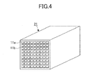
- Each of the plural honeycomb units 21 includes plural through-holes 11a divided by partition walls 11b and arranged in a longitudinal direction thereof (see Fig. 4 ).
- the cross section of the honeycomb unit 21 perpendicular to the longitudinal direction of the honeycomb unit 21 preferably has an area of 10 cm 2 to 200 cm 2 .
- the area of the cross section of the honeycomb unit 21 perpendicular to the longitudinal direction of the honeycomb unit is less than 10 cm 2 , the pressure loss of the honeycomb structural body 20 increases.
- the area of the cross section of the honeycomb unit 21 perpendicular to the longitudinal direction of the honeycomb unit 21 is more than 200 cm 2 , the strength against thermal stress of the honeycomb unit 21 becomes insufficient.
- honeycomb unit 21 is the same as the honeycomb unit 11.
- the thickness of the adhesive layer 22 is preferably 0.5 mm to 2.0 mm. In a case where the thickness of the adhesive layer 22 is less than 0.5 mm, the adhesive strength among the honeycomb units 21 becomes insufficient. On the other hand, in a case where the thickness of the adhesive layer 22 is more than 2.0 mm, the pressure loss of the honeycomb structural body 20 increases.
- honeycomb units 21 having square pillar shapes are formed.
- an adhesive layer paste is applied to the outer peripheral surface of the honeycomb units 21 except for both end faces of the honeycomb units 21.
- the honeycomb units 21 are sequentially adhered together and solidified by drying. Thereby, an aggregate of the honeycomb units 21 can be obtained.
- the adhesive layer paste is not limited in particular.
- the adhesive layer paste may be a mixture of an inorganic binder and inorganic particles, a mixture of the inorganic binder and inorganic fibers, a mixture of the inorganic binder, the inorganic particles, and the inorganic fibers or the like.
- the inorganic binder included in the adhesive layer paste is not limited in particular, the inorganic binder is added as silica sol, alumina sol, or the like. Two or more kinds of inorganic binders may be used. Among the inorganic binders, it is preferable to add silica sol.
- the material constituting the inorganic particles of the adhesive layer paste is not limited in particular, the material may be, for example, a carbide (e.g., silicon carbide), a nitride (e.g., silicon nitride, boron nitride) or the like. Two or more kinds of the inorganic particles may be used. Among the inorganic particles, silicon carbide is preferable because silicon carbide has satisfactory thermal conductivity.
- the inorganic fibers may be silica alumina fibers, mullite fibers, alumina fibers, silica fibers or the like. Two or more kinds of the inorganic fibers may be used. Among the inorganic fibers, alumina fibers are preferable.
- the adhesive layer paste may further include an organic binder.
- the organic binder included in the adhesive layer paste is not limited in particular, the organic binder may be polyvinyl alcohol, methylcellulose, ethylcellulose, carboxymethylcellulose or the like. Two or more kinds of the organic binders may be used.
- the adhesive layer paste may further include, for example, balloons (i.e. minute hollow balls of oxide-based ceramic), a pore-forming agent or the like.
- balloons i.e. minute hollow balls of oxide-based ceramic
- pore-forming agent i.e. minute hollow balls of oxide-based ceramic
- the balloon included in the adhesive layer paste is not limited in particular, the balloon may be an alumina balloon, a glass micro balloon, a shirasu-balloon, a fly ash balloon, a mullite balloon or the like. Two or more kinds of the balloons may be used. Among the balloons, alumina balloons are preferable.
- the pore-forming agent included in the adhesive layer paste is not limited in particular, the pore-forming agent may be spherical acryl particles, graphite or the like. Two or more kinds of the pore-forming agents may be used.
- the cylindrical shaped aggregate of honeycomb units 21 may be obtained by adhering together honeycomb units 21 each of which having a cross-section perpendicular to the longitudinal direction of the honeycomb unit 21 that is molded into a predetermined shape.
- the predetermined shape of the cross-section perpendicular to the longitudinal direction of the honeycomb unit 21 is preferred to be a fan-shape having a central angle of 90°.
- an outer peripheral coating layer paste is applied to the outer peripheral surface of the cylindrical-shaped aggregate of honeycomb units 21 except for both end faces of the honeycomb units 21.
- the outer peripheral coating layer paste may be, for example, the same as or different from the material of the adhesive layer paste.
- the aggregate of the honeycomb units 21 being coated with the outer peripheral coating layer paste is solidified by drying. Thereby, a cylindrical shaped honeycomb structural body 20 is obtained.
- a degreasing process is preferably performed on the honeycomb structural body 20.
- the degreasing conditions can be arbitrarily selected depending on the amount and kind of organic substances. However, the degreasing conditions are preferably at 700 °C for 20 minutes.
- honeycomb structural bodies 10 and 20 may be formed without the outer peripheral coating layer 12.
- honeycomb structural body including a honeycomb unit(s) other than the honeycomb unit 11 or the honeycomb unit 21 may be used.
- the honeycomb unit of the other honeycomb structural body supports zeolite and has plural through-holes divided by partition walls and arranged in a longitudinal direction thereof.
- the material constituting the honeycomb unit supporting zeolite is not limited in particular, the material may be cordierite or the like.
- the zeolite supported on the honeycomb unit 11 is not limited in particular, the zeolite may be ⁇ type zeolite, ZSM-5 type zeolite, a phosphate group zeolite or the like. Two or more of them may be used together.
- the phosphate zeolite is preferable for attaining a satisfactory NOx conversion efficiency.
- the phosphate group zeolite may be a SAPO (silico aluminphosphate) (e.g., SAPO-5, SAPO-11, SAPO-34 or the like), a MeAPO (metal aluminophosphate), a MeAPSO (metallo-aluminosilicophospate) or the like.
- SAPO sico aluminphosphate
- MeAPO metal aluminophosphate
- MeAPSO metal-aluminosilicophospate
- the zeolite it is preferable for the zeolite to include a zeolite ion-exchanged with Cu and/or Fe, and more preferably ion-exchanged with Cu.
- the zeolite ion-exchanged with Cu and/or Fe is preferred to have an ion exchange amount from 1.0 to 5.0 mass%.
- the metal ions used in the ion-exchange of the zeolite are not limited to Cu ions and/or Fe ions. Other transition metal ions enabling improvement of NOx conversion efficiency may be used.
- Fig. 5 illustrates an exhaust gas conversion system 200 which is another example of the exhaust gas conversion system 100 according to an embodiment of the present invention. Except for using an exhaust gas conversion apparatus 210 instead of the exhaust gas conversion apparatuses 120, 130, the configuration of the exhaust gas conversion system 200 is the same as the configuration of the exhaust gas conversion system 100.
- the exhaust gas conversion apparatus 210 can be manufactured by installing (e.g., canning) the exhaust gas conversion apparatus 210 in a metal container (shell) 113 in a state where a holding sealing member 212 is provided at an outer peripheral part of the DPF 121 and the SCR catalyst 131. Thereby, the exhaust gas conversion system 200 can convert the exhaust gas of a diesel engine.
- the exhaust gas conversion system 200 has an ammonia supply part 270 inside the pipe 140 provided between the exhaust gas conversion apparatus 110 and the exhaust gas conversion apparatus 210.
- the ammmonia supply part 270 is, for example, an injection nozzle for injecting ammonia or a compound that generates ammonia by being decomposed.
- the space required for positioning the exhaust gas conversion apparatuses 120, 130 of the conversion system 100 can be reduced.
- an exhaust gas conversion method according to an embodiment of the present invention is a method that is performed by using the above-described embodiment of the exhaust gas conversion apparatus. Therefore, specific details of the exhaust gas conversion method according to the embodiment of the present invention are omitted.
- the honeycomb structural body has a diameter of 228.6 mm and a length of 114.3 mm.
- the honeycomb structural body has a cylindrical shape.
- a raw material paste was prepared by performing the following processes: mixing an ⁇ type silicon carbide (60 parts) having an average particle diameter of 11 ⁇ m and an ⁇ type silicon carbide (40 parts) having an average particle diameter of 0.5 ⁇ m; then, adding carboxyl methylcellulose (5 parts) and water (10 parts) to the mixture of the ⁇ type silicon carbides; then, mixing and kneading the added carboxyl methylcellulose and water with the mixture of the ⁇ type silicon carbides; then, adding a small amount of glycerin and a lubricant UNILUB (Trademark) (manufactured by Nippon Oil & Fats Co.
- the through-holes of one side of the dried honeycomb body were filled with the raw material paste.
- the dried honeycomb body filled with the raw material paste was further dried by the microwave drying apparatus and the hot air drying apparatus. After the drying, the dried honeycomb body was degreased. Then, the degreased honeycomb body was fired at 2200 °C for 3 hours. Thereby, a honeycomb unit is manufactured having a quadrate pillar-shape whose single side is 34.3 mm and length is 203.2 mm.
- the density of the through holes was 46.5 units/cm 2
- the thickness of the partition walls was 0.15 mm
- the average pore diameter of the honeycomb unit was 11 ⁇ m
- the porosity of the honeycomb unit was 42%.
- an adhesive layer paste was prepared by mixing and kneading an alumina fiber (30 parts) having an average fiber diameter of 20 ⁇ m, a silicon carbide (21 parts) having an average particle diameter of 0.6 ⁇ m, silica sol (15 parts) of 30 mass% as solid content, carboxyl methylcellulose (5.6 parts), and water (28.4 parts).
- honeycomb units were adhered together by applying the adhesive layer paste to the outer peripheral surface of the honeycomb units except for the outer peripheral surface of both end parts of the honeycomb units.
- the adhesive layer paste was applied so that the thickness of the adhesive layer is 1.0 mm.
- the adhesive layer paste was solidified by drying at a temperature of 120 °C.
- an aggregate of the honeycomb units was manufactured by cutting the honeycomb units into a cylindrical shape with a diamond cutter so that the cross section perpendicular to the longitudinal direction of the honeycomb units becomes substantially point symmetrical.
- an outer peripheral surface coating layer paste was prepared by mixing and kneading an silica-alumina fiber (23.3 parts) having an average fiber diameter of 50 ⁇ m, a silicon carbide (30.2 parts) having an average particle diameter of 0.3 ⁇ m, silica sol (7 parts) of 30 mass% as solid content, carboxyl methylcellulose (0.5 parts), and water (39 parts).
- the outer peripheral surface coating layer paste was applied to the outer peripheral surface of the aggregate of the honeycomb units except for the outer peripheral surface of both end parts of the aggregate of honeycomb units.
- the outer peripheral surface coating layer paste was solidified by drying the outer peripheral surface coating layer paste at 120 °C. Thereby, a honeycomb structural body having a cylindrical shape with a diameter of 228.6 mm and a height of 203.2 mm was manufactured.
- honeycomb structural body having a single honeycomb unit was used. With this honeycomb structural body, the through-holes on one end of the honeycomb unit of the honeycomb structural body are sealed.
- the honeycomb structural body has a diameter of 228.6 mm and a length of 279.4 mm.
- the honeycomb structural body has a cylindrical shape.
- An outer peripheral coating layer having a thickness of 0.2 mm was formed on the outer peripheral surface of the honeycomb unit except for the outer peripheral surface of both end parts of the honeycomb unit.
- the density of the through holes was 46.5 units/cm 2
- the thickness of the partition walls was 0.30 mm
- the average pore diameter of the honeycomb unit was 15 ⁇ m
- the porosity of the honeycomb unit was 48%.
- the honeycomb unit does not have catalyst supported thereon.
- a raw material paste was prepared by mixing and kneading: SAPO (3100 g) having an average particle diameter of 3 ⁇ m as zeolite; boehmite (895 g); alumina fiber (485 g) having an average fiber diameter of 6 ⁇ m and an average fiber length of 100 ⁇ m; methylcellulose (380 g); oleic acid (280 g); and ion exchanged water (2425 g).
- the above-described outer peripheral coating layer paste was applied to the outer peripheral surface of the fired honeycomb body except for the outer peripheral surface of both end parts of the fired honeycomb body.
- the outer peripheral coating layer paste was applied so that the thickness of the outer peripheral coating layer is 0.2 mm.
- the outer peripheral coating layer paste was solidified by drying at a temperature of 120 °C. Thereby, a honeycomb structural body was manufactured. Further, zeolite (SAPO) of the honeycomb structural body was ion exchanged with copper ions by steeping the honeycomb structural body into a copper nitrate solution. Thereby, the honeycomb structural body 10 was manufactured.
- SAPO zeolite
- the honeycomb structural body 10 has a cylindrical shape with a diameter of 228.6 mm and a length of 203.2 mm.
- the thickness of the partition walls was 0.28 mm and the density of the through holes was 62 units/cm 2 .
- a commercially available cordierite honeycomb structural body was steeped in a dispersion of zeolite (SAPO) being ion exchanged with copper ions of 2.7 mass%. Thereby, zeolite (SAPO) of 70 g/L was supported on the honeycomb structural body.
- the honeycomb structural body includes a single honeycomb unit.
- the honeycomb structural body has a cylindrical shape with a diameter of 228.6 mm and a length of 304.8 mm.
- An outer peripheral coating layer having a thickness of 0.2 mm is formed on the outer peripheral surface of the honeycomb unit except for the outer peripheral surface of both end parts of the honeycomb unit.
- the thickness of the partition walls was 0.28 mm and the density of the through holes was 62 units/cm 2 .
- the DOC-1, the DPF-1, and the SCR catalyst-1 were used as the DOC 111, the DPF 121, and the SCR catalyst 131, respectively.
- the exhaust gas conversion system 200 (see Fig. 5 ) was manufactured by arranging the DOC 111, the DPF 121, and the SCR catalyst 131 in a manner that the distance between the DOC 111 and the DPF 121 is 800 mm and the distance between the DPF 121 and the SCR catalyst 131 is 30 mm.
- an ejection nozzle for ejecting urea water into the pipe 140 was set at a position in which the distance from the DPF 121 is 600 mm.
- the exhaust gas conversion system 100 was manufactured under the same conditions as those of Example 1.
- the exhaust gas conversion system 100 was manufactured under the same conditions as those of Example 1.
- the exhaust gas conversion system 100 was manufactured under the same conditions as those of Example 1.
- the DOC-1, the DPF-1, and the SCR catalyst-1 were used as the DOC 111, the DPF 121, and the SCR catalyst 131, respectively.
- the exhaust gas conversion system 100 (see Fig. 1 ) was manufactured by arranging the DOC 111, the DPF 121, and the SCR catalyst 131 in a manner that the distance between the DOC 111 and the DPF 121 is 800 mm and the distance between the DPF 121 and the SCR catalyst 131 is 200 mm.
- an ejection nozzle for ejecting urea water into the pipe 140 was set at a position in which the distance from the DPF 121 is 600 mm.
- an exhaust gas conversion system was manufactured under the same conditions as those of Example 5.
- the conversion rate of NOx contained in an exhaust gas emitted from an engine having an air volume displacement of 4.2 L was measured by using the exhaust gas conversion systems of Examples 1 to 5 and Comparative Examples 1 and 2.
- NOx conversion rate Nox inflow - Nox outflow / Nox outflow ⁇ 100 %
- the measurement of the NOx conversion rate was performed under the conditions where the engine is in a steady operation state and the exhaust gas has a temperature of 250 °C. Further, urea water was ejected inside the pipe 140 or the pipe 150 from an ejection nozzle so that the mol ratio of ammonia with respect to NOx detected by the NOx sensor of the upstream side of the SCR catalyst 131 becomes 1 when the temperature of the SCR catalyst 131 is equal to or more than 180 °C. Further, the urea water is diffused in the radial direction of the pipe 150 by using a mixer and a swirler.
- the length of the exhaust gas conversion system of Examples 1 to 5 and Comparative Examples 1 and 2 was 1351 mm, 1427 mm, 1452 mm, 1529 mm, 1521 mm, 1521 mm, and 2021 mm, respectively.
- the NOx conversion rate of Examples 1 to 5 and Comparative Examples 1 and 2 was 85%, 83%, 78%, 72%, 80%, 47%, and 83%, respectively.
- length of exhaust gas conversion system indicates the distance from an end part on an upstream side of the DOC 111 to an end part on a downstream side of the SCR catalyst 131 with respect to the direction in which the exhaust gas flows.
- the exhaust gas conversion systems 200 of Examples 1-4 and the exhaust gas conversion system 100 of Example 5 can be formed with a length of 1351 mm to 1529 mm while maintaining a NOx conversion rate of 72% to 85%. Further, the exhaust gas conversion system 200 of Example 1 has a NOx conversion rate that is 5% higher and a length that is 170 mm shorter compared to the exhaust gas conversion system 100 of Example 5 which has the same DOC 111, DPF 121, and SCR catalyst 131 as those of the exhaust gas conversion system 200 of Example 1.
- the exhaust gas conversion system of Comparative Example 2 which has the same DOC 111, DPF 121, and SCR catalyst 131 as those of the exhaust gas conversion system 100 of Example 5, has an NOx conversion rate that is the same (Comparative Example 2 is 83%, Example 5 is 80%) as that of the exhaust gas conversion system 100 of Example 5, the length of the exhaust gas conversion system is increased to 2021 mm.
Landscapes
- Engineering & Computer Science (AREA)
- Chemical & Material Sciences (AREA)
- Chemical Kinetics & Catalysis (AREA)
- Combustion & Propulsion (AREA)
- Mechanical Engineering (AREA)
- General Engineering & Computer Science (AREA)
- Ceramic Engineering (AREA)
- Health & Medical Sciences (AREA)
- Toxicology (AREA)
- Exhaust Gas After Treatment (AREA)
- Exhaust Gas Treatment By Means Of Catalyst (AREA)
- Catalysts (AREA)
Applications Claiming Priority (1)
| Application Number | Priority Date | Filing Date | Title |
|---|---|---|---|
| PCT/JP2011/057854 WO2012131913A1 (ja) | 2011-03-29 | 2011-03-29 | 排ガス浄化システム及び排ガス浄化方法 |
Publications (2)
| Publication Number | Publication Date |
|---|---|
| EP2505802A2 true EP2505802A2 (de) | 2012-10-03 |
| EP2505802A3 EP2505802A3 (de) | 2013-11-20 |
Family
ID=44905594
Family Applications (1)
| Application Number | Title | Priority Date | Filing Date |
|---|---|---|---|
| EP11187074.7A Withdrawn EP2505802A3 (de) | 2011-03-29 | 2011-10-28 | Abgasumwandlungssystem und Abgasumwandlungsverfahren |
Country Status (3)
| Country | Link |
|---|---|
| US (1) | US20120247091A1 (de) |
| EP (1) | EP2505802A3 (de) |
| WO (1) | WO2012131913A1 (de) |
Cited By (1)
| Publication number | Priority date | Publication date | Assignee | Title |
|---|---|---|---|---|
| WO2014068321A1 (en) * | 2012-10-31 | 2014-05-08 | Johnson Matthey Public Limited Company | Catalysed soot filter |
Families Citing this family (2)
| Publication number | Priority date | Publication date | Assignee | Title |
|---|---|---|---|---|
| US9683742B2 (en) * | 2012-08-09 | 2017-06-20 | Bosch Corporation | Pressure sensor integrated glow plug |
| CN118030252A (zh) * | 2021-09-30 | 2024-05-14 | 宁波吉利罗佑发动机零部件有限公司 | 用于发动机排气净化处理的三效催化转化系统及其应用 |
Citations (1)
| Publication number | Priority date | Publication date | Assignee | Title |
|---|---|---|---|---|
| JP2000303826A (ja) | 1999-04-16 | 2000-10-31 | Isuzu Motors Ltd | ディーゼルエンジンの排ガス浄化装置 |
Family Cites Families (11)
| Publication number | Priority date | Publication date | Assignee | Title |
|---|---|---|---|---|
| EP1594594B1 (de) * | 2003-02-12 | 2012-05-23 | Delphi Technologies, Inc. | Vorrichtung zur verminderung von stickoxiden |
| JPWO2005108328A1 (ja) * | 2004-05-06 | 2008-03-21 | イビデン株式会社 | ハニカム構造体及びその製造方法 |
| DE102006043151A1 (de) * | 2005-11-14 | 2007-06-28 | Robert Bosch Gmbh | Verfahren und Vorrichtung zur Regeneration eines Partikelfilters |
| US7874147B2 (en) * | 2007-04-26 | 2011-01-25 | Emcon Technologies Llc | Method and apparatus for a non-catalytic NOx reduction |
| US20090173063A1 (en) * | 2008-01-07 | 2009-07-09 | Boorse R Samuel | Mitigation of Particulates and NOx in Engine Exhaust |
| CN101678348B (zh) * | 2008-05-20 | 2012-07-18 | 揖斐电株式会社 | 蜂窝结构体 |
| JP2010227755A (ja) * | 2009-03-26 | 2010-10-14 | Ngk Insulators Ltd | セラミックハニカム構造体 |
| JP2010242515A (ja) * | 2009-04-01 | 2010-10-28 | Isuzu Motors Ltd | 排気ガス浄化システム及び排気ガス浄化方法 |
| US8635855B2 (en) * | 2009-06-17 | 2014-01-28 | GM Global Technology Operations LLC | Exhaust gas treatment system including a lean NOx trap and two-way catalyst and method of using the same |
| WO2011061841A1 (ja) * | 2009-11-19 | 2011-05-26 | イビデン株式会社 | ハニカム構造体及び排ガス浄化装置 |
| JP2011149402A (ja) * | 2010-01-25 | 2011-08-04 | Isuzu Motors Ltd | 車両の発進補助システム |
-
2011
- 2011-03-29 WO PCT/JP2011/057854 patent/WO2012131913A1/ja not_active Ceased
- 2011-10-28 EP EP11187074.7A patent/EP2505802A3/de not_active Withdrawn
- 2011-11-28 US US13/304,688 patent/US20120247091A1/en not_active Abandoned
Patent Citations (1)
| Publication number | Priority date | Publication date | Assignee | Title |
|---|---|---|---|---|
| JP2000303826A (ja) | 1999-04-16 | 2000-10-31 | Isuzu Motors Ltd | ディーゼルエンジンの排ガス浄化装置 |
Cited By (3)
| Publication number | Priority date | Publication date | Assignee | Title |
|---|---|---|---|---|
| WO2014068321A1 (en) * | 2012-10-31 | 2014-05-08 | Johnson Matthey Public Limited Company | Catalysed soot filter |
| US8940259B2 (en) | 2012-10-31 | 2015-01-27 | Johnson Matthey Public Limited Company | Catalysed soot filter |
| CN104838099A (zh) * | 2012-10-31 | 2015-08-12 | 庄信万丰股份有限公司 | 催化型烟灰过滤器 |
Also Published As
| Publication number | Publication date |
|---|---|
| WO2012131913A1 (ja) | 2012-10-04 |
| US20120247091A1 (en) | 2012-10-04 |
| EP2505802A3 (de) | 2013-11-20 |
Similar Documents
| Publication | Publication Date | Title |
|---|---|---|
| EP2324920B1 (de) | Wabenstrukturkörper und Abgasumwandlungsvorrichtung | |
| US8691157B2 (en) | Honeycomb structure and exhaust gas converter | |
| US8021621B2 (en) | Honeycomb structure, exhaust gas purifying apparatus, and method for producing honeycomb structure | |
| KR100736303B1 (ko) | 벌집형 구조체 | |
| JP5317959B2 (ja) | ハニカム構造体 | |
| EP2130605A2 (de) | Abgasbehandlungsvorrichtung | |
| US8357333B2 (en) | Honeycomb structural body and exhaust gas converting apparatus | |
| EP2319604B1 (de) | Wabenfilter | |
| JP5815220B2 (ja) | ハニカム構造体及び排ガス浄化装置 | |
| EP2810710A1 (de) | Siliko-Alumino-Phosphat | |
| EP2130596A2 (de) | Wabenstruktur | |
| US20090291826A1 (en) | Honeycomb structure | |
| WO2011061839A1 (ja) | ハニカム構造体及び排ガス浄化装置 | |
| EP2505802A2 (de) | Abgasumwandlungssystem und Abgasumwandlungsverfahren | |
| US8609031B2 (en) | Honeycomb structure, exhaust gas conversion apparatus, and manufacturing method of the honeycomb structure | |
| JP2012215166A (ja) | 排ガス浄化システム及び排ガス浄化方法 | |
| US8394347B2 (en) | Exhaust gas conversion system and exhaust gas conversion method | |
| US8685331B2 (en) | Honeycomb structural body and exhaust gas conversion apparatus | |
| JP5563952B2 (ja) | ハニカム構造体及び排ガス浄化装置 | |
| JP2012215167A (ja) | 排ガス浄化システム及び排ガス浄化方法 | |
| EP2338862A1 (de) | Verfahren zur Herstellung von wabenförmig strukturierten Körpern und Verfahren zur Herstellung einer Abgasumwandlungvorrichtung |
Legal Events
| Date | Code | Title | Description |
|---|---|---|---|
| PUAI | Public reference made under article 153(3) epc to a published international application that has entered the european phase |
Free format text: ORIGINAL CODE: 0009012 |
|
| 17P | Request for examination filed |
Effective date: 20111028 |
|
| AK | Designated contracting states |
Kind code of ref document: A2 Designated state(s): AL AT BE BG CH CY CZ DE DK EE ES FI FR GB GR HR HU IE IS IT LI LT LU LV MC MK MT NL NO PL PT RO RS SE SI SK SM TR |
|
| AX | Request for extension of the european patent |
Extension state: BA ME |
|
| PUAL | Search report despatched |
Free format text: ORIGINAL CODE: 0009013 |
|
| AK | Designated contracting states |
Kind code of ref document: A3 Designated state(s): AL AT BE BG CH CY CZ DE DK EE ES FI FR GB GR HR HU IE IS IT LI LT LU LV MC MK MT NL NO PL PT RO RS SE SI SK SM TR |
|
| AX | Request for extension of the european patent |
Extension state: BA ME |
|
| RIC1 | Information provided on ipc code assigned before grant |
Ipc: F01N 3/022 20060101AFI20131017BHEP Ipc: F01N 3/20 20060101ALI20131017BHEP |
|
| 17Q | First examination report despatched |
Effective date: 20160114 |
|
| STAA | Information on the status of an ep patent application or granted ep patent |
Free format text: STATUS: THE APPLICATION IS DEEMED TO BE WITHDRAWN |
|
| 18D | Application deemed to be withdrawn |
Effective date: 20160525 |